
11
Introduction to GPRS and EDGE (2.5G) Supported Mobile Phones
11.1 Introduction
The wireless data services offered by GSM are based on the circuit switched radio transmission. In this instance, at the air interface, a complete traffic channel is allocated for a single user for the entire call duration. Hence with bursty traffic (for example, Internet traffic) this results in highly inefficient resource utilization. It is obvious that for bursty traffic, packet switched bearer services will result in much better utilization of the traffic channels, because a channel will only be allocated whenever it is needed and will be released immediately after the transmission of the packets. Using this principle, multiple users can share one physical channel, for example, one physical channel can be multiplexed among several simultaneous users as required.
In order to address the inefficiencies of circuit switched radio transmission, two cellular packet data technologies have been developed: cellular digital packet data (CDPD) (for AMPS, IS-95, and IS-136) and the general packet radio service (GPRS). Here we will focus only on GPRS. This was originally developed in 1990 for GSM to support data, but later was also integrated within IS-136. We treat GPRS as an evolution from GSM to support packet based services.
Basically GPRS is based on the packet radio principle. Packets can be directly routed from the GPRS mobile (MS) to packet switch networks. Networks based on the Internet protocol (IP) and X.25 networks are supported in the current version of GPRS. Billing can be based on the amount of transmitted data volume, instead of the conventional billing method which is based on the connection time duration.
In short, GPRS improves the utilization of the scarce radio resources, offers volume-based billing, higher data transfer rates, shorter access times, QoS based service, point-to-point in addition to point-to-multi-point services, and simplifies the access to packet data networks.
11.2 System Architecture
In order to integrate GPRS into the existing GSM system architecture, new classes of network nodes, called GPRS support nodes (GSN), have been introduced. GSNs are responsible for the delivery and routing of data packets between the MSs and the external packet data networks (PDN). Figure 11.1, illustrates the system architecture of GPRS.
A serving GPRS support node (SGSN) is responsible for the delivery of data packets from/to the MSs within its service area. The tasks of the SGSN are packet routing and transfer, mobility management (attach/detach and location management), logical link management, and authentication and billing functions, and so on. It manages packet communication sessions between individual mobile stations and the GGSN. The SGSN also interacts with the GSM databases to achieve mobility management functions and obtain subscription information to offer the required services to the mobile station. It is also involved in counting of data packets for billing purpose.
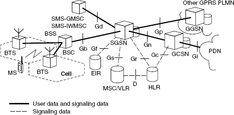
Figure 11.1 GPRS system architecture
A gateway GPRS support node (GGSN) acts as an interface between the GPRS backbone network and the external packet data networks. It converts the GPRS packets coming from the SGSN into the appropriate packet data protocol (PDP) format (for example, IP or X.25) and sends these out on the corresponding packet data network. The GGSN also performs authentication and billing functions. The GGSN is similar to a GMSC (in GSM) as it provides a gateway between the GPRS network and the public PDN (packet data network) or other GPRS networks. It provides authentication and location management functions in addition to firewall functions on the Gi interface to the PDN. All GSNs are connected via an IP-based GPRS backbone network. Within this backbone, the GSNs encapsulate the PDN packets and transmit (tunnel) them using the GPRS tunneling protocol GTP. There are two types of GPRS backbones:
- Intra-PLMN backbone networks connect GSNs of the same PLMN and are therefore private IP-based networks of the GPRS network provider.
- Inter-PLMN backbone networks connect GSNs of different PLMNs. A roaming agreement between two GPRS network providers is necessary to install such a backbone.
In addition, the MSC/VLR may be extended with functions and register entries that allow efficient coordination between packet switched (GPRS) and circuit switched (conventional GSM) services. Examples of this are combined GPRS and non-GPRS location updates and combined attachment procedures. Moreover, paging requests of circuit switched GSM calls can be performed via the SGSN. For this purpose, the Gs interface connects the databases of SGSN and MSC/VLR. To exchange messages in the short message service (SMS) via GPRS, the Gd interface is defined. It interconnects the SMS gateway MSC (SMS-GMSC) with the SGSN.
A packet control unit (PCU) is also added into the BSC to control packet channels and to separate data flow for circuit switched and packet switched calls. The BSC of GSM is also given a new functionality for mobility management and handling GPRS paging. The PCU takes care of the radio resource functionality, such as allocation of the air interface channel blocks. The functional view of a GPRS system is shown in the Figure 11.2.

Figure 11.2 Functional view of GPRS
11.3 Services
Generally, there are two types of services defined for GPRS: the point-to-point (PTP) and the point-to-multi-point (PTM) service. A PTM service is available in later releases. The PTP service offers transfer of user packet data in two modes: connection-less mode (for example, IP) and connection-oriented mode (for example, X.25). On the other hand, the PTM service offers transfer of data packets from one user to multiple users.
GPRS allows defining QoS profiles using the parameters service precedence, reliability, delay, and throughput. The billing of the service is then based on the transmitted (and/or received) data volume, the type of service, and the chosen QoS profile. In a GSM/GPRS network, simultaneous use of conventional circuit switched and packet switched services can be supported based on the classes of MSs as defined below:
Class A: Supports simultaneous operation of GPRS and conventional GSM services.
Class B: Able to register simultaneously with the network for both GPRS and conventional GSM services but can only use one of the two services at a given time.
Class C: MSs can only attach for either GPRS or conventional GSM services. Simultaneous registration and usage is not possible. An exception is SMS messages, which can be sent and received at any time.
11.4 Session Management, Mobility Management, and Routing
In this section, we will see how the data call is set up. The GPRS attach and PDP context activation are required for data call setup. So, before using GPRS services an MS has to register with an SGSN of the GPRS network. When the mobile is first powered ON (in the GPRS default mode), the GPRS attach procedure takes place and this can also occur afterwards depending on the network settings. This is always initiated by MS. Only SGSN is involved in the GPRS attach process and this is transparent to the BSS. In a GPRS attach process the mobile informs the SGSN about its identity IMSI or P-TMSI (packet TMSI, which is allocated by the SGSN on GPRS attach), old routing area identification, mobile class-mark, CKSN, and so on, along with the attach type, which indicates to the SGSN whether this mobile wants to do a GPRS, GSM or both attaches. For MSs using both circuit switched and packet switched services, it is possible to perform a combined GPRS/IMSI attach procedure. The SGSN will attach the mobile and inform the HLR if there is a change in the routing area. If the attach type is both, then the SGSN will also do a location update with the VLR. The disconnection from the GPRS network is known as GPRS detach, which can be initiated either by the MS or the network (SGSN or HLR).
Before the MS can transmit or receive any information, it needs to activate a packet data protocol (PDP) context. A mobile can establish multiple PDP context sessions for different applications. A PDP context activates a packet communication session with the SGSN (Figure 11.3). It provides information for mapping and routing information between the MS and the GGSN. The SGSN asks the GGSN for a PDP context. Then the GGSN will create a new entry in its PDP context table and send confirmation to the SGSN, including the address, if it is dynamic. The mobile in a PDP context activation procedure either specifies a static IP address or requests an IP address. It also specifies the access point with which it wants to communicate, such as some intranet network or an Internet service provider (ISP). It also aks for the desired QoS and a network service access point identifier (NSAPI), which is used to discriminate data packets of different applications. When the SGSN obtains the mobile information, it decides on the GGSN connected to the APN and forwards the request to the GGSN. Then, if a static address exists, the GGSN connects the MS to the desired access point; unless it gets an IP address from the APN. The GGSN also provides some transaction identifiers for communication of data to reference this mobile between the GGSN and SGSN. The SGSN in its request also provides a negotiated QoS based on the subscription information of the user and availability of services. Once the communication and activation at GGSN is successful, the appropriate information is forwarded to the mobile.

Figure 11.3 GPRS attach and PDP context activation process
As GPRS uses packet-based architecture, where a connection is granted during traffic and released after completion, location update is thus essential here. However, in order to avoid too much consumption of the resources and power for frequent updates during idle time and extra delay for regular paging for each downlink packet, a state model has been defined for location management of GPRS, as shown in Figure 11.4. A mobile can be in any of three states (idle, standby, and ready) based on its need and the location update frequency depends on the MS state.
- Idle State: The mobile is powered on in the idle state, but not attached to the GPRS. In this state the mobile is not reachable, and no location updating is performed, that is, the current location of the MS is unknown to the network.
- Ready State: Upon performing a GPRS attach, the mobile enters into the ready state. Here the mobile is currently engaged in packet transfer or has recently terminated a packet transfer. With a GPRS detach the mobile may disconnect from the network and return to the idle state again and all PDP contexts will be deleted. An MS in the ready state informs its SGSN with respect to its every movement to a new cell.
- Standby State: The mobile is powered on and attached to the GPRS but no packet transfer is in progress. The standby state is reached when a mobile does not send any packets for a long period of time. This causes the ready timer to expire. In this state routing area updates are sent as needed. In the standby state, a GSM location area (LA) is divided into several routing areas (RA). In general, an RA consists of several cells. The SGSN will only be informed when an MS moves to a new RA. To find out the current cell of an MS in the standby state, paging of the MS within a certain RA must be performed.

Figure 11.4 State model of a GPRS mobile station
In general, GPRS mobility management consists of two levels:
- Micro-mobility management performed by SGSN tracks the current routing area or cell of the mobile station.
- Macro-mobility management keeps track of the mobile station's current SGSN and stores it in the HLR, VLR, and GGSN.
The routing area consists of several cells, and one location area includes several routing areas, as shown in the Figure 11.5.

Figure 11.5 Location area and routing area
11.5 GPRS Protocol Architecture
The protocol layer is split into two planes. On one side there is the transmission plane, which is mainly used for the transfer of user data. The signaling plane, on the other side, is used for the control and support of the transmission plane functions.
11.5.1 Transmission Plane
Figure 11.6 depicts the GPRS network protocol architecture for the transmission plane. This provides transmission of user data and its associated signaling, such as for flow control, error detection, and error correction.

Figure 11.6 Protocol architecture of the GPRS transmission plane
11.5.1.1 Air Interface
The air interface is located between the BSS and MS, and it uses the following protocols.
- Radio Link Control (RLC): The main purpose of the RLC layer is to establish a reliable link between the MS and the BSS. This includes the segmentation and reassembly of LLC frames into RLC data blocks and ARQ of uncorrectable code words.
- Medium Access Control (MAC): The main functions of the MAC layer include controlling the access signaling procedures to the GPRS radio channel and the multiplexing of signaling and RLC blocks from different users onto the GSM physical channel. The MAC layer controls the access attempts of an MS on the radio channel shared by several MSs. It employs algorithms for contention resolution, multi-user multiplexing on a PDTCH, and scheduling and prioritizing based on the negotiated QoS. The GPRS MAC protocol is based on the principle of slotted Aloha. In the RLC/MAC layer, both the acknowledged and unacknowledged modes of operation are supported.
- Physical and RF Layer (PLL, RFL): This layer can be split into two sub-layers: the radio frequency layer (RFL), which handles the radio and baseband part (physical channel management, modulation, demodulation, and transmission and reception of radio blocks), and the physical link layer (PLL), which manages control of the RFL (power control, synchronization, measurements, and channel coding/decoding).
A relay function is implemented in the BSS to relay the LLC PDUs between the air interface and the Gb interface.
11.5.1.2 Gb Interface
The interface between BSS and SGSN is the Gb interface. This supports data transfer in the transmission plane along with the following protocols.
- BSS GPRS Protocol (BSSGP): This is data link control on the radio link level. The BSS GPRS application protocol (BSSGP) delivers routing and QoS-related information between the BSS and SGSN.
- Network Service (NS): This transports BSSGP PDUs and is based on a frame relay connection between the BSS and SGSN.
A relay function is implemented in the SGSN to relay the packet data protocol (PDP) PDUs between the Gb and Gn interfaces.
11.5.1.3 Gn/Gp Interface
The Gn interface is defined between two GSNs (SGSN or GGSN) within the same PLMN, while the Gp interface is between two GSNs belong to different PLMNs. The Gn/Gp interface is used to transfer packets between the SGSN and the GGSN in the transmission plane. The following protocols are supported in Gn/Gp interface.
- GPRS Tunneling Protocol (GTP): This is a data link control protocol on a logical link level. The GPRS tunneling protocol (GTP) tunnels the user data packets and related signaling information between the GSNs. GTP packets carry the user's IP or X.25 packets. In the GPRS backbone, we have an IP/X.25-over-GTP-over-UDP/TCP-over-IP transport architecture.
- User Datagram Protocol (UDP): This carries GTP packet data units (PDUs) in the GPRS core network for protocols that do not require a reliable data link.
- Internet Protocol (IP): IP is employed in the network layer to route packets through the backbone.
11.5.1.4 Interface between MS and SGSN
This interface between MS and SGSN supports the following protocols.
- Subnet Work-dependent Convergence Protocol (SNDCP): This is used to transfer data packets between SGSN and MS. This protocol maps the IP protocol to the underlying network. SNDCP also provides other functions such as compression, segmentation, and multiplexing of network layer messages.
- Logical Link Control (LLC): The logical link control (LLC) layer provides a highly reliable logical link between an MS and its assigned SGSN. Its functionality is based on the well known HDLC protocol that includes sequence control, in-order delivery, flow control, detection of transmission errors, and retransmission (automatic repeat request (ARQ). LLC frames are variable in size (with temporary ID) maximum 1600 bytes.
11.5.2 Signaling Plane
The signaling plane consists of protocols for control and support of the transmission plane functions. The signaling plane architecture between the MS and the SGSN is shown in Figure 11.7.

Figure 11.7 Signaling plane between MS-SGSN
11.5.2.1 Interfaces between MS and SGSN
The signaling plane is made up of the following protocols.
- GPRS Mobility Management (GMM): This supports mobility management functionalities such as GPRS attach/detach, security functions, RA update, PDP context activation, and location update.
- Session Management (SM): This supports functionalities such as PDP context activation, PDP context modification, and PDP context deactivation and so on.
The signaling architecture between SGSN and the registers HLR, VLR, and EIR uses the same protocols as conventional GSM and extends them with GPRS-specific functionality. An enhanced mobile application part (MAP) is employed between SGSN and HLR as well as between SGSN and EIR. The MAP is a mobile network specific extension of the signaling system SS7. It transports the signaling information related to location updates, routing information, user profiles, and handovers. The exchange of MAP messages is accomplished over the transaction capabilities application part (TCAP) and the signaling connection control part (SCCP). The base station system application part (BSSAP+) includes functions of the GSM's BSSAP. It is applied to transfer signaling information between the SGSN and the VLR (Gs interface). This includes signaling of the mobility management, when coordination of GPRS and conventional GSM functions is necessary (for example, combined GPRS and non-GPRS location update, combined GPRS/IMSI attach, or paging of an MS via GPRS for an incoming GSM call).
The overall protocol software architecture inside the mobile handset of a GSM protocol stack is modified to support GPRS, which is shown in Figure 11.8.
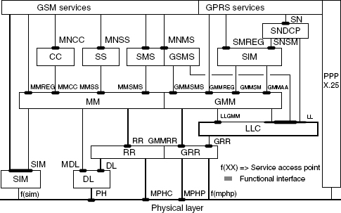
Figure 11.8 Protocol stack architecture of GPRS/GSM mobile
As discussed above, GPRS defines additional layers to adapt packets from application and for optimum resource utilization and these are SNDCP, SM, GMM, LLC, and RLC/MAC. GMM is responsible for registration, authentication, location management, and attach. SM is responsible for setting up data call, and negotiates QoS (XID parameters). RLC is responsible for packet segmentation/reassembly, flow control error correction, and so on, whereas MAC is responsible for ARFCN, TLLI, frame number, USF, TFI, RRBP, block number, radio priority, and so on.
11.6 Air Interface–Physical Layer
As discussed earlier, on the physical layer, GSM uses a combination of FDMA and TDMA for multiple access. Each of the 200 kHz frequency channels is divided into eight TDMA channels by dividing each of them into eight time slots. The eight time slots in these TDMA channels form one TDMA frame. The recurrence of one particular time slot defines a physical channel. The channel allocation in GPRS is different from the original GSM. GPRS allows a single MS to transmit or receive on multiple time slots on the same TDMA frame (multi-slot operation). It results in a very flexible channel allocation: ideally one to eight time slots per TDMA frame can be allocated for one MS (Figure 11.9). So, theoretically a maximum data rate of 11.2 × 8 kbps rates can be achieved. Moreover, uplink and downlink channels are allocated separately, which efficiently supports asymmetric data traffic. A multi-frame structure for GPRS packet data channel consists of 52 TDMA frames, whereas a GSM traffic channel uses a 26-frame structure.
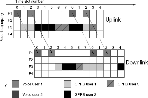
Figure 11.9 Slot allocation for users
11.6.1 Physical Channels
In GPRS the channels are allocated only when the data packets need to be sent or received, and channels are released after the transmission. With respect to the usage of scarce radio resources, this is more efficient for bursty traffic. According to this principle, multiple users can share one physical channel. A cell supporting GPRS may allocate physical channels for GPRS traffic and such a physical channel is denoted as the packet data channel (PDCH). The radio resources of a cell are shared by all GPRS and non-GPRS MSs located in this cell. The PDCHs are taken from the common pool of all channels available in the cell. The mapping of physical channels to either packet switched (GPRS) or circuit switched (conventional GSM) services can be performed dynamically (capacity on demand principle), depending on the current traffic load, the priority of the service, and the multi-slot class. PDCHs are dynamically allocated in the cell by the network. The PDCH is mapped on a 52-multi-frame structure as shown in Figure 11.10. The 52-multi-frame consists of 12 radio blocks (B0 to B11) of four consecutive TDMA frames and four idle frames (frames 12, 25, 38, and 51), leading to a total of 52 (=3 × 4 + 1 + 3 × 4 +1 + 3 × 4 + 1 + 3 × 4 + 1) frames. One block essentially consists of four slots (bursts).
Figure 11.10 One multi-frame for PDCH
11.6.2 Logical Channels
As with GSM, GPRS uses the concept of logical channels mapped on top of the physical channels (Figure 11.11). Two types of logical channels have been defined, namely traffic channels and control channels. Three subtypes of control channels have been defined for GPRS: broadcast, common control, and associated.

Figure 11.11 Channel structure in GPRS
Table 11.1 lists the packet data logical channels defined for GPRS.
Table 11.1 Logical channels in GPRS

In 52-multi-frame structure, there are four idle frames, out of which two TDMA frames are reserved for transmission of the PTCCH, and the remaining two frames are idle frames. The mapping of the logical channels onto the blocks B0–B11 of the multi-frame can vary from block to block and is controlled by parameters that are broadcast on the PBCCH.
Besides the 52-multi-frame, which can be used by all logical GPRS channels, a 51-multi-frame structure is also defined. It is used for PDCHs carrying only the logical channels PCCCH and PBCCH.
The packet data traffic channel (PDTCH) is employed for the transfer of user data. It is assigned to one mobile station (or in the case of PTM, to multiple mobile stations). One mobile station can use several PDTCHs simultaneously.
PBCCH is used by the BSS to broadcast specific information about the organization of the GPRS radio network to all GPRS MSs of a cell. It also broadcasts important system information about circuit switched services, so that a GSM/GPRS MS does not have to listen to the broadcast control channel (BCCH). The presence of PBCCH in the cell is optional. When there is no PBCCH in the cell, the information needed by the mobile to access the network for a packet transfer is broadcast on BCCH.
PCCCH is a bi-directional point-to-multipoint signaling channel that transports signaling information for network access management, for example, for allocation of radio resources and paging. It consists of four subchannels:
- PRACH is used by an MS to request one or more PDTCH.
- PAGCH is used to allocate one or more PDTCH to an MS.
- PPCH is used by the BSS to find out the location of an MS (paging) prior to downlink packet transmission.
- PNCH is used to inform an MS about incoming PTM messages (multicast or group call).
Packet dedicated control channel is a bi-directional PTP signaling channel. It consists of two subchannels:
- PACCH is always allocated in combination with one or more PDTCH that are assigned to one MS. It transports signaling information related to one specific MS (for example, power control information).
- PTCCH is used for adaptive frame synchronization.
11.6.3 Channel Allocation
Figure 11.12 shows the principle of the uplink channel allocation (mobile originated packet transfer). An MS requests radio resources for uplink transfer by sending a “packet channel request” on the PRACH or RACH and the network answers on PAGCH or AGCH, respectively. It tells the MS which PDCHs it can use. A so-called uplink state flag (USF) is transmitted in the downlink to tell the MS which are the time slots that the MS should use to transmit on uplink, based on whether the uplink channel is free or not.

Figure 11.12 Uplink and downlink channel allocation (mobile originated packet transfer and mobile terminated packet transfer)
11.6.3.1 Reservation and Release of Radio Resources
A temporary block flow (TBF) is a physical connection between two radio resource (RR) entities (L3) to support the unidirectional transfer of LLC frames using PDCHs. The TBF is an allocated radio resource on one or more PDCHs and contains a number of RLC/MAC blocks carrying one or more LLC frames. A TBF is temporary and is maintained only for the duration of the data transfer, which means until there are no more blocks to be transmitted and all the transmitted blocks have been acknowledged by the receiving RR entity. Concurrent TBFs may be established in opposite directions (Figure 11.13). Once the data transfer is finished, the TBF is released.

Figure 11.13 TBF establishment for 1 phase and 2 phase access
When the mobile sends continuous data to the network, it requests the establishment of an uplink TBF by sending signaling information over CCCH or PCCCH. When the network wants to send data to the mobile, it assigns a downlink TBF between the two RR entities. The number of TBFs per mobile and per direction is limited to one. However, TBFs belonging to different mobiles can share the same PDCH.
In a resource assignment message, which comes from the network to the MS, each TBF is assigned a unique temporary flow identity (TFI) by the network. The TFI is unique in both directions. It allows for the multiplexing of several users over the same time slot, and it can provide the assignment of priority classes. In the RLC/MAC layer, TFI is used instead of the MS identity, and it is included in every RLC header, which belongs to the corresponding TBF. Allocation of radio resources can happen in one or two phases. In one-phase access, the network may not know exactly, which MS owns the allocation until the first block from the MS is received by the network. In two-phase access, the MS which requested resource allocation is automatically uniquely defined. Both the network and the MS can require the two-phase access.
In principle, three different medium access modes are supported. These are called fixed allocation, dynamic allocation, and extended dynamic allocation. According to 3GPP Release 1997, the support for extended dynamic allocation is optional.
Dynamic Allocation
Dynamic allocation allows unused channels to be allocated as packet data channels (PDCHs) and if a higher priority application requires resources the PDCHs can be released. The mobile station monitors the downlink to determine when to send data on the uplink. The uplink state flag (USF) is assigned to the mobile station during the establishment of a TBF. The USF is included in the header of each RLC/MAC data block sent on the downlink. It designates which mobile is allowed to transmit data in that particular PDCH of the next uplink radio block. When the mobile station detects its assigned USF it can transmit either a single RLC/MAC block or a set of four RLC/MAC blocks. Because all the mobile stations constantly monitor the USF, the allocation scheme can be altered dynamically.
In principle, dynamic allocation allows uplink transmission to mobiles sharing the same PDCH, on a block-by-block basis. During the uplink TBF establishment, an uplink state flag (USF) is given to the MS for each allocated uplink PDCH. The USF is used as a token given by the network to allow transmission of one uplink block.
Whenever the network wants to allocate one radio block occurrence on one uplink PDCH, it includes, on the associated downlink PDCH, the USF in the radio block immediately preceding the allocated block occurrence. When the mobile decodes its assigned USF value in a radio block sent on a downlink PDCH associated with an allocated uplink one, it transmits an uplink radio block in the next uplink radio block occurrence, which means at the B(n) radio block, if the USF was detected in the B(n − 1) radio block. The USF coding (3 bits) enables eight mobiles to be multiplexed on the same uplink PDCH. Dynamic allocation implies the constant monitoring (radio block decoding) of the downlink PDCHs associated with the allocated uplink PDCHs. The USF allows the sending of one block in the next uplink occurrence. However, dynamic allocation can also be used in such a way that the decoding of one USF value allows the mobile to send four consecutive uplink blocks on the same PDCH. The choice between one block or four blocks is indicated during the TBF establishment by the network to the mobile.
Extended Dynamic Allocation
The extended dynamic allocation scheme offers an improvement over the dynamic allocation scheme. Some RR configurations are not compliant with all MS multi-slot classes in the dynamic allocation scheme. In the dynamic allocation scheme, the MS must decode all USF values on all downlink PDCHs associated with the allocated uplink PDCHs.
Extended dynamic allocation allows the mobile station to be allocated multiple time slots in a radio block without having to monitor the USF value for each time slot. It differs from dynamic allocation in that when a mobile station sees its USF value in a particular downlink time slot, it assumes that it can use that time slot and all higher numbered time slots in the allocated set during the next uplink radio block.
The mobile monitors its assigned PDCHs starting from the lowest numbered one (the one that is mapped on the first allocated time slot in the TDMA frame), then it monitors the next lowest numbered time slot, and so on. Whenever the MS detects its assigned USF value on a PDCH, it transmits one radio block or a sequence of four radio blocks on the same PDCH and all higher-numbered assigned PDCHs. The mobile does not need to monitor the USF on these higher PDCHs. This is of particular interest in some RR configurations that are not compliant with all MS multi-slot classes in the dynamic allocation scheme.
Let us take the example of a class 12 MS, which is defined by: a maximum number of four receive time slots per TDMA frame and a maximum number of four transmit time slots per TDMA frame, but the total number of transmit and receive time slots per TDMA frame less than or equal to 5.
The network cannot allocate four uplink PDCHs to a MS multi-slot class-12 with the dynamic allocation. Indeed, the MS must decode the USF fields on the four associated downlink PDCHs. This means that the MS would have to receive on four time slots to be able to transmit on four time slots. This gives a total number of eight receive and transmit time slots, which is not compliant with a multi-slot class-12 MS. In the case of extended dynamic allocation, the network can allocate four uplink PDCHs without exceeding a total number of five receive and transmit time slots.
Fixed Allocation
Fixed allocation assigns the mobile station exclusive use of certain channels. The network commands the mobile station to use fixed allocation via the packet uplink assignment message. This message also contains a bitmap indicating the specific PDCHs, which may be used to transfer data. The network allocates uplink radio blocks using bitmaps (a series of zeros and ones). A 0 indicates that the mobile is not allowed to transmit, and a 1 indicates a transmission occurrence. The bitmaps are sent during the establishment of the uplink TBF. If more uplink resources are required during the uplink TBF, the network sends a bitmap in the downlink on the PACCH.
Fixed allocation enables a given MS to be signaled with the predetermined uplink block occurrences on which it is allowed to transmit. The network assigns to each mobile a fixed uplink resource allocation of radio blocks onto one or several PDCHs.
A fixed allocation TBF operates as an open-ended TBF when an arbitrary number of octets are transferred during the uplink TBF. When the allocated bitmap ends, the MS requests a new bitmap if it wishes to continue the TBF.
A fixed allocation TBF operates as a close-ended TBF when the MS specifies the number of octets to be transferred during the uplink TBF establishment.
11.7 Packet Data Transport Across Layers
In Figure 11.14, the PDU flow over the GPRS transmission plane is shown.
A radio block consists of one byte MAC header, followed by RLC data or an RLC/MAC control block and is terminated by a 16-bit block check sequence (BCS). It is carried by four normal bursts (that is, 114 bits long). GPRS allows a maximum of eight slots per frame to be allocated to the PDTCH on the downlink and uplink on all radio blocks B0-B11. On the downlink, an IP datagram of 1500 bytes to be transmitted as an LLC PDU must first be fragmented into 29 RLC blocks. These blocks can be transmitted using a total of 116 consecutive bursts.
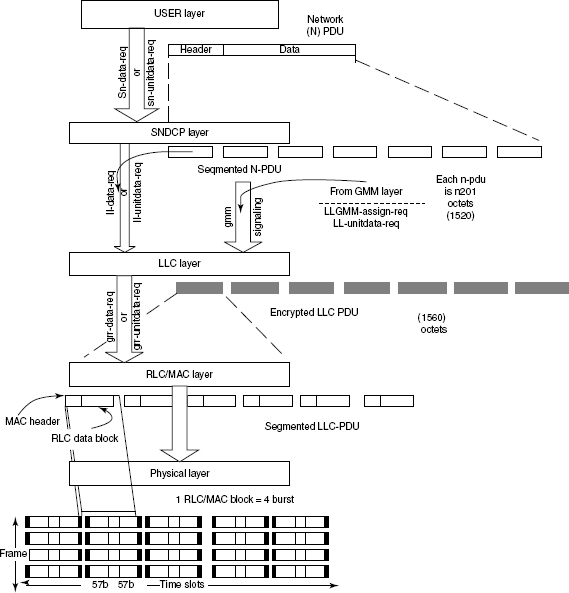
Figure 11.14 Illustrates the PDU flow through transmission plane of the GPRS protocol stack
Each radio block is 20 ms and contains 4 bursts, spread over 4 TDMA frames; 12 radio blocks on a 52-multi-frame is spread over 240 ms. The number of radio blocks is 50 per secondand the frame length is 4.6 ms.
As shown in Figures 11.15 and 11.16, the bursts are formed from the LLC data packet information after several processings, and finally they are mapped to normal burst of the PDTCH. As shown in the Figure 11.17, the block data of four frames each with 114 bits (57 + 57) of information is mapped into four successive PDCH. So, in the physical layer, on every 20 ms time interval (TTI) 456 bits are available after encoding and puncturing. These data are then put in four bursts each contains 57 + 57 bits of data.
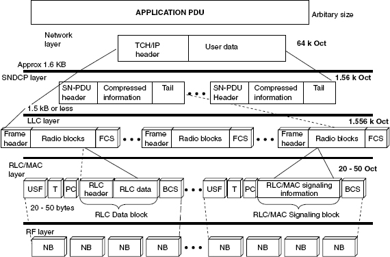
Figure 11.15 Segmentation and encapsulation of GPRS data packets. PH, packet header; FH, frame header; FCS, frame check sequence; and BCS, block check sequence
11.8 Channel Coding and Puncturing
The channel coding technique in GPRS is fairly similar to the one employed in conventional GSM. An outer block coding, an inner convolution coding, and an interleaving scheme are used here. Four different coding schemes are defined as shown in Table 11.2.
Based on the quality of the channel, one of these four coding schemes is chosen for the coding of the traffic channel (PDTCH). CS-1 offers the lowest rate but has the highest robustness. Thus, under very bad channel conditions, we may use CS-1 and obtain a data rate of 9.05 kbps per GSM time slot. However, under good channel conditions, we transmit without convolutional coding using the CS-4 scheme (no protection) and achieve a data rate of 21.4 kbps per time slot. The CS-1 scheme is used for coding of the signaling channels. Using all eight time slots, we may obtain a maximum data rate of 171.2 kbps. In practice, multiple users share the time slots, hence a much lower bit rate is available to the individual user.
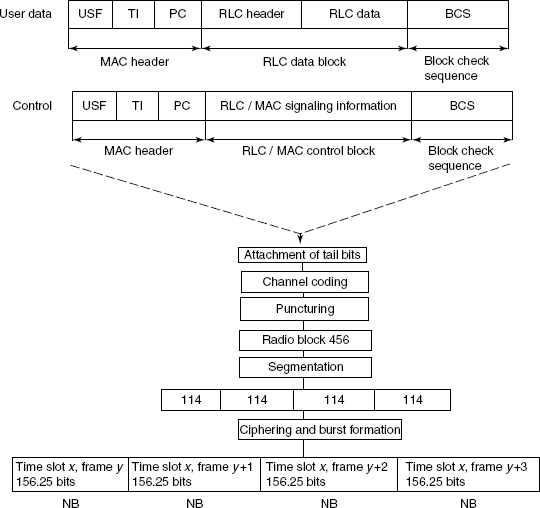
Figure 11.16 Data processing in GPRS
Table 11.2 Channel coding schemes for logical traffic channels in GPRS


Figure 11.17 Packet data channel logical frame
The bit processing for any coding scheme is shown in Figure 11.18. With the payload, a block check sequence (BCS) is added, and thereafter the USF, either in its original form or with extra redundancy, is prefixed (pre-coded USF). Tail bits are then added and the resultant bit stream is convolutionally coded. Next, the output bits are punctured to give 456 bits (Figure 11.19). CS-1: 181-bits payload, along with the 3-bits USF, 40-bits USF and 4-bit tail bits are convolutionally coded to provide 456 bits. CS-2: 268-bits payload, 6-bits pre-coded USF, 16-bits BCS, 4-bit tail bits add up to 294, after a ½ convolution provides a 588-bits stream, which is punctured to give 456 bits. CS-3: 312-bits payload, 6-bits pre-coded USF, 16-bits BCS, 4-bit tail bits adds up to 338 after a ½ convolution provides a 676-bits stream, which is punctured to give 456 bits. CS-4: 428-bits payload, 12-bits precoded USF, 16-bits BCS adds up to 456 bits. Using CS-4, the three USF bits are mapped to 12 bits. No convolutional coding is applied.
Figure 11.18 GPRS data packet processing flow
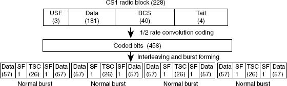
Figure 11.19 Channel coding in CS1
For the convolution coding, a non-systematic rate ½ encoder with constraint length 4 is used. It is defined by the generator polynomials:
![]()
In order to intimate to the receiver about which coding scheme is used by the transmitter, the stealing flags are used. Four different coding schemes can be identified by 2 stealing flags in a burst, but a total of 8 stealing flags are used instead: CS-1 – 11111111, CS-2 – 11001000, CS-3 – 00100001, and CS-4 uses stealing flags 00010110.
11.8.1 Puncturing
The puncturing scheme used in GPRS is shown in Figure 11.20.

Figure 11.20 Puncturing schemes in GPRS
In Figure 11.21, the data bit processing for the CS-4 coding scheme is shown. The FBI (final bit indicator) is inside the RLC header for final block poll setting.

Figure 11.21 Information bit processing for CS4 coding scheme (1 symbol = 1 bit − GSMK)
After encoding, the code words are input into a block interleaver of depth 4. On the receiver side, the code words are de-interleaved. The decoding is performed by using the Viterbi algorithm.
11.9 Cell Re-selection
As in the GSM, in GPRS the mobile performs cell re-selection, but there are some differences compared with GSM. In GPRS the mobile performs cell re-selection when it is in idle mode as well as in packet transfer mode. The cell re-selection is either performed by the mobile autonomously or is optionally controlled by the network. As such, there is no handover in GPRS, just the cell re-selection. So, when there is a re-selection during a packet transfer, data transfer is interrupted and it has to be started again in the new cell. There is an interruption of the packet transfer during the re-selection phase. Although the GPRS cell re-selection algorithms used by the mobile are based on the same principles as those used in GSM, they have been slightly modified in order to provide more flexibility.
11.9.1 Routing Area Update Procedure
The MS sends an RA update request containing the cell identity and the identity of the previous routing area to the new SGSN. Then the new SGSN asks for the context (GGSN address and tunneling information) of the MS from the old SGSN. The new SGSN informs the GGSNs of the new SGSN address and tunneling information. It also informs the HLR, which cancels the MS information context in the old SGSN. The HLR loads the subscriber data to the new SGSN, which acknowledges this to the MS. The previous SGSN is requested to transmit the undelivered data to the new SGSN.
11.10 Radio Environment Monitoring
In GPRS the radio environment monitoring is essential, as it is in GSM. The MS performs different types of radio measurements and the results are reported to the network and this is used by the RLC. These estimations are also used by the mobile itself to compute its transmission power (open-loop power control), for cell selection and cell re-selection purpose.
The mobile performs the following types of measurements.
- Received Signal Level (RXLEV) Measurements: For the purpose of cell re-selection, the RXLEV measurements are performed on both the serving cell and neighboring cells. The serving cell RXLEV measurements can also be used for downlink coding scheme adaptation, network-controlled cell re-selection, and power control during the packet-transfer mode.
- Quality (RXQUAL) Measurements: During the packet-transfer mode the mobile estimates the quality of the received downlink blocks. The RXQUAL is computed from the average BER before channel decoding. The RXQUAL can be used by the network for network-controlled cell re-selection, dynamic coding scheme adaptation, and downlink power control. In the packet idle mode, no quality measurements are performed.
- Interference Measurements: Interference measurements have been introduced for GPRS. These correspond to a received signal level measurement performed on a frequency that is different to a beacon frequency. The interest is in having an estimation of the interference level on the PDTCH. It can be used by the network to optimize the mobile RR allocation, to select a more appropriate coding scheme, to trigger a network-controlled cell re-selection, and for power control or for network statistics.
The RXLEV and RXQUAL measurements are also performed on the BSS side. These are used for network-controlled cell re-selection, uplink power control (closed loop), and dynamic coding scheme adaptation.
11.10.1 Principles of Power Control
In a wireless environment, the power control is very important in order to reduce the co-channel interference and to improve the spectrum efficiency, while maintaining an optimum radio link quality and to reduce the power consumption in the MS. Power control can be performed in both uplink and downlink directions. In GPRS, as the channels are not necessarily a continuous two-way connection, studying the channel is very difficult. Because of this, power control in GPRS is more complicated than for a circuit-switched connection.
11.11 Multi-Slot Class
In order to provide higher throughputs, a GPRS MS may transmit or receive using several time slots in a TDMA frame, for example, it can use one or more slots (multi-slot) of the same TDMA frame. The multi-slot capability of the GPRS MS is indicated by the multi-slot class (MSC). The implementation complexity of an MS varies, based on the number of support transmission and reception slots in a TDMA frame. To have a reasonable impact on the MS design complexity, it has been decided to allow the RF transmission on several slots of a TDMA frame, with a number of restrictions, as listed below.
- Although several bursts can be transmitted within a TDMA frame, all should be on the same carrier frequency (ARFCN).
- The MS needs to perform the adjacent cell measurements, or monitoring, in between the transmission and reception. Based on the mobile capability, delay constraints are needed between the transmission and reception of bursts.
- If m time slots are allocated to an MS for reception and n time slots are allocated for transmission, then the system requires a minimum of (m, n) reception–transmission time slots that have the same time slot number (TN) within the TDMA frame.
Two types of MSs are defined.
- Type-1 Mobiles: This type of mobiles are not capable of transmitting and of receiving at the same time, for example, at a given instant of time it either transmits or receives.
- Type-2 Mobiles: This type of mobiles are capable of transmitting and receiving at the same time. Thus they are more complex in design, and the transmitter and receiver circuits are completely separate and expensive.
For these two types of mobile, there are various multi-slot classes, based on the capability of the MS in terms of complexity. Depending on the multi-slot class number, the mobile is able to transmit on a maximum of Tx time slots, and to receive on a maximum of Rx time slots within a TDMA frame, but the sum of (Tx + Rx) slots is limited. The maximum number of Tx slots and the maximum Rx slots are not active at the same time (see Tables 11.3 and 11.4).
Based on the following time constraints, the different types of type-1 multi-slot classes can be defined.
- Tta – is used to set the minimum allowed delay between the end of a transmit or receive time slot and the next transmit time slot, with an adjacent cell received signal measurement to be performed in between. This is the maximum number of time slots allowed to the MS to measure an adjacent cell received signal and to get ready for transmission.
- Trb – is the minimum delay between the end of a transmit or receive time slot and the first next receive time slot.
- Tra – is the minimum number of allowed time slots between the end of a transmit or receive time slot and the next receive time slot, in between an adjacent cell measurement.
- Ttb – is the minimum number of time slots between the end of a receive or transmit time slot and the first next transmit time slot, without adjacent cell measurement in between.

Table 11.4 Type-2 MS

11.12 Dual Transfer Mode (DTM)
Dual transfer mode (DTM) is a 3GPP baseline R99 feature. It is a protocol based on the GSM standard that allows simultaneous transfer of circuit switched (CS) voice and packet switched (PS) data over the same radio channel (ARFCN). A DTM capable mobile phone can be simultaneously engaged in both CS and PS calls for voice and packet data connection in GSM/EDGE networks. A simultaneous voice and data call implies that a data call might start during an ongoing voice call or a voice call might start during an ongoing data call. If a PS call begins first, and next a CS call needs to be started, then the TBF (data call) is released. A dedicated connection for the voice call is initiated and finally, the mobile phone uses DTM for re-establishing the data connection. One common class implemented by the mobile phone vendors is the DTM Multi-slot Class 11. For example, the technical specification of a Nokia N95 states a speed of DL/UL of 177.6/118.4 kbps.
11.13 EDGE (Enhanced Data Rates for GSM Evolution) Overview
In the previous section, we noted that to support higher data rates, GPRS employs variable-rate coding schemes and multi-slot operation. The use of packet access further enhances system throughput and spectrum efficiency. However, the peak date rate for GPRS is limited to about 115 kbps, which is not sufficient for supporting popular Internet applications such as web browsing, e-mail, video services, surveillance, voice over Internet, and so on. So, even higher rates are desirable. Therefore, ETSI has developed EDGE (enhanced data rates for GSM evolution) technologies to improve the existing 2G network capacity. EDGE is generally classified as 2.75G, although it is part of ITU's 3G definition. EDGE was introduced into GSM networks in 2003, initially by the operator network Cingular in the USA.
This technology is compatible with TDMA and GSM networks. The EDGE system employs a dynamic adaptation between a number of modulation and coding schemes, as a means of providing several hundred kbps peak data rates in a macro-cellular environment, while supporting adequate robustness for impaired channels. The Hybrid ARQ (Type II) is considered to improve the performance. When it is combined with the GPRS, it allows a data flow of 384 kbps (limited to 200 kbps for the EDGE Compact) and a theoretical maximum flow of 474 kbps. The evolution of GPRS towards EDGE is known as E-GPRS (enhanced GPRS). It is also known as EDGE classic.
A major impact for supporting EDGE on an existing GSM/GPRS system has been on BSS and on MS. In this section, we will briefly discuss the EDGE/EGPRS air interface in terms of the physical layer and the RLC/MAC layer modifications to support EDGE.
The term EDGE is used to refer to both EDGE Classic and EDGE Compact.
- EDGE Classic – allows a total compatibility with the current GSM system.
- EDGE Compact – allows implementations with limited frequency spectrum (less than 1 MHz).
11.13.1 Physical Layer
The EDGE radio interface is similar to the GPRS interface. The concept of multi-frames (52 frames), physical channels (PDTCH), logical channels (PBCCH, PCCCH, PDTCH, PACCH, and PTCCH) and their mapping into physical channels is the same for GPRS. Similar to GPRS, EDGE uses a rate adaptation algorithm that adapts the modulation and coding scheme (MCS) according to the quality of the radio channel. This means that when the radio channel condition is good, it utilizes the coding schemes, which provides the higher throughput (for example, less redundant bits are added with the data bits). However, during poor channel conditions, the number of error protection bits is increased in order to reduce the bit error rate (BER) and thereby reduce the need for retransmissions. Apart from the coding scheme change, EDGE has the capability of also changing the modulation technique. EDGE uses both GMSK and 8-PSK modulation techniques, whereas GPRS uses only GMSK. One of the main improvements in EDGE is the introduction of nine modulation–coding schemes (MCS 1–9), whereas in GPRS only four coding schemes (CS 1–4) are used. Out of these nine MCS schemes, MCS1–MCS4 use GMSK modulation, while MCS5–MCS9 use 8-PSK modulation. The former would allow the transmission of 3 bits over one symbol, whereas in GMSK this is limited to one bit per symbol. The use of 8-PSK would result in an eight point constellation diagram as show in Figure 11.22. The coding scheme to be used for any data transfer is determined by the network, depending on the radio channel conditions.
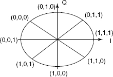
Figure 11.22 8-PSK constellation
The modulating symbol rate is the same as GSM = 1/T = 1 625/6 ksymb/s (that is, approximately 270.833 ksymb/s), which corresponds to 3 × 1 625/6 kbps (that is, 812.5 kbps), where T is the symbol period.
The input bits are grouped into three to make 8-PSK symbols (Figure 11.23) and then Gray mapped and 8-PSK modulated using the following rule:
![]()

Figure 11.23 Generation of the EDGE signal (8-PSK)
The value of l is given in Table 11.5.
Table 11.5 Mapping between modulating bits and the 8PSK symbol parameter l

The 8-PSK rotated symbols are defined as:
![]()
In 8-PSK, symbols are continuously rotated with 3.π/8 radians per symbol before pulse shaping. The modulating 8-PSK symbols ŝi, as represented by Dirac pulses, excite a linear pulse shaping filter. This filter is a linearized GMSK pulse. The impulse response is defined by:

The modulated RF carrier during the useful part of the burst is therefore:
![]()
where Es is the energy per modulating symbol, f0 is the center frequency and φ0 is a random phase, which is constant during one burst. Higher protection is required for 8-PSK, because of the threefold increase in bit rate and the higher number of transition states in the constellation diagram would also result in an increase in the symbol error rate, and thus the increase in the block error rate (BLER). Table 11.6 shows the various MCS used in EDGE. GPRS uses a ½ rate convolutional coder and then employs different amounts of puncturing (removal of bits) to yield a code rate that is appropriate for the channel characteristics. However, EDGE uses a ⅓ rate convolutional coder and selects a puncturing rate that will maximize the net throughput. Here, interleaving is performed over four frames.
Table 11.6 EDGE modulation coding schemes (MCS)

For MCS-9–MCS-5, 1 symbol contains 3 bits and for MCS-4–MCS-1, 1 symbol contains 1 bit. The higher layer PDUs are transmitted in the form of RLC/MAC data blocks, which are different in uplink and downlink directions. The block structures for GPRS and EDGE are different. The blocks are transmitted over four consecutive radio bursts on four TDMA frames of a given packet data channel (PDCH). A 20 ms EDGE radio block consists of one RLC/MAC header and either one or two RLC data blocks (the second part is conditional). In order to support the incremental redundancy feature the header is coded and punctured independently from the data. In GPRS a radio block is interleaved and transmitted over four bursts; each one must be received correctly in order to decode the entire radio block otherwise it needs to be retransmitted.
11.13.1.1Concept of Coding Family
The MCS coding scheme is divided into four families – A, A′, B, and C. Each of this family consists of a set of MCS and associated data unit of fixed size as shown in Table 11.7.
Table 11.7 Different MCS families and associated data unit
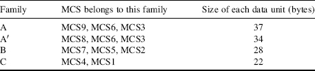
Three block sizes are defined for the nine modulation and coding schemes. This is done to facilitate the re-transmission process. The same MCS (or another MCS from the same family of MCSs) can be selected for the re-transmission of data. Three RLC block sizes and their corresponding MCSs are shown in Figure 11.24. MCS3 and MCS6 are shared between family A and A′ with data unit sizes of 37 and 34 bytes, respectively. MCS7, MCS8, and MCS9 actually transmit two radio blocks over the four bursts and the interleaving occurs over two bursts instead of four. This reduces the number of bursts that must be re-transmitted in errors. When a radio block is sent using MCS9, it consists of four data units of size 37 bytes each. However, when this block needs to be re-transmitted, the MCS3 or MCS6 (as they are from the same family) can be used. Now if MCS6 is used for the re-transmissions, then two radio blocks are required in order to transmit four data units. Hence the data rate is reduced here. Whereas, if MCS3 is used, then four blocks are needed to transfer the data units, for example, a fourfold reduction in data rate.

Figure 11.24 Relationship of the three RLC block sizes to the EGPRS modulation coding schemes
As an example, consider the scenario where MCS9 carries two RLC blocks each of 74 bytes in size. If the signal to interference ratio gets too low or the noise gets too high a transmission error may occur and a re-transmission will be requested. The 74-bytes blocks may then be re-transmitted using MCS6 with one block per four GSM physical layer bursts. If additional coding is required, this can be further segmented into two 37-bytes sub-blocks, and each can be transmitted using MCS3. The header would indicate that this is a segmented portion of a 74-byte RLC block and not a re-transmission using 37-byte blocks. Thus, EDGE provides plenty of flexibility for block-by-block rate adaptation.
11.13.1.2 Incremental Redundancy (IR)
Incremental redundancy (IR), also known as hybrid automatic repeat request (ARQ) type II, is achieved by puncturing a different set of bits each time a block is re-transmitted, thus gradually decreasing the effective code rate for every new transmission of the block. The principle involves the re-transmission of the data block until it is correctly decoded by the receiver. If the receiver fails to decode, it stores the soft bits at the output of the demodulator. Then these bits are used along with the newly re-transmitted bits to decode the next. The re-transmission bits are determined by the puncturing scheme used. The problem with an IR scheme is the memory requirement for storing soft decisions.
11.13.2 Link Adaptation
The dynamic selection of modulation and coding scheme according to the radio link quality is referred to as link adaptation. The EDGE standard supports a dynamic-selection algorithm that includes:
- Downlink quality measurement and report.
- Order for new modulation and coding for the uplink.
Link adaptation, incremental redundancy, and combinations of the two are commonly referred to as link quality control.
The radio link quality is measured in the downlink by the mobile station and in the uplink by the base station. Based on this measured radio link quality, the most appropriate coding scheme for the current prevailing radio channel conditions is determined. Ideally, the MCS can be changed for each radio block but the practical adaptation rate is usually dependent upon the measurement interval.
11.13.2.1 Measurements for Link Adaptation
The decision for which MCS should be used under different radio channel conditions is determined from the measurement report. In the case of GPRS, the decision is based on the parameter RXQUAL (0–7). In EGPRS, a new parameter called the bit error probability (BEP) has been introduced to determine the radio conditions and hence to decide the coding scheme to be used. The BEP is determined on a burst by burst basis and this is used to determine two important parameters: CV_BEP and MEAN_BEP. The CV_BEP indicates the quality from one burst to the other and thus reflects the effect of frequency hopping and the interleaving loss or gain. It is basically a coefficient of the channel quality. Alternatively, the MEAN_BEP indicates the C/I ratio and velocity. It is evaluated by averaging the BEP values calculated on all of the four bursts of a radio block. The MS measures the GMSK_CV_BEP and GMSK_MEAN_BEP or 8_PSK_MEAN_BEP and 8_PSK_CV_BEP and sends the values for the blocks that have been received since the last measurement was sent.
The CV_BEP is computed from MEAN_BEP using the following equation:

The measured BEP values are mapped to different logical values in the measurement report. The reported values of these parameters in the measurement report are mapped from the actual computed mean BEP and CV BEP values using a predefined table.
11.13.2.2 Adaptation Mechanism
The dynamic change of MCS schemes (in the same family) helps to adapt the data rates according to the radio channel conditions. For re-transmission a lower data rate is chosen. One example scenario is shown in Figure 11.25, where an MCS9 data block is re-transmitted using an MCS6 scheme. An MCS9 data block consists of two RLC data blocks of different BSN values, N1 and N2. When this block is split into two MCS6 data blocks, one of these data blocks consists of the first BSN value N1 and the other data block consists of second BSN value N2.
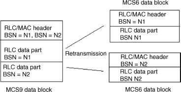
Figure 11.25 Re-transmission of RLC data block for MCS9
11.13.3 RLC Layer
In EGPRS the RLC/MAC layer and the structure of the RLC data block have been modified to support the introduction of new coding schemes and increased throughputs. Some changes have also been introduced in the procedures for TBF establishment in the EGPRS mode. RLC tasks include the segmentation and reassembly of logic link control (LLC) PDUs, LQC (link quality control) and ARQ (automatic repeat request). It is important to correct radio link errors before these are passed up to higher layers. For error free reception, the RLC layer uses selective re-transmission to correct errors. This scheme only requires that erroneous frames to be re-transmitted. The correctly received frames are buffered until the erroneous frame is received correctly and then all the frames are placed in the correct order and sent to the upper layer, which is the logical link control (LLC) layer. Block sequence numbers (BSNs) are assigned in order to complete this reassembly task as well as to detect missing radio blocks.
11.13.3.1 RLC Data Blocks
As mentioned earlier, the RLC data block consists of one header and is followed by one or two data blocks based on the MCS scheme (MCS 7, 8, 9 schemes use two data blocks). Both the data and header part are encoded using different coding schemes but at the same rate. For nine different coding schemes, three header types are defined: (1) header type-1, defined for MCS7–MCS9; (2) header type-2, defined for MCS5 and MCS6; and (3) header type-3, defined for MCS1–MCS4. Headers are different for downlink and uplink. The parameters for downlink header are:
- Temporary Flow Identifier (TFI) – This is a 5-bit field and spread over octets 1 and 2. This identifies the TBF to which the data blocks belong.
- Relative Reserved Block Period (RRBP) – This indicates the position of the uplink radio block on which the mobile should transmit the message.
- Block Sequence Number (BSN) – The transferred data blocks are numbered in-sequence which is known as BSN. For EGPRS this is an 11-bit field. In the case two RLC data blocks carried in the data block, the BSN of the second block BSN2 is encoded relative to the BSN of the first block BSN1.
- EGPRS Supplementary/Polling Bit (E S/P) – This field indicates, whether the RRBP field is valid or not.
- Uplink State Flag (USF) – This was discussed earlier, and is used in the dynamic allocation of the resources to determine which mobile would transmit in the next uplink radio block.
- Power Reduction (PR) – This indicates the power reduction of the current RLC block.
- Coding and Puncturing Scheme – This is used to indicate the coding and puncturing scheme used for the current data block.
- Split Block Indicator (SPB) – This is used in the case of header type-3. It indicates whether the particular data block is segmented and re-transmitted using two data blocks.
In the uplink direction, some of the parameters in the uplink header are the same as in the downlink header. Some other parameters are:
- Countdown Value (CV) – This parameter allows the network to compute the remaining RLC data blocks to be transferred in the ongoing data transfer.
- PFI Indicator (PI) – This indicates the presence or absence of a PFI field.
- Stall Indicator (SI) – The value “0” indicates the window is not stalled, “1” indicates stalled.
- Retry (R) – This indicates whether the channel request message is sent once or more than once in the most recent access request.
- Resent Block Bit (RSB) – This indicates whether an RLC data block has been transmitted previously or not.
The channel coding and burst formation for the MCS1–4 schemes in EGPRS are shown in Figure 11.26. For MCS1–3, first the USF is pre-coded with a block code, and then coded with a convolution code. However, for MCS4, the USF is pre-coded with block code only. The MS can detect the stealing flag and decode the USF from the EGPRS data block, because in all the coding schemes the same stealing flag as the CS4 coding scheme is used. Then 8 bits of the header check sequence (HCS) and 12-bits BCS are added to the header and data part. This is then encoded with the rate ⅓ convolution code. Both the header and the data part are punctured and this results in a data block of size 452 bits. Apart from the 452 bits (comprising of USF, header, and data), there are 8 + 4 = 12 bits stealing flags inserted. Eight stealing flags indicate the coding scheme used, four other extra stealing flags are spread across the four normal burst and are kept for future use and presently set to 0. In the case of MCS7–9, the data blocks contain two RLC data blocks and the USF is pre-coded with 36 bits. The block check sequence of 8 bits for the header and 12 bits for each data part are added. The encoding of the data block is done using ⅓ convolution code and then punctured using different puncturing schemes. The encoded bits are interleaved and transmitted over the air interface.
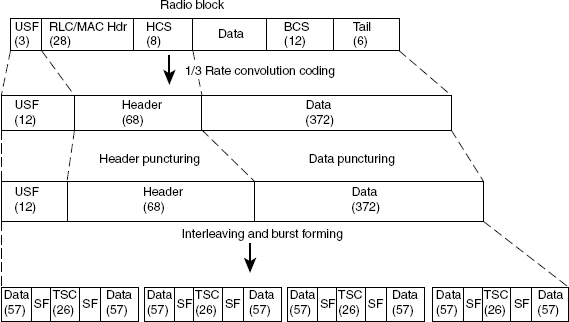
Figure 11.26 Channel coding for MCS1-4 data blocks
As in the GPRS, the CS1 scheme is used to control channels, similarly in EGPRS also the same coding scheme is used for all signaling procedures.
The RLC layer supports two modes of operation.
Unacknowledged Operation:
Unacknowledged operation does not guarantee the arrival of the transmitted RLC blocks and there is constant delay. The receiver attempts to preserve the length of the data blocks it receives. This is useful for real time applications such as video.
Acknowledged Operation:
The acknowledged operation guarantees the arrival of the transmitted RLC blocks. Selective re-transmission is used to re-transmit erroneous data blocks. For each RLC peer-to-peer entity there is a transmit and receive window size established that allows a limited number of blocks to be transmitted prior to receiving an acknowledgement. The window size for EDGE is set according to the number of time slots allocated in the direction of the TBF and ranges from 64 to 192 for single time slot operation or from 64 to 1024 for 8-time slot operation. In GPRS the window size is set at 64.
11.13.4 Data Transfer
Once the PDP context activation has been completed, the data session may begin. Communication between the SGSN and the GGSN is achieved through the use of tunneling. This is the process of adding a header to the existing packet, so that it can be routed through the backbone network. When the packet reaches the far side of the GPRS network, the additional header is discarded and the packet continues on its route based on the original header. The use of tunneling helps solve the problem of mobility for the packet networks and eliminates the complex task of protocol interworking. The GPRS system employs tunneling when sending packets from the mobile station to fixed nodes and also when sending from fixed nodes to mobile stations. This is a distinction from mobile IP, which only uses tunneling in the second case.
11.13.5 Medium Access Control (MAC)
The MAC controls channel access, resource allocation, resource management, and thus enables fixed or multiplexed use of multiple time slots (TS). The MAC layer provides the capability for multiple mobile stations to share the same transmission medium through the use of contention resolution and scheduling procedures. A reservation protocol based on the Slotted Aloha protocol is used for contention resolution among several mobile stations. The MAC layer uses three modes to control the transfer of data in the uplink. The initial mode is specified when the temporary block flow (TBF) is established. The MAC layer assigns temporary block flows (TBFs) for data and signaling transfer between the MS and the network. The TBF is used by each entity to communicate LLC PDUs on the packet data physical channels (PDCH) between the RLC entities on each side of the communication link, as discussed earlier. In general the MAC functionality is similar to that of GPRS. The EGPRS packet channel request message has been defined for initiating the EGPRS data transfer. This is sent on RACH or PRACH. MS specifies its EGPRS capabilities during this message indicating two training sequences. These training sequences are defined in addition to the existing ones. One training sequence indicates that the MS is EGPRS capable and supports 8-PSK in both uplink and downlink directions, while the second training sequence indicates MS is EGPRS capable but supports 8-PSK only in downlink. As for GPRS, if a TBF has to be established in an RLC acknowledged mode, the two phase access procedure is mandatory. For a two phase access procedure, the RLC mode is the acknowledged mode by default.
11.13.6 Impact of EDGE Support on Air Interface and Equipments
The support of EDGE has a direct influence on the design of base stations as well as mobile terminals. New terminals and base station transceivers must be developed that can transmit and receive EDGE-modulated information.
11.13.6.1 Mobile Stations
GSM mobile stations must be designed with the appropriate protocol layers for them to support GPRS and EDGE. They must also be modified to operate on shared traffic channels and the coding schemes must be added. If the MS is EDGE-capable this means it must also implement a new modulation scheme (8-PSK). 8-PSK is a linear modulation type and requires a linear power amplifier. This is especially true for high-output power equipment. Indeed, the designer's challenge is to build a cost-effective transmitter while fulfilling the GSM spectrum mask. EDGE transceiver performance must be acceptable in terms of both transmit spectrum and heat dissipation. Compared with GMSK, the average power decrease (APD) in for 8-PSK could be between 2 and 5 dB. The design of a good sub-optimum equalizer for 8-PSK will be slightly more complex than that of a standard GSM equalizer. The increased bit rate (compared with standard GPRS) also reduces robustness in terms of time dispersion and mobile-terminal velocity.
Today, the GSM standard includes several classes of mobile terminals, ranging from single-slot devices with low complexity to eight-slot devices with high bit rates. EDGE technology has introduced several new classes, with different combinations of modulation and multi-slot capabilities, such as MCS 45 with a maximum number of Rx = 6 and Tx = 6 with sum = 7. There are three classes of mobile stations:
- Class A: Allows for simultaneous use of GPRS/EDGE and other GSM services (such as voice).
- Class B Alternate use of GPRS/EDGE or GSM services is possible. Only one can be used at a time but it is possible to toggle back and forth.
- Class C Designed for GPRS/EDGE only. This class provides no voice service.
The EDGE capable MS is divided into two categories: type-1, which supports both GMSK and 8-PSK modulation schemes in downlink and only GMSK in the uplink direction, whereas the type-2 MS supports both GMSK and 8-PSK in both uplink and downlink directions.
EDGE evolution continues in Release 7 and 8 of the 3GPP standard for providing doubled performance, for example, to complement high-speed packet access (HSPA).
11.13.6.2 Impact on GSM Network Architecture
The introduction of EDGE has very limited impact on the core network, and because the GPRS nodes, SGSNs, and gateway GPRS support nodes (GGSN) are more or less independent of user data rates, no new hardware is required. However, the BTS should support the transmission and reception of a new modulation (8-PSK) and coding scheme. An apparent bottleneck is the Abis interface, which currently supports up to a 16 kbps per traffic channel and time slot. With EDGE, the bit rate per traffic channel will approach or exceed 64 kbps, which makes it necessary to allocate multiple Abis slots to each traffic channel.
11.14 Latest Advancements in GERAN (GSM/GPRS/EDGE Radio Access Network) Standard
11.14.1 EDGE Evolution
The standardization for EDGE (enhanced data rates for global evolution) was finalized by the 3GPP in year 2000. Since then EDGE has achieved market maturity in terms of networks, terminals and business models. Today it offers user bit-rates of around 250 kbps, with end-to-end latency of less than 150 ms. EGPRS2 is a term introduced in GERAN 3GPP Release 7, which specifies a two-level support – level A always refers to the use of the legacy symbol rate (270 833 ksymb/s), whereas level B always refers to the use of the increased symbol rate (325 ksymb/s). Level B will have a more significant impact on the existing network deployments.
EGPRS2 Coding and Modulation: For downlink 16 additional modulation and coding schemes (DAS-5–DAS-12 for 2A and DBS-5–DBS-12 for 2B) and for uplink 13 additional modulation and coding schemes (UAS-7–UAS-11 for 2A and UBS-5–UBS-12 for 2B) are defined for EGPRS2 packet data traffic channels. The Turbo coding is used in downlink only and the scheme of the Turbo Coder is a Parallel Concatenated Convolutional Code (PCCC) with two 8-state constituent encoders and one Turbo code internal interleaver. The coding rate of the Turbo Coder is ⅓. Based on MS feedback, the coding and modulation scheme is adapted to current propagation and signal-to-noise/interference conditions.
Latency Reduction: The latency is reduced by introduction of a reduced transmission time interval (RTTI) and additional protocol enhancements. The blocks are currently transmitted over four consecutive bursts on one time slot using a TTI of 20 ms, whereas in RTTI, it is reduced to 10 ms. In a reduced TTI configuration, a radio block consisting of four bursts is sent using two PDCHs, that is, a PDCH-pair, in each of two consecutive TDMA frames. In a reduced TTI configuration, the time to transmit a radio block is half of a basic radio block period.
Dual Carriers: The introduction of dual carriers doubles the available bandwidth (to 400 kHz) as well as the practical peak bit-rate. Now, this is part of the 2B standard only, and it allows the two downlink carriers to be used simultaneously for one channel. Using dual carriers and five time slots on each carrier provides bit-rates of almost 600 kbps, with no other changes to EDGE.
Dual-Antenna Terminals: By combining signals from the two antennas (mobile station receive diversity, MSRD), a large proportion of the interference can be cancelled out (dual-antenna interference cancellation, DAIC) significantly, improving the average bit-rates and spectrum efficiency. SAIC is a part of the DARP Phase-I requirement, whereas MSRD is a part of DARP Phase-II requirement.
11.14.2 Voice Services Over Adaptive Multi-User Orthogonal Subchannels (VAMOS)
Today, the GSM network is the most successful commercial cellular mobile communication system having more than 3.0 billion subscribers all over the world. It is still growing continuously, because of the growing demand for mobile voice services in emerging markets, especially in China and India, where the subscriber density is very high. As day by day the voice service cost is getting cheaper and new subscribers are registering for the service, this is why most of operators are now facing a real challenge to support so many simultaneous voice calls using limited radio resource.
In the GSM system, the total available physical radio channels in both the directions are: 124 * 8 = 992. Out of these total available frequency carriers, some are used as broadcast frequencies. Thus these usages of physical radio channels limits the number of available traffic channels. During the initial rollout of GSM networks, the main concern was to ensure sufficient coverage at a reasonable cost. Even though coverage is still important, now many networks are limited by the number of users they can serve simultaneously with a sufficient quality. As the capacity of the wireless network increases, the network operators and vendors are challenged to find various creative ways to increase the capacity using the limited spectrum and resources of the network.
One option to accommodate an increased number of users is to introduce smaller cells and a tighter frequency re-use to increase the number of physical channels over a geographical area. However, this approach also leads to higher interference levels and today the capacity of many networks is in fact limited by interference. Smaller cells lead to an increase in the physical channels per user ratio (also lesser transmit power), but as in this case, cells will be closely spaced (more frequency re-use factor), so this will create more co-channel interference. Also, the solution to this situation is the use of the single antenna interference cancellation (SAIC) technique, which is discussed in Chapter 3. Another innovative option is to use the same radio physical channel (frequency, time slot) for multiple users without sacrificing the service quality. The multi-user re-using-one-slot (MUROS) technique originates a new idea to enhance the capacity of both voice and data service.
In MUROS, we create an orthogonal subchannel (OSC), where two users use one time slot with the same ARFCN. The initial idea was proposed by NSN under the name of OSC. It was termed MUROS when it became a study item (SI) by 3GPP. Later, MUROS became a 3GPP work item (WI) at GERAN#40 and denoted voice services over adaptive multi-user orthogonal subchannels (VAMOS), which will be incorporated into 3GPP GERAN Release 9, scheduled for December 2009. An important motivation for MUROS is that it can take advantage of the widely available DARP Phase I capable MS, that is handsets supporting single antenna interference cancellation (SAIC) technology.
Basic Principle: As discussed earlier, DARP was specified to provide improved reception on the mobile station side, when there is co-channel or adjacent channel interference. However, when the downlink signal quality is good, then there is little benefit from DARP. This fact was exploited when the idea of MUROS was conceived, where we intentionally created the co-channel interference scenario in the system by assigning the same physical channel (fTS) to two different mobile stations, as we know that the DARP receiver is capable of interference cancellation. Therefore, in the downlink the network can assign the same physical resources (for example, the same frequency and time-slot combination) to two different mobile stations, but allocates them different training sequence codes (TSC) for channel estimation. As the frequencies of both mobiles are the same, so both these signals will be passed transparently via the RF filter circuits of both receivers, and as these are placed at the same time slot then their energy is just mixed with each other in the channel (own signal with the co-TCH user). This can be treated as a synchronous co-channel interference scenario. Now, each mobile's digital receiver has to use an interference cancellation technique to reject the other user's signal energy from the received signal before decoding. On the uplink each mobile station would use a different training sequence code. The network can use techniques such as joint detection to separate the two users on the uplink.
Introduction of New Training Sequence: The FCCH channel uses FB, SCH uses SB, and RACCH uses AB, and other logical channels, including TCH, use NB. Presently eight different types of TSCs are defined to be used inside NB in the GSM system. Out of these eight, each training sequence code (TSC) is assigned to a cell, and all the adjacent cells must be assigned with different TSCs. The cell BTS number and used TSC are inter-linked and mapped accordingly. The MUROS concept introduces eight (or more) new TSCs (Figure 11.27) in order that each cell can be assigned two or even more TSCs without changing the current frequency planning. Each BSS uses the TSCs to pack two or even more users onto one slot. A BTS is assigned two TSCs, one legacy TSC and one new TSC. These must be low cross-correlated so that receivers can differentiate their own signal from MUROS partners in the same slot, with interference cancelling (IC) technology, such as space–time interference rejection combining (STIRC), successive interference cancellation (SIC) or joint detection (JD) in uplink, or single antenna interference cancellation (SAIC) in downlink.

Figure 11.27 Illustration of cross correlation properties between existing training sequences (solid line) and between new and existing training sequences (gray line)
A number of candidate techniques using a new set of training sequences were proposed for speech capacity enhancement under the MUROS study item. In total seven different sets of new training sequences were proposed by Ericsson, Nokia, Motorola, China Mobile, RIM, and Huawai. The set of new training sequences dedicated to the second subchannel are paired with current training sequences for the lowest cross-correlation with optimal autocorrelation and are listed in Table 11.8.
Table 11.8 Set of new training sequences (TSCs) paired with current ones
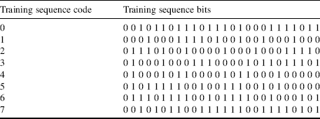
Different Options for VAMOS Support: Four candidate techniques are proposed for VAMOS, but it is assumed that VAMOS will be based on one of the three candidate proposals: OSC, alpha-QPSK or Co-TCH. However, from a terminal point of view the VAMOS signals from these three candidate techniques look similar. Three different types of MUROS modulation schemes for DL signals and their spectrums have been analyzed and these are: (1) linear sum of two GMSK signals (90° phase separation), (2) QPSK with linear Gaussian filter, and (3) QPSK with RRC (roll-off 0.3) filter. The QPSK with RRC filter (roll-off 0.3) spectrum is 10 dB higher than the GMSK spectrum between 140 and 200 kHz. The linear combination of two GMSK signals has the same spectrum (curve overlapping) as normal GMSK signals, as expected. It is within the specification defined GMSK mask for the useful part of the burst. QPSK with a linear Gaussian filter (8PSK pulse shaping) is similar to GMSK. Based on these observations, it is proposed that two GMSK linear combinations and QPSK with a linear Gaussian filter should be the candidates for a MUROS DL modulation scheme.
VAMOS Support for Different Logical Channels: VAMOS allows multiplexing of two users simultaneously on the same radio resource in the CS domain both in downlink and in uplink, using the same time-slot number, ARFCN, and TDMA frame number. The logical channels used for VAMOS are TCH/FS, TCH/HS, TCH/EFS, TCH/AFS, TCH/AHS, TCH/WFS and the corresponding types of associated control channels (FACCH and SACCH).
11.14.2.1 Impact on Various Entities in the GSM System
In theory, MUROS can double the voice capacity (or even more) with negligible impact to the handsets or to the networks. The co-TCH concept requires that one of the two mobile stations must support DARP Phase-I. It is not necessary for the two mobiles to support the new training sequence codes provided the network assigns a different TSC to each of the two mobile stations and these two training sequence codes are not used by neighbouring cells, which use the same frequency (ARFCN).
Impact on Mobile Station
Support of Legacy Mobile Stations: No implementation impacts are required for legacy MS types. The first priority is supporting the legacy DARP Phase-I capable terminals, whilst the second priority is given to supporting the legacy GMSK terminals not supporting DARP Phase-I capability.
Implementation Impacts for New Mobile Stations: For new mobiles it is desirable to support the new TSC set in addition to the existing TSC set so that network has more flexibility in selecting the TSCs. In order to support the use of this new TSC set, radio resource signalling changes would be required. There would be a very minimum impact on MUROS supported MS hardware. Also, the additional complexity in terms of processing power and memory should be kept as minimum as possible.
MS Support Levels for VAMOS: A terminal supporting VAMOS supports a new set of GSM TSC and may be based on either DARP Phase-I or an advanced receiver architecture. Hence two different terminal support levels will be specified for VAMOS aware terminals.
- Level 1: These terminals are basically DARP Phase-I terminals updated to support the new VAMOS TSC set. One major difference between the old SAIC receiver and the Vamos Level-1 receiver is that 8 new training sequences are introduced.
- Level 2: These terminals should have a more advanced RX, fulfilling some tightened 3GPP performance requirements. VAMOS aware terminals will have to indicate their support level to the network in order for the network to exploit the capacity to the highest extent.
Impacts on BSS (BTS and BSC)
The introduction of the candidate techniques proposed under MUROS should change BSS hardware as little as possible and HW upgrades to the BSS should be avoided. For MUROS operation each BTS should have two TSCs. During the channel assignment it should use these TSCs and support the QPSK modulation. When both OSCs are activated, the baseband modulator can take both streams of binary data with two different TSCs applied to the corresponding payload streams, and modulate them in such a way that it satisfies GMSK as defined in the specification, and they are effectively the linear sum of the two independent burst signals that can be well received by legacy mobile stations. In addition, the receiver needs to be able to decode the two GMSK modulated signals that are separated by a TSC. There are a number of BTS receiver techniques that can be employed to provide adequate performance on the uplink, such as duel antenna, joint detection. Abis bandwidth should now be doubled, so that it can carry twice as much as the voice data could before MUROS deployment.
Impact on Radio Resource Management: Radio resource management (RRM) is considered the most vital component in voice capacity enhancement. RRM has to do the following. (1) Determine the most appropriate users to pair together. This may involve the power requirements of each user; the rate of power change, or signal quality. (2) Power control is crucial to providing maximum benefit from the MUROS mode of operation. Power control can allow users with varying channel conditions to be kept in the MUORS mode for longer. Fast power control (that is, enhanced power control) can be valuable for the MUROS mode operation. (3) Determine the most appropriate point to un-pair users.
This has to be a balance between maintaining call quality and spectral efficiency. In order to support pairing and un-paring of users BSS can use existing procedures to move users from one TCH to another (that is, intra-cell handover command or assignment command). It is down to the BSS implementation that is used.
Impact on Network Planning
The impacts on network planning and frequency re-use are minimized. Impacts to legacy MS interfered on downlink by the MUROS candidate technique should be avoided in case of usage of a wider transmit pulse shape on downlink.
![]()
Impacts on the Specification: The impact on specifications is shown in Table 11.9.
Table 11.9 Impact on specification with co-TCH
| 3GPP specification | Impact |
| TS 44.018 – RR signaling | Signaling changes to support new TSC for use with CS connections |
| TS 24.008 | Signaling changes for MS to indicate support for new TSC set |
| TS 45.002 | Defines new TSC set |
| TS 45.004 | Defines new modulation scheme for downlink |
| TS 45.005 | Defines performance requirements for MUROS type modulation |
| TS 51.010 | Defines new performance and signaling tests cases for MUROS capable mobiles |
11.14.2.2 MUROS Basic Operations at the Network and MS Side
Now, in a MUROS supported scenario, when the network assigns a channel to the MS, that time tries to pair up two MSs. Of these two MSs, one should be a VAMOS supported phone and the other one may be a VAMOS supported phone or any legacy DARP supported phone. During the RRC signaling, the MS provides the information about its VAMOS support capability. During the channel assignment, the network will assign the same ARFCN and TS to both the MSs, but to the VAMOS supported MS, it will assign TSC_n1 from the new set and to the old legacy MS it will assign TSC_o1. TSC_n1 and TSC_o1 have minimum cross-correlation properties. This means the first sub-channel can use an existing TSC and the second sub-channel should use the corresponding new one for both downlink and uplink.
The MUROS supported transmission and reception scenario is shown in Figure 11.28.
BTS Transmission: The data from user-1 and -2 are channel encoded (and ciphered individually using A5/1 or A5/3) and then bursts are formed using TSC_n1 and TSC_o1, respectively. Then it is QPSK modulated.

Figure 11.28 Transmission and reception by MS and BTS in MUROS supported scenario
Modulation: Two modulation schemes (GMSK and 8PSK) are supported by the GSM/EDGE system. To introduce an OSC solution in downlink, four points on the 8PSK constellation (Table 11.10) are selected by a BTS transmitter to form the QPSK constellation. The pair symbols from MUROS are mapped, respectively, onto the I- and Q-channels of the QPSK constellation. The first subchannel (OSC-0) is mapped to MSB and the second subchannel (OSC-1) is mapped to the LSB as shown in Figure 11.29.
Support for legacy GMSK MSs can be provided with a modified QPSK modulation. A parameter 0 ≤ α ≤ √2 is chosen to create a quaternary constellation. The constellation is termed an α-QPSK constellation. The extreme values α = 0 and α = √2 yield BPSK constellations, while for α = 1 an ordinary QPSK constellation is obtained. As α changes, the power in the I-channel is changed by 10 log10(α2) dB, relative to the power of the I-channel when using ordinary QPSK. Similarly, the power in the Q-branch is changed by 10 log10(2 − α2) dB relative to the power of the Q-branch for ordinary QPSK. The cross power ratio χ, between the I- and Q-branches, is determined through α as:
![]()
Table 11.10 QPSK symbol mapping on 8PSK constellation


Figure 11.29 QPSK mapping on 8PSK constellation
It is expected that legacy GMSK mobiles will be able to demodulate one of the subchannels, provided α is chosen such that |χ| is large enough. Note that the energy in an α-QPSK constellation is always 1, independent of α. To determine the symbol constellation, that is α, the modulator may receive feedback from the MSs. For example, α may depend upon the reported RXQUAL, or upon the capabilities of the MSs, for example, legacy/legacy SAIC/α-QPSK aware. When an additional rotation is introduced for the α-QPSK modulation, the MS needs to detect it blindly.
A symbol rotation of π/2 can provide subchannels to imitate GMSK. Alternatively, the QPSK signal constellation can be designed so that it appears the same as a legacy GMSK modulated symbol sequence on at least one subchannel, for example, it is legacy compliant. The symbol rotation of π/2 used in downlink allows multiplexing with legacy handsets and alos enables GMSK to be used in the case of DTX and FACCH/SACCH signaling. Different TX pulse shapes may be used in uplink, as proposed for downlink. Whilst the re-use of the GMSK pulse shape is proposed for the initial OSC concept, investigations on an optimized TX pulse in uplink are FFS.
Power Control in Co-TCH MUROS Operation: In the MUROS mode the power given to each user is based on their need, provided that the power difference is within a suitable range (that is, 10 dB) to provide sufficient signal quality for reliable reception by each mobile. From the path loss of each of the two co-TCH mobiles, the required power level P1 for user 1 and P2 for user 2 are derived. Both P1 and P2 are linear quantities. Using P1 and P2, obtain the I-Q amplitude ratio of the two users as follows:
![]()
Determine the digital gains for each of the two co-TCH mobiles: for user 1, G1 = cos(α), and for user 2, G2 = sin (α), where α = arc tan(R) and α![]() [0, π/2].
[0, π/2].
MS Receiver: Generally, single antenna interference cancellation (SAIC) is used in the receiver. As discussed earlier, the legacy MS should support DARP and will cancel the interference using SAIC algorithm without any change to the existing system. However, the VAMOS supported receiver requires some changes in the receiver architecture to support QPSK de-modulation and new TSCs. Assume that tk and ck are two TSCs of the two MUROS subchannels. The two sequences are in-phase with the corresponding binary subchannel symbols. The discrete signal of the TSC part at the receiver side is:
![]()
Correlation is the general operation at the receiver side for channel estimation. The correlation of received rk with TSC tk yields:
![]()
The first item on the right-hand side is the desired channel response. The second item relates the autocorrelation of TSC tk with delay. The third item of is related to the cross-correlation between the two subchannel TSCs. Usually good TSC will ensure the second and third items to be zero.
The VAMOS receiver chain co-exists with the existing DARP receiver chain. In the VAMOS receiver chain, first the received samples are de-rotated by −π/2 radian per symbol, which is identical with the GMSK signal complex input signal rotation. Then the TSC part is passed through the α-QPSK detector, and VAMOS constellation points for calculation of the complex valued α-QPSK constellation points that correspond to the VAMOS training sequence symbols for a particular α-value. Each training sequence symbol is identified by a bit pair b1b0 where b1 is the bit from the desired user training sequence and b0 is the bit from the orthogonal user training sequence (both bits ![]() {0, 1}). This module should be made general, so that both the desired user training sequence and the orthogonal user training sequence can be any of the legacy GMSK training sequences and any of the new training sequences for VAMOS. Next, burst timing (using maximum energy) is performed and enhanced channel estimation is done to find out the channel taps. The rotated and frequency corrected whole burst and the channel taps are passed to the equalizer unit for equalization. The softbits of user 1 and user 2 are generated and then the noise variance scaled user 1 softbits are passed for decoding.
{0, 1}). This module should be made general, so that both the desired user training sequence and the orthogonal user training sequence can be any of the legacy GMSK training sequences and any of the new training sequences for VAMOS. Next, burst timing (using maximum energy) is performed and enhanced channel estimation is done to find out the channel taps. The rotated and frequency corrected whole burst and the channel taps are passed to the equalizer unit for equalization. The softbits of user 1 and user 2 are generated and then the noise variance scaled user 1 softbits are passed for decoding.
MS Transmitter: Modulation (that is, GMSK) and burst structure (normal burst) are the same as for legacy traffic channels. Each MS uses GMSK modulation for burst transmission. Inside the normal burst, the legacy MS uses the old TSC, whereas the VAMOS supported MS uses the new TSC, which is assigned by the network during the RRC signaling.
BTS Receiver: For compatibility reason, UL OSC allows MS to use a normal GMSK transmitter with good cross-correlation properties. IC technology is necessary at a BTS receiver to detect signals of the MUROS pair simultaneously (Figure 11.30). It is assumed that BTS uses, for example, an STIRC or SIC receiver to receive orthogonal subchannels used by different MSs. A BTS receiver may use, for example, successive interference cancellation (SIC) or joint detection (JD) to receive signals from two mobiles on simultaneous subchannels with individual propagation paths. Thus, the uplink scheme can be seen as a 2 × 2 multi-user MIMO, where different propagation paths from two users provide the basis to fully utilize the degree of freedom of two receive antennas in a typical BTS.

Figure 11.30 BTS receiver processing
SIC is a process of multi-user detection (MUD), when the SIC receiver detects signals of several users, it will demodulate them in decreasing order of signal power. The strongest signal is detected and demodulated first, and then removed from the mixed signals, then it is the second strongest signal, and so on. The detection algorithms for SIC receiver are zero forcing (ZF), minimum mean square error (MMSE), and so on. The MMSE method could be adopted by the BTS receiver with two or more receive antennas. Let x be the transmitting signal, and ![]() be the estimated signal, and r be the received signal, the criterion of the MMSE algorithm is illustrated as follows:
be the estimated signal, and r be the received signal, the criterion of the MMSE algorithm is illustrated as follows:
![]()
where ε2 is the mean square value and W is the weighted matrix.
MUROS should be considered as the potential feature for future GERAN evolution capacity improvement, due to its ability to double the capacity of GSM/EDGE networks without degrading the speech quality very much. In particular, a voice quality better than for GSM HR should be ensured.
Further Reading
3GPP TS 45.002. GPRS Logical Channels and Mapping to Physical Channels. ETSI TC-SMG, Sophia-Antipolis Cedex.
3GPP TS 45.003. Specifies the Channel-Coding Rules for Different Logical Channels. ETSI TC-SMG, Sophia-Antipolis Cedex.
3GPP TS 45.004. 8-PSK Modulation for EDGE. ETSI TC-SMG, Sophia-Antipolis Cedex.
3GPP TS 45.008. Radio Sub-System Link Control. ETSI TC-SMG, Sophia-Antipolis Cedex.
3GPP TS 44.060. RLC/MAC layer and Signaling Pprocedures. ETSI TC-SMG, Sophia-Antipolis Cedex.
3GPPTS 43.064. GPRS/EDGE air Interface and RLC/MAC Procedures. ETSI TC-SMG, Sophia-Antipolis Cedex.
Grant, S.J. and Cavers, J.K. (2008) Performance enhancement through joint detection of cochannel signals using diversity arrays. IEEE Trans. Commun. 46, 1038–1049.
Klang, G. and Ottersten, B. (2002) Space-time interference rejection cancellation in transmit diversity systems. Paper presented at The 5th International Symposium on Wireless Personal Multimedia Communications, 2, 706–710.