
11
Property Model Methodology Development Process
11.1. Introduction
In this chapter, we will describe the system development process promoted by the property-model methodology (PMM). In order to introduce this process, we will first describe its upstream environment. And then, we will present the different steps of such a development. Then, we will describe each step in detail and, to conclude, we will discuss issues related to configuration management and collaborative work within the framework of the PMM.
11.2. Early phase of a system development, preliminary studies
Developing a new type of systems is usually preceded by a preliminary studies phase. During this preliminary studies phase, we first consider the practical and economical interests of these type of systems. Second, the feasibility and efficiency of such a type of systems is also assessed. The aim is not, at this step, to work through a systems industrial development process, but to highlight the operational environment conditions, operational goals, operating principle of the new type of systems and an associated operational concept. However, if the type of systems under consideration is derived from precedent type of systems, which already exists, this preliminary study phase can be reduced to a re-evaluation of the parameters taken into account during the initial preliminary studies. During these studies, it is not rare to set up simulation methods and develop models. This preliminary studies phase is not covered in the framework of PMM, but it would not be without interest that models drafted during the phase be industrialized in the framework of the system development.
If, for example, these preliminary studies relate to a midair collision avoidance system (CAS), installed in an aircraft, these studies will first be focused on the conditions of midair traffic, namely the traffic density of the different air-space zones. This is done to appreciate the risks of collisions, today and tomorrow, in relation to the foreseeable evolution of traffic, the inacceptable, or not, character of these risks, and to define the safety objectives capable of containing these risks within socially acceptable limits. The preliminary studies will have to characterize the goal of the type of systems, namely, enable the avoidance of aircraft collisions in the air, with a success rate compatible with the safety objectives. Preliminary studies will then consider operational strategies (detection, place of operators in the loop, warning operators, coordination between aircraft involved and characterization of avoidance maneuvers) by plugging them into operation scenarios. The efficiency of these strategies will have to be evaluated with regard to (1) the safety objectives and (2) the available midair collision data or risky situation data, while the situations exhibiting flaws in these strategies will be identified. The preliminary studies will have to identify the resources that are necessary and available to carry out these strategies, as well as the impact of deploying such a new type of systems on the operators, in operational and organizational terms.
Preliminary studies can be concluded with an operational1 and maintenance concept, which the industrial development of the type of systems under consideration can be based on.
11.3. Steps of the industrial development of a type of systems
The concepts of operation and maintenance provide a possible entry point to the industrial development of the type of systems under consideration. The PMM covers this industrial development, from a methodological perspective, by decomposing it into different steps as illustrated in Figure 11.1.
Figure 11.1. PMM system development process
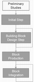
The following steps are prescribed by the PMM:
In the following sections, we will describe these different steps by identifying the different activities and fail/pass criteria for each step.
Figure 11.2. Colossus with feet of clay in Nebuchadnezzar’s dream

11.4. Initial step: highest level system specification
The highest level system specification is the cornerstone of a descending development process of a type of systems. It provides the reference for the whole of the development. Consequently, it also concentrates the maximum risk of transforming development into a “colossus with feet of clay2”. If the system specification is not carried out well, blurred, incorrect or incomplete, we can fear that the resulting systems will be unsuitable to the needs, that their development costs will strongly surpass the objective costs and that the provision deadline will not be respected.
11.4.1. Initial step general approach
The proposed approach for this first step aims to reduce the risks, although it cannot be completely eliminated. It is described according to the following six points:
11.4.2. Establishing a specification model of the type of systems
Specifying a type of systems Σ according to the PMM approach involves constructing specification models. It is a gradual development process of the system model that can require multiple iterations based on the understanding that it is better to quickly dispose of a crude (“false”) model to then rework it, rather than suffer the absence of a model. Simulation can, therefore, be a means to adjust the specification model, which will progressively mature through successive improvements.
Figure 11.3. System specification model. For a color version of this figure, see www.iste.co.uk/micouin/MBSE.zip
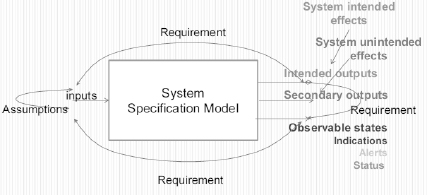
According to PMM, a type of systems is specified by its outputs. It is useless to progress any further as long as we do not know what output the system has to produce.
Thus, the first thing to do is to focus on the effects it shall produce on its environment, that is to say its functions (see section 2.3, Function=Intended Effects of a system). We can determine them by, for example, considering the results of preliminary studies and the operational concept that comes from it. We must temporarily forget the inputs, we will return later. Focusing on outputs, we must ask questions such as: (1) what kind shall these outputs be (matter, power, data or events flows)? (2) do these flows have to be continuous or discrete? (3) what are the rates at which these outputs shall be produced? (4) if so, what rate of change in these outputs shall be ensured? We can at the same time, or later, be brought to specify the failure conditions (see section 10.3.2) such as the loss of one or more outputs and detected error outputs (what of the undetected error outputs?).
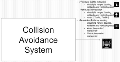
For example, if we specify a collision avoidance type of systems, installed in an aircraft to prevent midair collisions, the first thing to do is to determine the intended outputs of the systems: these outputs can be (1) visually indicate the crew of the aircraft equipped with a CAS, all aircraft within its immediate vicinity, (2) visually warn the crew and emit an aural warning when an intruder aircraft is closer, finally (3) suggest the crew an avoidance maneuver if the risk of collision is found. In addition to the functional outputs specification, we can imagine the specification of a CAS observable state, including, for example, failure codes. Then, the question of knowing how many intrusions the system shall be able to take into account concurrently comes? This being set, we know what the system shall do.
Figure 11.4. CAS specification model of intended functions. For a color version of this figure, see www.iste.co.uk/micouin/MBSE.zip
The outputs being defined, we can now focus on the conditions the outputs shall be performed in. There are multiple kinds of conditions. These could be, for example, an output must appear within a given timeframe after the occurrence of an input, and this output must be a function of the input. Another possibility is that an output must appear within a given timeframe after the occurrence of an observable state, and this output is a function of the observable state under consideration. We can multiply, as needed, the appearance conditions of an output and its current value. That is to define the inputs or the observable states linked to the outputs by property-based requirements.
For example, if we specify a type of CASs installed in aircraft to prevent midair collisions, the outputs having already been identified, we shall specify the appearance and disappearance conditions of a (1) close traffic indication, of a (2) traffic warning and, of (3) a caution associated with a conflict resolution advice, and all those conditions depend on a representation of the aircraft local environment, elaborated by the system. This local environment representation constitutes an observable state of the model that conditions its outputs and shall be as exact as possible.
Figure 11.5. CAS protected, volume and local environment representation. For a color version of this figure, see www.iste.co.uk/micouin/MBSE.zip
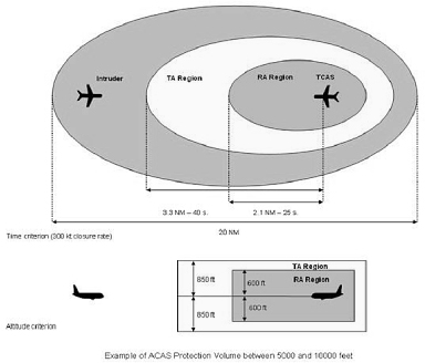
After this, we are brought to ask ourselves the same questions about the observable states as the ones asked about the outputs, that is to say, what their appearance and elaboration conditions are. For example, if we specify a type of CASs installed in aircraft to prevent midair collisions, the outputs having already been established, we will specify the elaboration and conditions of the local environment representation the system builds. This representation of the local environment is elaborated from inputs, from the CAS carrier aircraft and from aircraft located in the CAS carrier aircraft close environment.
Once the outputs and observable states have been taken care of, the case of inputs remains. What is the nature of the inputs, are they material flows, energy flows or even information flows? Are these flows continuous or discrete? What are the magnitudes or definition domains? What are the flow rates or the highest frequencies of these inputs? What are the logics of appearance or disappearance of these inputs? If relevant, what are the variation rates of these inputs? As these inputs come from the environment, we do not have control over them. In this case, we do not formulate requirements but assumptions (that are formally identical but very different in practice).
For example, for a CAS, these inputs can be a number of physical aircrafts with their own kinematics (position and speed). We will, therefore, formulate assumptions on (1) the maximum number of aircrafts that can be taken into account by the CAS, (2) the accessible information concerning these aircraft. Thus, we obtain assumptions on the available inputs of the type of systems and conversely the operational limits of this type of systems. We will also be able to imagine a CAS, based on the data provided by an automatic-dependent surveillance-broadcast (ADS-B)3 system, as an input assumption.
Once the outputs, observable states and the inputs of the type of systems to be developed are identified, the relationships, which shall exist, between them shall be specified. In other words, how the outputs shall be devised as functions of the observable states and/or inputs. In which circumstances shall an event appear as an output, as a function of which input events? How shall the value of an output be devised from the value of the inputs and/or observable state? What shall the temporal inertia of the type of specified system be? What maximum delay can it introduce between the coming of the inputs and the appearance of the outputs?
For example, for a CAS, the specification of the relationship between the inputs and outputs can be the following:
Figure 11.6. CAS specification model PBRs. For a color version of this figure, see www.iste.co.uk/micouin/MBSE.zip
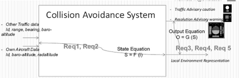
This gives us six property-based requirements:
PBRa: when CAS_Engaged and inGreen_Envelop(NewIntruder) → AdditionalIntruderDataDisplayed
PBRb: when CAS_Engaged and inGreen_Envelop(Intruders) → IntruderPositionDisplayUpdate
PBRc: when CAS_Engaged and goesoutGreen_Envelop(Intruder) → IntruderPositionDisplayCanceled
PBRd: when CAS_Engaged and inYellow_Envelop(Intruder) → TA_Displayed and Aural(“Traffic, Traffic”)
PBRe: when CAS_Engaged and inRed_Envelop(NewIntruder) → RA_Displayed and Aural(Avoidance_Maneuver)
PBRf when CAS_Engaged and goesoutRed_Envelop(Intruder) → Aural(“Clear of conflict”)
The terms appearing in this specification model all refer to a state (a value of a property) of the targeted type of systems. This is what we named the semantic assumptions (see section 4.3) of a model.
SA1: CAS_Engaged: the CAS system is installed and engaged
SA21: inGreen_Envelop(NewIntruder): a new aircraft has been detected in the external (green) envelope
SA22: AdditionalIntruderDataDisplayed: the characteristics of the last aircraft detected in the external (green) envelope are visually presented to the crew
SA23: inGreen_Envelop(Intruders): the characteristics of the aircrafts detected in the external (green) envelope evolve
SA24: IntruderPositionDisplayUpdate: the visual presentation, intended to the crew, of the characteristics of the aircraft detected in the external (green) envelope is updated
SA25: goesoutGreen_Envelop(Intruder): an aircraft leaves the external (green) envelope
SA26: IntruderPositionDisplayCanceled: the visual presentation, intended to the crew, of the characteristics of the aircraft detected in the external (green) envelope is deleted
SA31: inYellow_Envelop(NewIntruder): a new aircraft has been detected in the intermediary (yellow) envelope
SA32: TA_Displayed: a visual Traffic Advisory alert is emitted for the crew
SA33: Aural(“Traffic, Traffic”): the aural alert “Traffic, Traffic” is emitted for the crew
SA41: inRed_Envelop (New Intruder): a new aircraft has been detected in the internal (red) envelope
SA42: RA_Displayed: a visual Resolution Advisory alert is emitted for the crew
SA43: Aural(Avoidance_Maneuver) : the aural alert indicating the type of maneuver to be carried out is emitted for the crew
SA51: goesoutRed_Envelop(Intruder): an aircraft leaves the internal (red) envelope
SA52: Aural(“Clear of conflict”): the aural alert indicating the end of the conflict is emitted to the crew
Of course, this specification is objective but it is not necessarly exact. It shall be validated.
Finally, we know that a system does not only produce intended effects but it can also produce undesired effects, which we will seek to limit, false alarms on one hand, but also other unwanted events on the other hand (see section 10.3), in order to make them tolerable or acceptable.
11.5. Design steps: descending and iterative design of the building blocks down to the lowest level blocks
Once we have a specification model of the type of systems under consideration that is sufficiently exact (in other words, validated as indicated above), it is possible to start the design phase, which is decomposed into different design steps by obeying the following rules:
11.5.1. Design step of a non-terminal block
In case we have a clear vision of the behavioral chain to be set up in order to satisfy the requirements allocated to a non terminal block, a design step of this block can, straightaway, be limited to a structural design, so long as we dispose of a validated specification model for that block.
11.5.2. Behavioral design step of a terminal block
We consider a block to be terminal (a block of the lowest level) within a system decomposition when it (1) is available off the shelf of a supplier (this is the case for, for example, with sold equipment with an approbation letter (TSO/ETSO)), (2) is developed to satisfy defined specifications by a supplier and (3) can be directly made without any additional design. We recall also, that an equation-based model design is a terminal behavioral design model.
A behavioral design step of a lowest level block can start from the moment we dispose of a validated specification model of that block.
11.5.3. End of the design step
The design phase ends with the verification of various level of integration of the system model ascending order design templates terminal blocks to model the complete system. This activity is fully described in section 9.3.3.
11.6. Realization step of the lowest level building blocks
The realization of a lowest level block can be subdivided into two substeps:
11.7. Integration and installation steps
The integration of a type of systems is an iterative and ascending process ending on an installation final step, which is composed of two substeps:
11.8. Conclusion
The development process we have described in this chapter allows mastering and sharing of the design and development workload, for a type of systems, so long as it clearly identifies the steps from which the workload can be shared between multiple separated teams, and performed in parallel. These sharing steps are specified in the introduction of section 11.5, indent 2 and 3, which provide the independence and dependence rules allowing the parallel set up of the workload, while the contract theorem, stated in section 9.3.5 ensures the correct integration of workloads carried out in parallel. Additionally, the development process proposed gives us the possibility to manage, in parallel, multiple different versions of the specification models and design models of different constituents of a building block, and therefore to configure the type of systems under consideration according to different clauses, which all ensure the same system-level requirements.
1 IEEE Std 1362–1998, IEEE Guide for Information Technology – System Definition – Concept of Operations (ConOps) Document.
2 “32-Then was the iron, the clay, the brass, the silver, and the gold, broken to pieces together, and became like the chaff of the summer threshingfloors; and the wind carried them away, that no place was found for them” Daniel, Chapter 2–32.
3 ADS-B = automatic-dependent surveillance-broadcast.