
Appendix
A1.1. Introduction
The purpose of this Appendix is to propose elements to translate system models (SMs) following the property-model method (PMM) methodology into a simulation model that allows us (1) to validate the specification models, (2) to verify the PMM design models and (3) to prepare the underlying phases of verifying the realization (single physical verification, physical integration and installation verifications).
In section A1.2, we will discuss roles introduced by the PMM methodology, namely the roles of the specifier, designer, validator and verifier. We will also mention the means required to perform PMM activities, namely the front-end of modeling used by specifiers and designers and the back-end of simulation, for validators and verifiers.
In the next sections, we will cover the modeling of a system specification and modeling of different design models. In section A1.3, we will consider the declaration and definition of specification model ports as well as the declaration and definition of property-based requirements (PBRs), which are also included in a specification model. In section A1.4, we will consider the declaration and definition of different design models associated with a given specification model, namely equation design models, behavioral design models (BDMs), structural design and reliability design models (RDMs). For each of these models, the required resources are identified. The Appendix concludes with section A1.5, on the configuration of an SM using different building blocks (root, intermediate and terminal) that can compose it; each of them is an assembly of a specification and design model. The transformation of an SM into a simulation model allows us to, depending on the different configurations considered, guarantee the validation of a specification model, the verification of a design model and also to assess the efficiency of failure prevention or mitigation mechanisms.
A1.2. Roles and means
A1.2.1. Roles
The PMM methodology identifies, a priori, four main roles in the development process of a type of systems. This includes the following conceptual roles:
These four conceptual roles may be played by the same physical person or, on the contrary, by different physical persons of the same or different organizations depending on the availabilities and the level of independence defined in the validation and verification plans.
Additional roles may be considered, for example, a workbench administrator whose role is to continuously maintain a description of modeling and simulation tools, the recording of the problems and the evolutions for qualified tool (or not) to ensure the production of certifiable systems once installed (for tool qualification refer to ED124/DO-297) [ED 07].
A1.2.2. Means: an environment for modeling and simulating
To carry out a development process according to the PMM approach, a project team should have a modeling and simulation environment.
This environment may be logically divided into two parts, the front-end and the back-end, even if it can be a physically integrated environment.
The first part, the front-end, allows the specifier and designer to develop specification and design descriptions models. It also allows system models to be configured from specifications and design descriptions previously modeled as building blocks.
It also allows the validator and the verifier to prepare validation processes (of specifications) and verification processes of different developmental steps (the design verification as first step), according to two axes (1) by designing a validation bench (respectively, a verification bench) and (2) by selecting the validation cases (respectively, verification cases) and the validation scenarios (respectively, verification cases).
Figure A1.1. PMM workbench conceptual design. For a color version of this figure, see www.iste.co.uk/micouin/MBSE.zip

The second part of the development environment, back end, allows the validator and verifier to validate specification model and verify design models.
Many simulation environments on the market, based on simulation languages such as VHDM-AMS or even Modelica, may implement the back-end of PMM methodology; however, we do not know of an environment on the market capable of implementing the front-end, given the novelty of concepts such as those of the specification model or PBRs.
It is, therefore, a characterization of this front-end, which we will focus on below.
Figure A1.2. Front-end main window and views on PMM models. For a color version of this figure, see www.iste.co.uk/micouin/MBSE.zip
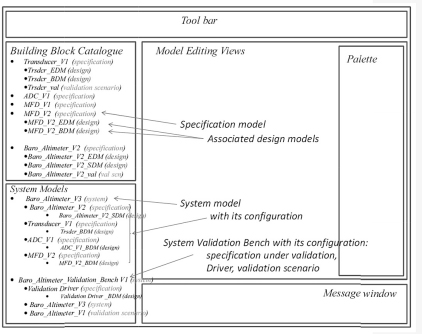
Figure A1.2 gives one possible view of the main editor, as well as a view on the database of PMM models (middle part of Figure A1.1) on the left part of the editor (Figure A1.2).
The left part of this main editor gives a view on the two categories of objects:
In the catalog of building blocks, the following are listed: (1) specification models and (2) design models associated with different types (EDM for equation models, SDM for structural models, BDM for behavioral models and RDM for reliability models). For example, we can see that there may be several versions of a specification model (for example, MFD_V1 and MFD_V2). The design models are secondary entities relatively to a specification model, which they are attached. Design models are associated with this specification model, such as an equation design model (EDM) that validates and exactifies the specification model from which it originates. Also associated are a number of behavioral design models (BDMs) that describe different architectures and behavioral solutions and even a number of structural design models (SDMs) representing different architectures and structural solutions, to continue to decompose the model. We can then associate reliability models with these structural models to assess the conformity of design solutions to safety requirements. A specification model, associated with a set of design models, defines several variants of a building block.
In the bottom part, the following are listed: (1) SMs, with for each, the constituting building blocks, as well as (2) validation and verification bench models (which are only specific SMs with which data are associated: scenarios and validation or verification cases listed in files, execution traces of validation or verification scenarios).
A1.3. Producing a specification model (SSM)
Figure A1.3. PMM specification view
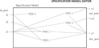
Specifying the requirements and assumptions assigned to a type of systems by a specifier is carried out using a PMM editor, which has a type of systems associating a certain number of characteristics among which are found:
A1.3.1. Ports
The ports of a specification model are of three types: they may be input ports, output ports or even observable ports. In the logic of PMM (which is also that of block diagrams), an input represents a cause, whereas an output represents a visible effect of a type of modeled systems. Finally, an observable is a probe that the specifier uses to observe internal states of the SM.
Moreover, ports have a nature and a type. A port may be of a continuous nature or of a discrete nature. This allows us to characterize the quantities that flow through these ports. Thus, ports allowing quantities related to a fuel flow, crossing the borders of a fuel system, may be considered as continuous ports, while electronic signals will pass through discrete ports. In addition, ports shall be typed. Thus, continuous ports are either of the real type or a composite type where each component is real. Discrete ports have a more extensive typology. They may be scalar (enumerative, integer or real) or composite (homogenous: arrays, or heterogeneous: records).
If, for example, we consider a fuel system, then the fuel flow rate, required by the engine(s) at a given moment, may form a continuous input (i.e. a cause) of a fuel system, whereas the pressure at which the fuel is supplied to the engine(s) may be a continuous output (i.e. an effect) of the fuel system to respond to the engine demand. The specifier may also introduce an observable that helps us know the actual fuel quantity contained in the fuel system. However, this observable will not be confused with a fuel level indication (required by the regulation) that should be processed as an output, since it corresponds to an effective output, not only of the model, but also of the physical corresponding systems (whereas an observable does not correspond necessarly to the output of a system).
A1.3.2. Property-based requirements and assumptions
The PBRs of a specification model are declarations of links between the ports of a specification model. A PBR can link one or many ports together. We can subdivide these PBRs into two classes, assumptions and system requirements:
Each PBR will not only be declared, but also defined, that is to say it will be expressed in a non-ambiguous language, which can be compiled (after an eventual transformation) and whose compilation result can be executed in a simulation environment. For this, there are three possibilities: (1) to define a specific PBR modeling language with the required properties, (2) to directly use the simulation language to express the PBRs and (3) to provide a (graphical) support allowing the PBRs to be defined.
Figure A1.4. Function and PBR graphical editor
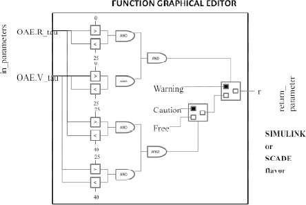
Figure A1.4 represents a means of defining a PBR (and more generally, a function) using a graphical editor inspired by graphical editors such as those provided by SIMULINK or even by SCADE. However, specifiers not put off by a textual formalism should be able to directly access a PBR model, either to create it or to modify it (particularly during the PBR validation phases). Figure A1.4 is a graphical representation of the definition of a function. For the definition of a PBR (that is only ever a Boolean function), the function inputs correspond to the ports that are linked to each other by PBR in the declaration at the specification model level. The connection between inputs and outputs is established by using different types of connectors (logical, algebraic, comparative, operational conditional and iterative, functional, temporal, etc.) that link them to varying or constant quantities. These graphical connectors are available and accessible via palettes.
A1.4. Producing design models
Producing design solutions associated with a specification model may be carried out in four different ways. The first involves producing an EDM from the specification model. The second involves developing a BDM that implements a behavior model for the type of systems. The third involves the decomposition of a system into an SDM composed of a certain number of components linked together and to ports of the SM by links. Finally to carry out reliability studies, the fourth involves designing RDMs. As there is no formal difference between an SDM and an RDM, the latter will not be discussed below.
A1.4.1. Equation design models
EDMs were introduced in section 7.4.2. An EDM is a design model whose purpose is to allow the validation of a specification model. It is, therefore, based on a transformation that moves from a PBR to its dual: a design equation.
The schema for generating design equations is based on the fact that the most general form of a PBR is an expression.
Req: when C => O.P ∈ D.
An equation derived from this PBR will, therefore, be in the following form:
Eq: O.P:= x ∈ D when C.
In other words, assign to the property O.P any value x(that can be chosen randomly if needed) belonging to domain D when condition C is verified.
Figure A1.5. Equation design model view
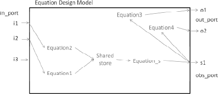
However, some PBRs may not give rise to any equation in the EDM model; this is the case for assumptions, as they are not produced by the system but by the environment. This is also the case for all coherence controls that may be defined by outputs or observables (for example, the fuel pressure at the output of a fuel system will not exceed 3.0 bars) and that are nicely expressed in the form of a PBR.
Other PBRs may require a slightly more complicated generation schema than the base schema shown above. In particular, this is the case when two or more inputs can independently affect an output or an observable. In this situation, several input flows (of information, matter or energy) converge toward the same system output. In this case, it may be necessary to control the access conditions of flows entering a shared resource, which itself feeds the output. This is what is illustrated by the EDM in Figure A1.5 on which two equations (equations 1 and 2) converge both on the same shared resource.
A1.4.2. Behavioral design model
As mentioned in section 7.4.1, the second type of behavioral model (alongside equation models) is provided by the BDM.
A BDM is developed, by a designer, based on a validated specification model.
Figure A1.6 illustrates how this can be a graphical representation of a BDM.
Figure A1.6. Behavioral design model view
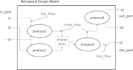
This figure shows the following features:
These features of a BDM can be declared and interconnected using graphical patterns selected on a palette.
The processes of a BDM have ports defined in the same way as ports of a specification (nature, type and direction). These ports link processes to external ports, to other processes or even to shared resources by flows. These links formed by flows will be consistent in nature, type and direction for ports and in nature and type for flows.
The processes may be discrete, continuous or hybrid:
Shared resources allow discrete or hybrid processes to consistently synchronize and exchange quantities, as required, by operators accessing resources.
Flows connect either ports of the specification model to internal processes (external flows), or internal processes between them (internal flows), or internal processes to shared resources (and vice versa). Note that a flow can have several destinations but one single source.
Once declared (using a BDM editor), the processes composing such a model will be defined.
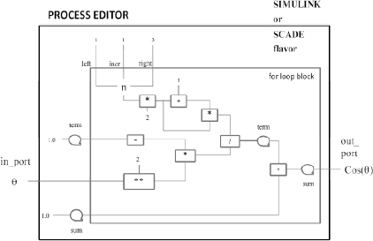
Figure A1.7. Process graphical editor
As with PBR, each process will not only be declared (using the BDM editor) but also be defined, that is to say, it will be expressed in a non-ambiguous language, which can be compiled (after an eventual transformation) and whose compilation result can be executed in a simulation environment. For this, there are three options: (1) to define a specific modeling language for the process description, which has the required properties, (2) to directly use the simulation language features to define these processes and (3) to provide a (graphical) support allowing the processes to be defined.
Figure A1.7 shows how to define a process using a graphical editor inspired by graphical editors such as those provided by SIMULINK or even by SCADE. However, designers not put off by a textual formalism should be able to directly access a process model, either to create it or to modify it (particularly in the verification phases of the design model).
This figure is a graphical representation of the definition of a process computing cosine of an angle θ using a MacLaurin series up to order 6. To define a process, the process input ports are linked to obsrevable or output ports using different types of connectors (logical, algebraic, comparative, operational conditional and iterative, functional, temporal, etc.) which also connect them to (1) constant or varying quantities, local to the process, or eventually to (2) shared resources. These connectors are available and accessible via palettes.
A1.4.3. Structural design model
As mentioned in section 7.6, the PMM methodology defines two kinds of static model. The first kind includes SDMs, while the second kind is described in the next section.
An SDM is developed, by a designer, based on a validated specification model. These design models with their characteristics were discussed in section 7.6.2.
Figure A1.8. Structural design model view
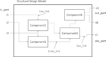
Figure A1.8 provides an illustration of a graphical representation of an SDM.
This figure shows:
The characteristic features of an SDM can be declared and interconnected using models selected on palettes.
The components of an SDM have ports defined as with specification ports (nature, type and direction). These ports allow us to connect the component to external ports, to other components by means of links. These links will be consistent in nature, type and direction for ports and in nature and type for links.
The links connect either ports of the specification model to component ports – these are external links –, or component ports together – these are internal links. Note that a link may have several destinations but one single source.
Components of an SDM are receptors designed to receive building blocks; therefore, the specification model has exactly the same ports as those of the receptor component. A component is, therefore, a kind of placeholder designed to be linked to a building block during the configuration of an system model (SM) (see section A1.5).
A1.4.4. Reliability design model
In PMM, the second type of structural model is the reliability design model (RDM).
An RDM is developed, by a designer, in reference to an SDM. These reliability models and their characteristics were presented in section 10.3.6.
These models do not introduce additional syntactical elements with regard to an SDM editor.
A1.5. Producing a system model (SM)
Figure A1.9. System model and specification and design tree. For a color version of this figure, see www.iste.co.uk/micouin/MBSE.zip
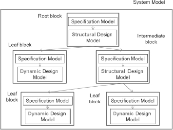
In PMM, an SM is a particular assembly (a configuration) of a set of building blocks, structured like a tree.
An SM is, therefore, composed of a root block linked to zero or at least two successor blocks.
If the root block is without a successor, then it is ultimately composed of a specification model and a behavioral model (EDM or BDM).
Whatever is true for the root block (without successors), is also true for any leaf block (i.e. without successors). A leaf block is composed of a specification model and a behavioral model (EDM or BDM). The behavioral model associated with the specification model of a leaf block is one of the design models associated with this specification and is available in the block catalog. Therefore, all that is required is to select it using a “drag & drop” operation in the SM editor.
With regard to an intermediate block (it has successors) or the root block (if it has successors), such blocks are inevitably composed of a specification model and a structural model (SDM or RDM).
As these structural models contain at least two components1, it is therefore necessary to link these components with building blocks residing in the building block catalog, as shown in Figure A1.10.
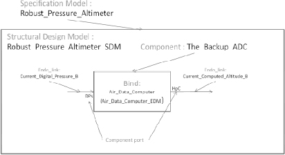
In this example, the SM Robust_Pressure_Altimeter consists of a specification model (Robust_Pressure_ Altimeter) and an SDM (Robust_Pressure_Altimeter_SDM). This design model includes. The_Back_up_ADC (the other components are not mentioned). The latter is linked (binding) to the building block formed by the specification model Air_Data_Computer and an associated equation design model (EDM), i.e. Air_Data_Computer_EDM.
Figure A1.10. Component-block binding in system model editor. For a color version of this figure, see www.iste.co.uk/micouin/MBSE.zip
1 An SDM consisting of a single component is a meaningless construct.