Here we are at Chapter 2 of our book. You’ll be expected to learn a lot: the basic tools for modeling in Blender 2.80, including the Layout workspace, and the tools for lighting. The chapter starts with a tour of the tools before it finishes with a sample project that uses these tools.
I’ll be discussing a lot, so let’s end the introduction and get started.
Modeling with Blender 2.80
The creation of a 3D scene needs four components: the model, the materials, the lights, and the camera. First, I’ll talk about modeling. Modeling is the art of making three-dimensional models. Three-dimensional means that there is length (pertaining to the y axis), breadth (pertaining to the x axis), and depth (pertaining to the z axis).

Basic 3D model (Ellipse 1: Vertices, Ellipse 2: Edges, Ellipse 3: Faces)
In Figure 2-1, you see the three basic parts of a 3D model being emphasized in the ellipses: the vertices, the edge, and the face. The vertex is a small dot that when connected, forms an edge. Edges are line segments that, when connected, form the face. Faces are the planes that, when connected, form an object.

Layout workspace
Let’s discuss what’s in Figure 2-2. Inside the yellow box is Edit mode, which is set to Object mode in the figure. Blender has six kinds of modes, but the number of active modes depends on the type of objects you are using or modifying. So before we get to the menus, we should cover the basics of objects.
Types of Objects
Mesh
Mesh is active in Object mode, Edit mode, Sculpt mode, Vertex Paint, Weight Paint, and Texture Paint. Mesh is a commonly used object in creating scenes.

Example meshes
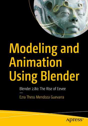
Curve and Surface
Curve and Surface are active in Object mode and Edit mode. Both are expressed in mathematical functions, and if you know Illustrator and Photoshop well, it works is the same as paths. They are defined by control points.
Example of Curves and Surfaces
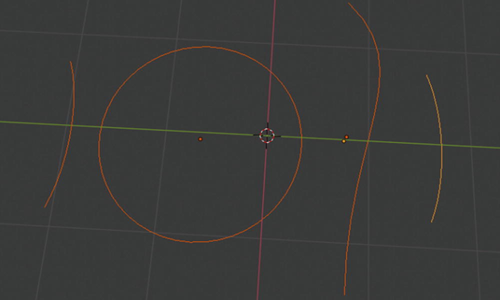
Metaball
Metaball is active in Object mode and Edit mode. Metaballs are not defined by vertices (unlike meshes), and they are not defined by control points (unlike curves and surfaces). Meta objects are literally mathematical formulas that are calculated on the fly by Blender.
Example of Metaballs
Be careful with metaballs. When they get close to or interact with each other, they tend to blend or merge.
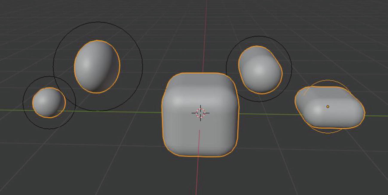
Text
Text creates text objects. It is active in Object mode and Edit mode.
Grease Pencil
Grease Pencil is active in Object mode, Edit mode, Sculpt mode, Draw mode, and Weight Paint mode. Blender objects allow you to draw in a 3D space. This acts as a container of strokes that you can create using drawing tools in Draw mode.
Example of the Grease Pencil
Armature
Armature is active in Object mode, Edit mode, and Pose mode. It is designed to be posed in a static or an animated scene; they have a specific state called rest position .
Armature
Lattice
Lattice is active in Object mode and Edit mode. It consists of a three-dimensional non-renderable grid of vertices and its main use is to apply a deformation to the object it controls with a Lattice modifier. The lattice should be scaled and moved to fit around your object in Object mode. Any scaling applied in Edit mode results in object deforming. It should also be noted that if the object is parented with Lattice deform, a Lattice modifier is automatically applied.
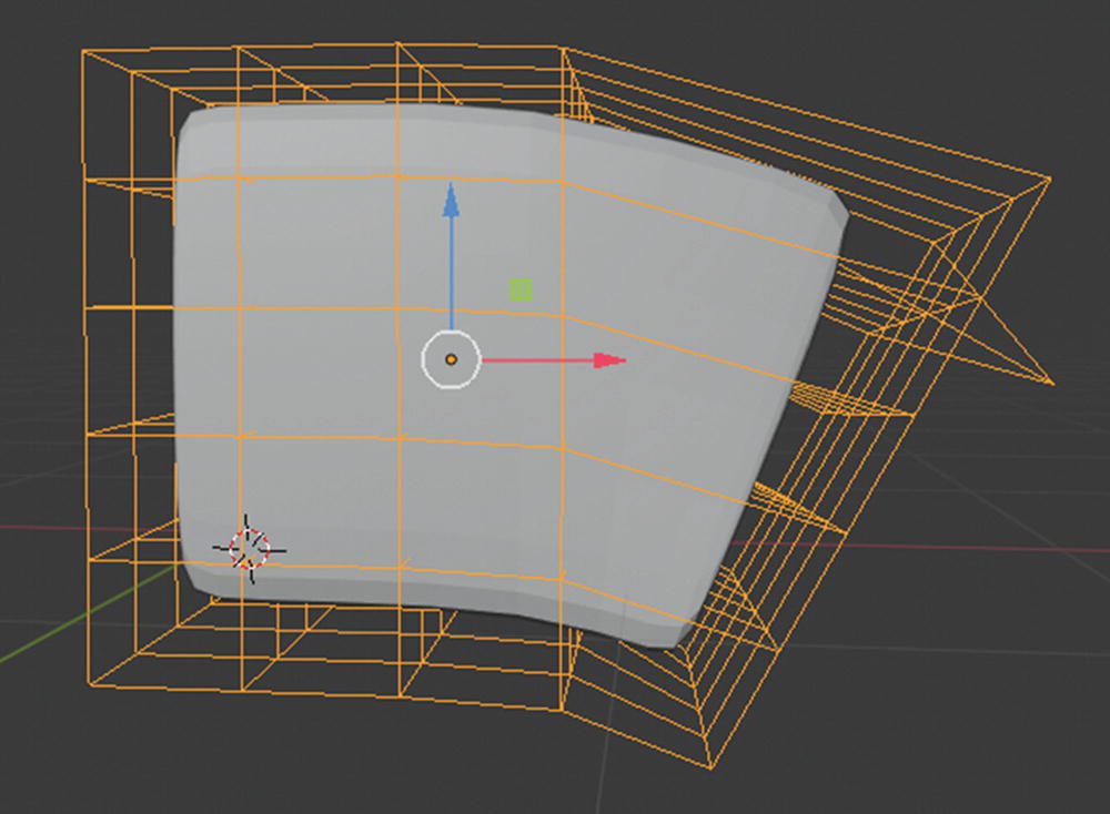
Lattice at work
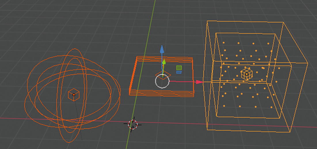
Empty
Object mode is the only active mode. Empty is a single coordinate point with no additional geometry. Because Empty has no volume and surface, it can be rendered or used for other purposes.

Empties
Image
Image is only in Object mode. It is usually used if you want to use an image as a reference.
Light
Light is only Object mode. It defines the light settings.
Lights
Light Probe
Only Object mode. It is used by Eevee as a support object. It records lighting information locally to light the scene using indirect lighting.
Camera and Speaker
Both only have Object mode. Camera is an object that provides a means of rendering images from Blender while Speaker provides sound in the 3D Viewport.
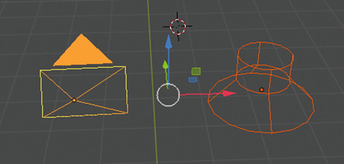
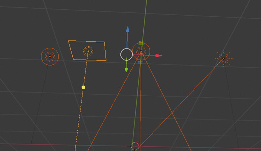
Camera at the left, Speaker at the right
Force Field
Object mode and Edit mode are the once active. It offers a way to influence a simulation; for example, to add extra movement. Force fields automatically affect everything.

Note
If you become confused by my listing objects that you can use to create your scene, there is a thin difference between a mesh and an object. A mesh is a surface defined by vertices, edges, and faces. Objects are more complex. They can be meshes, cameras, lights, light probes, and so forth. A mesh cannot become an object.
There are a lot of objects here. I discuss it soon, but let’s proceed to the menus.
Menus
Header menus: Located at the start of the header, they configure the editor and access tools.
Collapsing menus: Helpful for gaining extra horizontal space in the header.
Select menus: Lets you choose between a set of options.
Pop-over menus: Overlay menus; includes the down arrow on the right side of menu button.
Context menus: Pop-ups opened using right-click mouse button.
Special menus: Contains a context-sensitive list of operators. It is opened by a button with a down arrow on dark background.
Pie menus: Items are spread radially around the mouse.
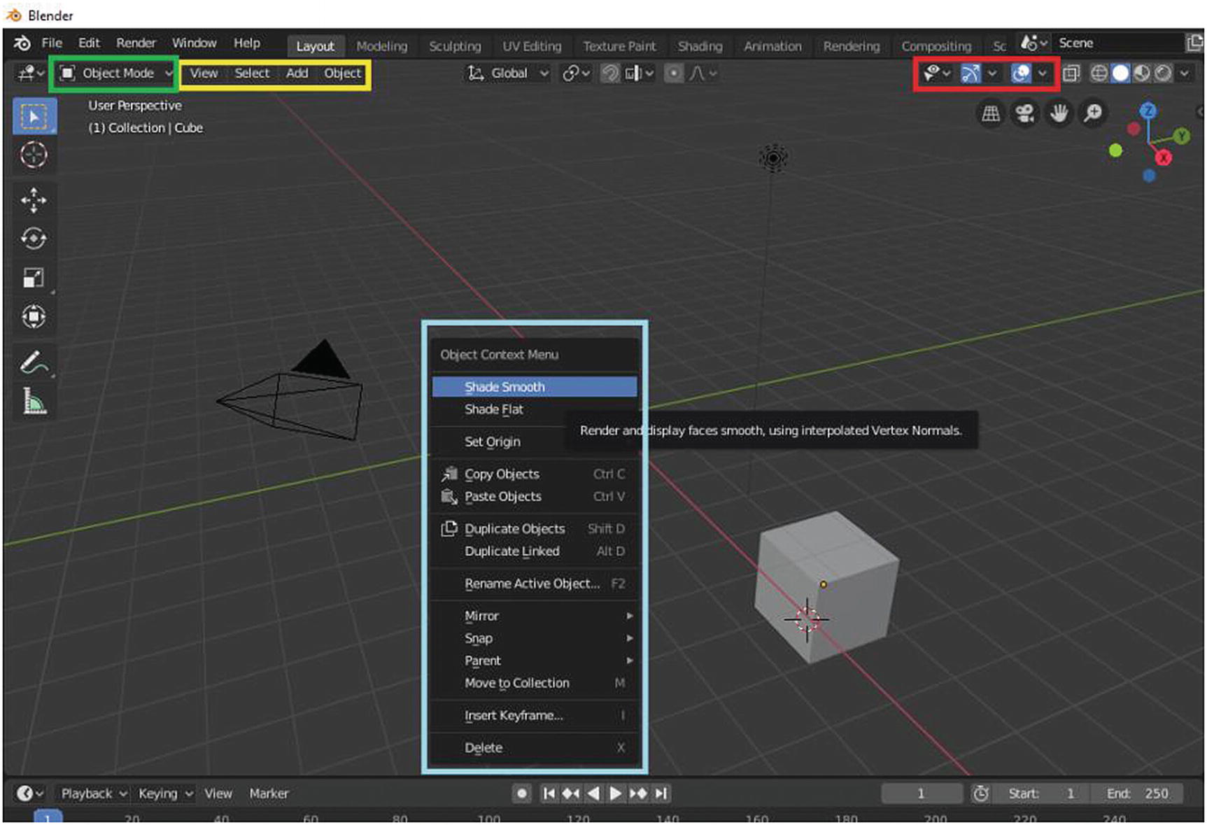
Select menu (green), Header menus (yellow), Special menus (red), Context menu (light blue)
The Mode selection under the File, Edit, and Render Header menus is called a Select menu. The Context menu that you can see in the middle of Figure 2-15 only shows when you right-click the space on your screen, but you can only do this if your mouse preference is set to left-click and you didn’t change it to right-click.
View, Select, Add, and Object are examples of Header menus while the one inside the red rectangle which is under the Compositing tab are the examples of Special menus.
Collapse menu and pop-over menu
So, let’s discuss each tools of the most commonly used workspace.
The Layout Workspace
The Layout workspace shows after the splash screen by default. This workspace contains a 3D Viewport editor in the top-left corner, Outliner in the top-right corner, Properties in the bottom-right corner, and the Timeline editor in the bottom-left corner.

Layout workspace
Inside the brown rectangle is the 3D Viewport. The one inside the red rectangle is the Timeline Editor, the one in the yellow square is the Outliner, and the one in the green rectangle is the Properties.
The 3D Viewport
The 3D Viewport allows you to interact with a 3D scene for a variety of purposes, such as modeling, animating, texturing, painting, and so forth.
3D Viewport has three regions: Header, Toolbar, and Sidebar.
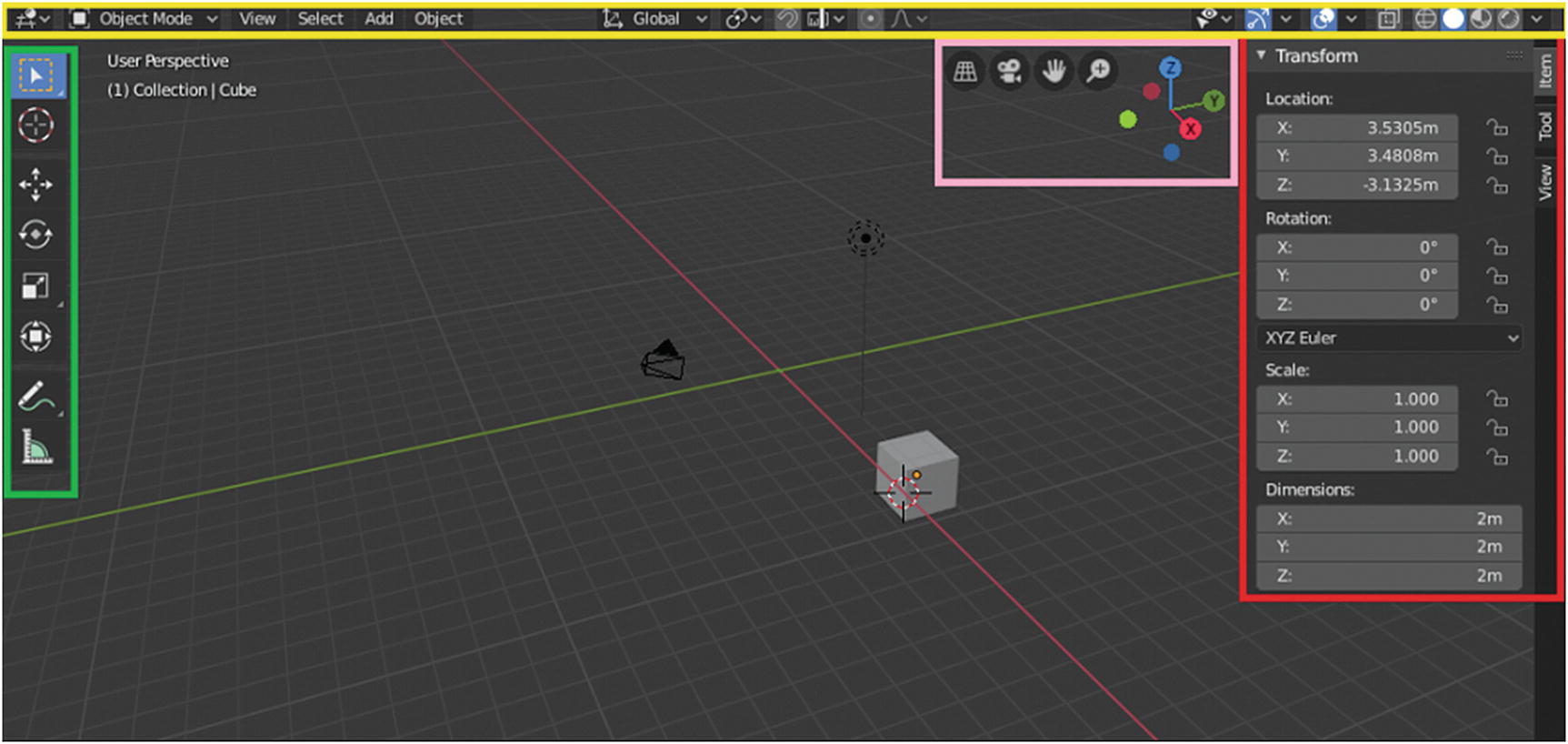
3D Viewportlayout: Header (yellow), Gizmos (pink), Sidebar (red) and Toolbar (green)
Header is also divided into three types: Mode and menus, Transform Control and Display and Shading. Gizmos are part of the Display and Shading. First, let’s discuss the modes and menus.
3D Viewport ➤ Mode and Menus
- Mesh
Object mode: View, Select, Add, Object
Edit mode: View, Select, Add, Mesh, Vertex, Edge, Face, UV
Sculpt mode: View, Sculpt, Brush, Hide/Mask
Vertex Paint: View, Paint, Brush
Weight Paint: View, Weights, Brush
Texture Paint: View, Brush
- Curves
Object mode: View, Select, Add, Object
Edit mode: View, Select, Add, Curve, Control Points, Segments
- Surface
Object mode: View, Select, Add, Object
Edit mode: View, Select, Add, Surface, Control Points, Segments
- Metaballs
Object mode: View, Select, Add, Object
Edit mode: View, Select, Add, Metaball
- Text
Object mode: View, Select, Add, Object
Edit mode: View, Edit, Font
- Grease Pencil
Object mode: View, Select, Add, Object
Edit mode: View, Select, Strokes
Sculpt mode: View, Select
Draw mode: View, Strokes
Weight Paint: View, Weights
- Armature
Object mode: View, Select, Add, Object
Edit mode: View, Select, Add, Armature
Pose mode: View, Select, Pose
- Lattice
Object mode: View, Select, Add, Object
Edit mode: View, Select, Lattice
- Empty, Light, Light Probes, Camera, Speaker, and Force Field
Object mode: View, Select, Add, Object
As you can see on the list, when it comes to Object mode, they have the same menus but it changes when it comes to the other modes, which by the name of the menu, you already have an idea about the tools. Let’s first discuss the four common menus in Object mode: View, Select, Add, and Object.
What you see in these four menus are the same in whatever objects you are in; the exception is that when you currently select Metaball, Text, Lattice, Empty, Light, Light Probe, Camera, Speaker, or Force Field, the Join under Object Header menu is disabled.
Note
Shortcut keys are also indicated at the right side of the name of the command in the menus.
View Menu
The View menu is available at all six modes of 3D View editor with the same set of commands. By default, the toolbar is enabled while the sidebar and tool settings are disabled.

Toolbar (yellow), Tool setting (violet), Sidebar (red)
What you see in toolbar depends on the mode and workspace. The Object mode in the Layout workspace includes Select, Cursor, Move, Rotate, Scale, Transform, Annotate, and Measure. There is a rectangle on the side of Select, Scale, and Annotate. It is a pop-up menu for tools. This indicates more options for the tool. I discuss this more soon. For now, let’s focus on the commands that we can see in the menus.
Set a new selection
Extend an existing selection
Subtract an existing selection
Invert an existing selection
Intersect an existing selection
Let’s discuss the Sidebar region, which consists of panels. For 3D Viewport, the sidebar consists of three panels. For now, let’s discuss some of the commands under the View menu.
Adjust Last Operation at work
Frame Selected (Numpad.) and Frame All (Numpad Home key) are for zooming in on an object. If you select one or two objects, use Frame Selected. If you want to zoom in all objects in the scene, use Frame all.
Local view (Numpad /) is to view a selected object in isolation mode. It is more effective if you have a lot of objects in the scene and you only need to modify one or two objects in it.
Cameras (Numpad 0) activates your camera in View mode.
Viewpoint is where you can set the different views for your project. You can have it in Top view (Numpad 7), Bottom view (Ctrl+Numpad 7), Front (Numpad 1), Back (Ctrl+Numpad 1), Right (Numpad 3), and Left (Ctrl+Numpad 3).
Navigation includes Orbit Left (Numpad 4), Orbit Right (Numpad 6), Orbit Up (Numpad 8), Orbit Down (Numpad 2), Orbit Opposite (Numpad 9), Roll Left (Shift+Numpad 4), Roll Right (Shift+Numpad 6), Pan Left (Ctrl+Numpad 4), Pan Right (Ctrl+Numpad 6), Pan Up (Ctrl+Numpad 8), Pan Down (Ctrl+Numpad 2), Zoom In (Numpad +), Zoom Out (Numpad -), Zoom Border (Shift+B), Zoom Camera 1:1, Fly Navigation, and Walk Navigation.
Under Navigation is Align View, where you can set the alignment of your view.
View Regions is where you can set which part of your scene is only rendered or viewed.
Play Animation is where you can render an image exactly as shown in the 3D Viewport.
Viewport Render Animation is covered in Chapter 5, where I discuss play animation and viewport render animation.
In Area, you can choose how to work in your workspace. There are six options: Toggle Quad View (Ctrl+Alt+Q), Horizontal split, Vertical split, Duplicate Area into New Window, Toggle Maximize Area (Ctrl+spacebar), and Toggle Full Screen (Ctrl+Alt+spacebar).
Select Menu
Let’s talk about the Select menu. For the Mesh object, the Select menu is quite different when in Object mode and when in Edit mode. It also depends on the object that is currently selected.
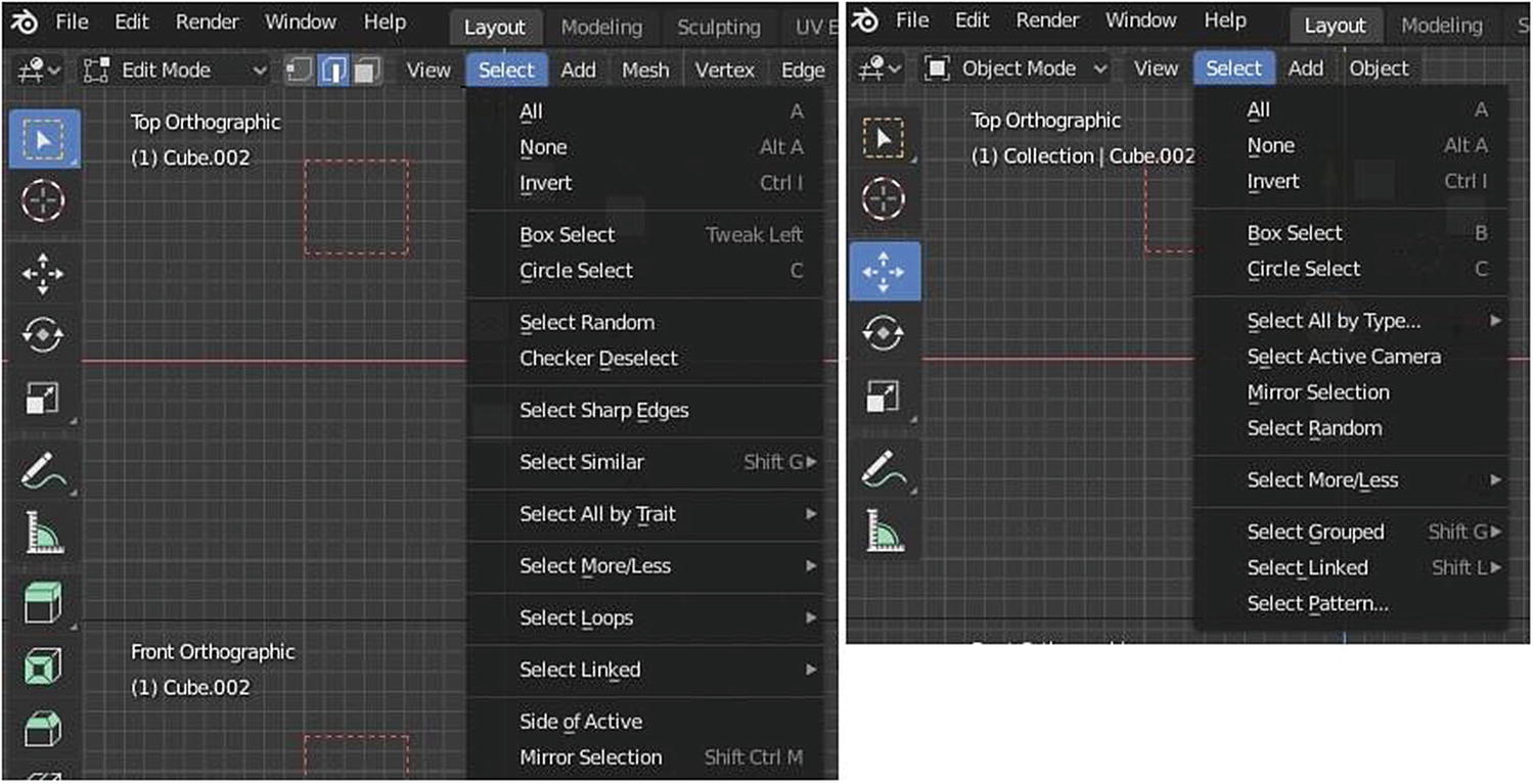
Select menu, Edit mode and Object mode
As you can see in Figure 2-22, if you want to select all of the objects in the scene, you need to click A on your keyboard and Alt+A to disable the selection. Press Ctrl+I if you want to invert the selection that currently have. It is easier than going to the Select menu. All are working in Object mode and in Edit mode.

Checker Deselect at work
Let’s talk about Object mode. Select All by Type is where you can select objects base on what type it is. This is useful if you have a lot of different kind of objects in the scene. This kind of tool is helpful in large productions.
Let’s talk about the Select menu for other objects.
The common tools under the Select menu in Edit mode under all objects are All (A), None (Alt+A), Invert (Ctrl+I), Box Select (Tweak Left) and Circle Select (C). Let’s discuss what the other tools in the Select menu of each object.
Mirror (Shift+Ctrl+M) mirrors the bone selection.
More (Ctrl+Numpad +) selects the bones connected to the initial selection.
Less (Ctrl+Numpad -) deselects the bones at the boundary of each selection region.
Parent ([ ) and Child ( ]) select a bone’s immediate parent/children.
Extend Parent (Shift+[) and Extend Child (Shift+]) select the selected bone’s immediate parent/children.
Similar (Shift+G) selects bones by property type.
Select Pattern selects objects matching a naming pattern.
Select Mirror selects mirrored lattice points.
Select Random randomly selects UVW (UV Unwarp) control points.
Select More selects a vertex directly linked to selected ones.
Select Less deselects vertices at the boundary of each selection region.
Ungrouped Verts selects vertices without a group.
Select Random randomly selects metaelements.
Similar selects similar metaballs by property types.
Select Random randomly selects some control points,
Checker Deselect deselects every other vertex,
Select Linked (Ctrl+L) selects all control points linked to the current selection.
Select Similar (Shift+G) selects similar curve points by property type.
(De)Select First/Last deselects or selects first/last of visible part of each NURBS.
Select Next/Previous selects points following/preceding the selected ones along the curves.
Select More (Ctrl+Numpad +) selects control points directly linked to the selected ones.
Select Less (Ctrl+Numpad -) reduces current selection by deselecting boundary elements.
The Select menu under Surface object has Select Random, Checker Deselect, Select Linked, Select Similar, Select More, and Select Less, which are the same as Curve. Let’s discuss Select Control Point Row (Shift+R), which selects a row of control points including active one.
Linked (L) selects all points in same strokes as the selected points.
Alternated (Shift+L) selects alternative points in same strokes as the selected strokes.
Grouped (Shift+G) selects all strokes with similar characteristics.
Select First/Select Last selects first/last point in Grease Pencil.
Select More/Less (Ctrl+Numpad+/Ctrl+Numpad -) grow/shrinks sets of selected Grease Pencil points.
Note
Camera, Speaker, Empty, Force Field, and Light Probe only have the Select menu (see Figure 2-22).
Add Menu
The Add menu has different options for different modes at the same time for different objects where it is available.
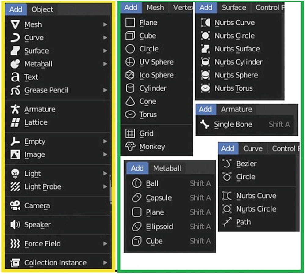
Add menu in Object mode (left) Add menu in Edit mode (center and right)
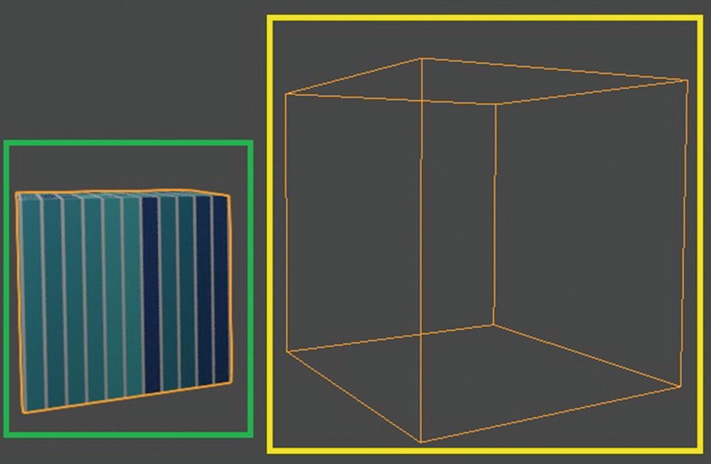
Mesh box (left) and Texture Space (right)
The Mesh, Vertex, Edge, Face, and UV header menus are in Edit mode under the Mesh object. Most of them are straightforward; the Blender docs explain anything that you are unsure about.
The most noteworthy options are under Transform Move Texture Space and Scale Texture Space, which move/scale texture space.
Figure 2-25 shows texture space.
Texture space is the space that holds or controls your texture. By default, it is attached in the object, like skin to a body. Be careful scaling or moving this because it affects the output of your texture in your mesh or any objects applied by textures.
Most of the tools under the Mesh, Edge, Vertex, and Face menus are on the Modeling workspace toolbar. The one under the UV menu is on the UV toolbar for the UV workspace.
Object Menu
The last menu that I discuss is the Object menu. It is in the Object mode for all types of objects and consists of tools that are used for manipulating objects. You can take it as a long way of manipulating objects since we already have toolbars.
There are other header menus that I didn’t discuss, but their commands are advanced. Let’s discuss Transform Controls, which are part of the Header region.
3D Viewport ➤ Transform Controls
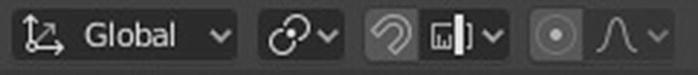
Transform Control tools
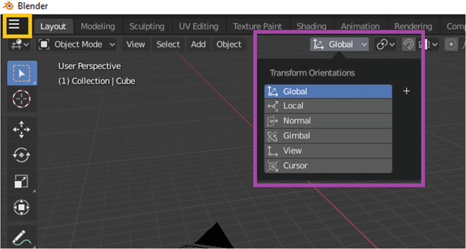
At the left are the pop-over menus for Transform Orientation, Pivot Point, Snapping, and Proportional Edit.
Transform Orientation affects the behavior of the transformations: Locate, Rotate, and Scale. The effect is seen on object manipulators, as well as on transformation constraints, Axis Locking.
Global bases the transformation on the world axis. Local bases the transformation on the object selected. When you choose Normal, the transformation matches the normal of the object selected. For beginners, normal is a direction or line that is perpendicular to something—typically, a triangle or a surface, but it can also be relative to a line, a tangent line for a point on a curve, or a tangent plane for a point on a surface.

Example of normals in meshes
Now, let’s go back to the Transform Orientations. Gimbal uses the Gimbal behavior that changes depending on the current rotation mode. Gimbal is a pivoted support that allows the rotation of an object about a single axis.
View matches its transformation of the 3D Viewport.
With the Cursor, the transformation matches the current defined 3D cursor in the Blender.
The Pivot Point tool allows you to choose the location of the origin point. Depending on your project, changing the location of the pivot point or the origin point helps you easily manipulate your objects.
The Snapping tool gives you the ability to snap objects and meshes to various types of scene elements during a transformation. Increment snaps to grid points, and when you are in orthographic view, the snapping increment changes depending on zoom level. Vertex snaps to vertices of mesh objects. Edge snaps the edge of a mesh object. Face snaps the face of a mesh objects. Volume snaps to regions within the volume of the first object found below the mouse cursor. This one controls the depth of the transformed element.
The last thing I’d like to discuss in 3D Viewport is the Proportional Editing tool, which transforms selected elements (such as vertices) and nearby elements. For example, the movement of a single vertex causes the movement of unselected vertices within a given range. Since proportional editing affects the nearby geometry, it is very useful when you need to smoothly deform the surface of a dense mesh. This tool is typically used in Edit mode but it can also be used in Object mode.
You can see that there are two additional options in the Proportional Editing tool in Edit mode, which are Connected Only and Projected from View. When you use Connected Only, the proportional falloff spreads via geometry rather than using a radius only. This means that you can proportionally edit the vertices in a finger of a hand without affecting the other fingers. While the other vertices are physically close in 3D space, they are far away following the topological edge connections of the mesh. If you use Projected From View, the depth along the view is ignored when applying the radius.
Let’s now discuss the Display and Shading part of the Header region.
3D Viewport ➤ Display and Shading
These tools affect how you can see your object or scene in the viewport. These set of tools consists of Object Type Visibility, Viewport Gizmos, X-Ray, Viewport Overlays, and Viewport Shading.
Display and Shading tools
In the Object Type Visibility pop-over menu, the visibility and selectability per type of object can be specified or limited per 3D Viewport. The eye icon beside each object types limits the visibility while the arrow icon limits the selectability. This tool is more efficient for a large production where you have many objects to manipulate.
Gizmos at work
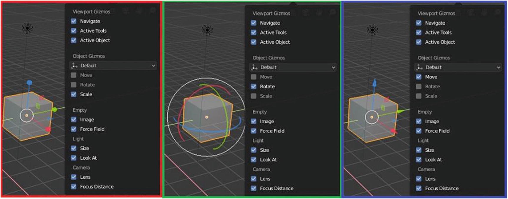
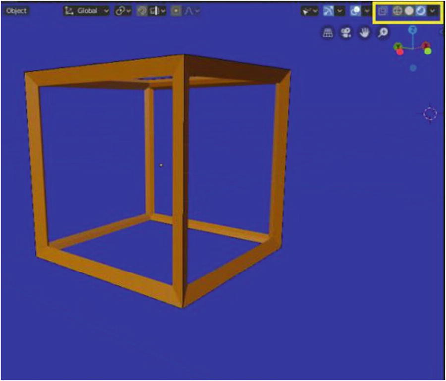
Next is Gizmos . This pop-up menu helps you easily manipulate the settings for some of your tools. It is a bounding box used for manipulating 3D objects. What you can see in this pop-up menu is more on enabling/disabling the basic tools in the 3D Viewport, like move, rotate and scale. When you do move, rotate, and scale an object, there is an arrow pointing the x, y, and z axis, as shown in Figure 2-29. By default, they are disabled, but you can move the object by using a hotkey like Rotate, which is R, or Scale, which is S, or move, which is G, and press the axis letter so that it transforms consistently to the axis you want. For example, if you want to move along the x axis, press G, and then X; the movement is activated only along the x axis.
As you can see in Figure 2-29, when you enable the scale under Object Gizmos, there are three arrows showing in the cube pointing toward different direction. One to the x axis, one to the y axis, the other one is to the z axis. This is the same when you enable the move function except that there is difference in the tip of the arrow. In scale, the tip of the arrow is in square while in the move the tip of the arrow is in cube. When you enable rotate, a half-circle indicates a turn in direction. This is how Object Gizmos work, but we also have Viewport Gizmos. What are they and how do they work?
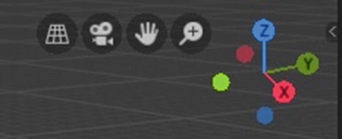
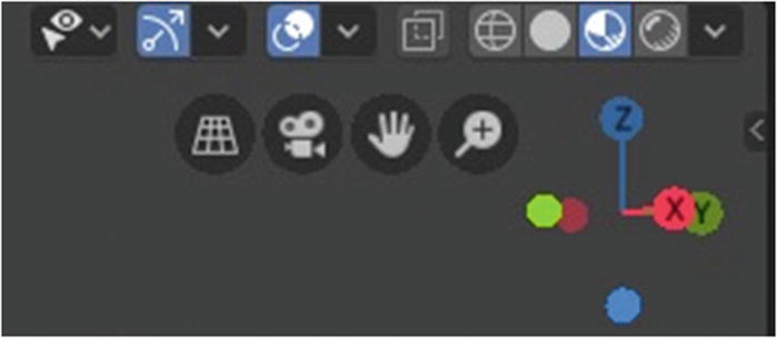
Viewport Gizmos: Navigate
The one shown in Figure 2-30 is the Gizmos for Navigation. This feature helps you to easily navigate in the viewport, especially for laptop users (like me) or beginners still learning the hotkeys to navigate the 3D Viewport. I can say that this new feature is quite helpful.
Let’s talk about Viewport Overlays. This pop-over menu is also for disabling/enabling tools regarding things for modeling like
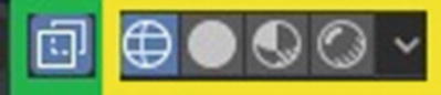
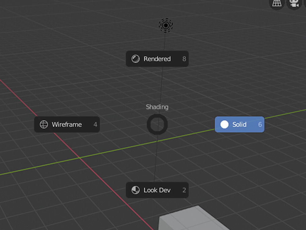
Left to right: Show X-Ray, Viewport Shading, Wireframe, Solid, LookDev, Rendered

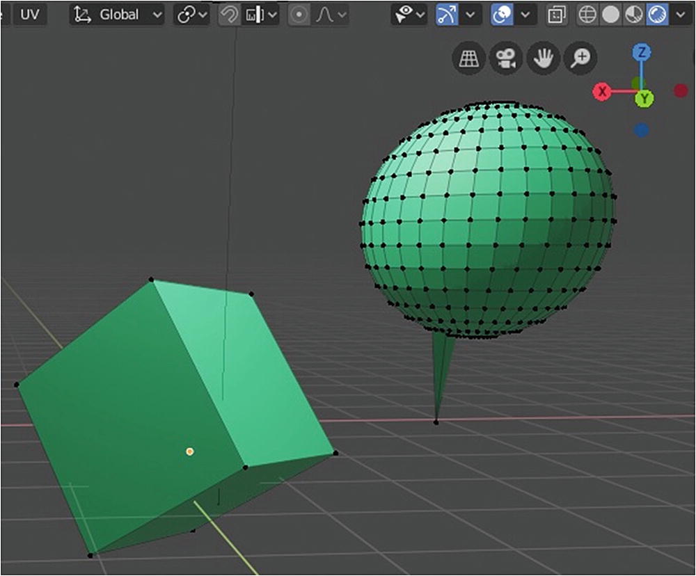
Viewport Shading: Show X-Ray plus Wireframe in Edit mode (left) and Viewport Shading: Wireframe only in Edit mode
In Figure 2-32, the difference when you use the Show X-Ray or Transparency tool. Where Show X-Ray is active, you can see the other side of the sphere and cube. On the right side, you can only see the side of the object facing the screen. This feature can help you easily select vertices, edges or faces without accidentally selecting the vertices, edges or faces from the other side of an object.

Viewport Shading: Wireframe mode setting
Let’s talk about Color. When you choose single, the scene color was based to a single color only. When you choose object, it shows the object color and when you choose random, it randomly chooses a color.
Let’s talk about Background. When you choose Theme, what you set in the User Preference is used in the background. When you choose World, whatever the setting is in the World scene is used as the background. Take note that the world scene has its own lighting so be careful on the color you choose for this part. You also better check its setting before applying this as your background. When you choose viewport, whatever settings you have for the viewport are the ones to use.
Let’s talk about X-Ray. We know in laboratory tests X-rays show what’s inside of a body. It’s the same for this feature. When you adjust the X-Ray value to a higher value, the more you can see what is inside of an object.
Let’s talk about Outline. The outline means the sides of the object. You can change it to the color you want to emphasize the sides of the objects. You can also use this to know the silhouette of the 3D model you are making, if it matches the idea you have in mind.
MatCap usually used for sculpting for you to clearly see the shadows of your meshes and this kind of lighting use a material capture to light the objects in the scene.
Flat does not calculate any lighting, which is why Figure 2-42 is too bright and there are no shadows.
In Studio, a shadow isn’t that visible unlike in MatCap. This kind of setting use studio lights to light objects and this kind of lights can follow camera or be fixed.

Studio, MatCap, and Flat at work
We can see in Figure 2-34 the differences of the three lightings. In Flat, it was too bright. You can’t see any shadows at all while in Studio, shadow isn’t that visible unlike in MatCap. But since this can only be seen in view mode and is not seen in the actual render of an image, this might help you in some way.
Before I proceed to the next shading mode, I’d like to briefly discuss this Backface Culling. What is Backface Culling? Backface Culling is an important part of how a 3D software or engine determines whether a polygon of a graphical object is visible. It is a step in a graphical pipeline that tests whether the points in the polygon appear in counter-clockwise or clockwise order when projected in the screen. If not visible, the polygon is culled from rendering process, which increases efficiency by reducing the number of polygons that the hardware has to draw.

Viewport Shading: LookDev mode
Viewport Shading: Render mode
In the LookDev settings, there are two options for lighting: the Scene Lights and Scene World. When you activate the Scene Light, you see how your lighting in the scenes affects your materials. The lamp you choose or sun, whatever lighting you have in your scene. If you choose Scene World, you see is the effect of the light coming from the World Scene. You can also change the direction of your lighting by changing the Rotation. This means you can also use your scene lamps or scene world lighting to test in LookDev. But that makes the process a bit slower.
Let’s now move to the last Shading display, the Render mode. In this mode, you can see what your project looks like in the final render. You can check the mesh, materials, and lighting, as you can see in Figure 2-36.
Figure 2-36 shows lighting at work and material at Render view mode. It does seem a little similar with LookDev but in LookDev, by default, scene lighting and scene world are not used for faster performance, for instant previews and more responsive editing. There are pause button that appears beside the Viewport Shading tools for you to be able to pause or cancel the rendering process.
3D Viewport ➤ Toolbar
The shortcut key for activating tools in the toolbar is spacebar + <the tool’s shortcut key>. These tools are quite helpful because not all beginners can easily adapt to software user interface and shortcuts but if they are familiar with some tools, they can at least easily get started.
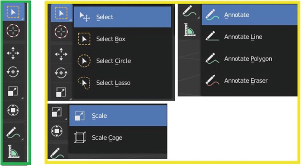
Toolbar for Layout workspace (left) and Available options for Select, Scale and Annotate (center and right)
When you look closely in Select, Scale and Annotate icons, you can see a small triangle. This indicates that there are other options for the tool. On the left side of the figure, there are the other options for the three tools.

Select Lasso tool at work
Under You Select tool is the Cursor tool (spacebar), which is used for editing for indicating the basis of the transformation that is done to objects. 3D software like Blender works through a lot of calculations and formulas. For example, in order to scale an object, the program needs to know the basis of the scale computation. As in our Geometry subject, we cannot completely solve a problem without a given variable. This is the same with the 3D software. That is the reason we have this cursor tool. Pivot Point is to let the program know the given location of the object for its transformation.
Let’s discuss the Scale tool , which also has a pop-up menu.
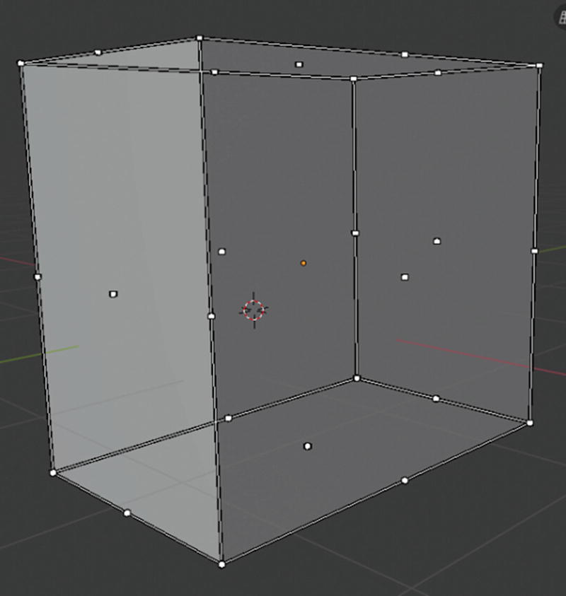
Scale Cage at work
As you can see in Figure 2-39, there are white points in the edges and corners of the mesh that is currently working on. That is the Scale Cage tool at work. You can scale the edge corner in the direction you wanted without affecting the other edge corner unlike in scale only.
The Annotate tool has four tools under it: Annotate (5) creates a simple note; Annotate Line (6) creates a note that uses a line; Annotate Polygon (7) is the same as Annotate Line but you can click the space, and it automatically creates a line while right-clicking the space to stop it; and Annotate Eraser (8) erases the annotation.
The Annotation hotkey is spacebar+D since the spacebar is the default hotkey for accessing any tools in the toolbar. But when you click the Annotate tool, the Annotate tool hotkey changes from D to 5. Changes to Annotate hotkeys affect other hotkeys, so be aware.
Under Scale tool is the Measure tool (M). This tool can measure more than lines. It also does angles by dragging up the middle portion of the line formed by the measuring tool. If you want to delete the measurement you created, you need to select it and press X in the keyboard or by clicking another tool. It also should be noted that to create new measurement, you need to tweak left anywhere, drag ruler segment to measure an angle and hold Shift while dragging to measure surface thickness.

Measure at work
3D Viewport ➤ Sidebar

Select tool activated and shown in Sidebar ➤ Tool panel
In Figure 2-41, aside from the active Select Box tool, you can see the selection modes in the Tool panel.
You can also see the current workspace in the Workspace panel. The View tab is where you adjust the camera settings and the 3D cursor settings.
The Sidebar
Before I talk about the other editors in the Layout workspace, let me talk about the Status Bar.
This bar is at the bottom of your screen. It is helpful especially when you want to know about shortcuts, the number of vertices/faces that you currently have, or the amount of memory your computer has used while working on your current project. It also gives suggestions on what to do while you’re taking an action, which can be very handy.
Outliner
Outliner is a list that organizes data in the Blend file, like scene data, video sequencer data, or anything that is stored in a Blend file. It is used to view the data in a scene, select and deselect objects, hide or show an object, enable or disable the selection, enable or disable rendering or an object, delete objects, or unlink data.

Outliner
Figure 2-42 shows the active objects. You can filter the objects and the arrangement of your objects through the settings under the funnel icon; but that setting is only available in Outliner, in Layout workspace. You can also create new collection by clicking the shoebox-like icon with a plus beside the filter setting.
Let’s now proceed to the Properties Editor.
Properties
Properties (Top Left ➤ Right: Armature, Curve, Mesh, Lattice; Bottom Left ➤ Right: Metaball, Surface, Grease Pencil and Text)
What you can see in the Active tool and Workbench settings in the properties is the same as what you can see in the tool panel of Sidebar. It displays the current active tool of the toolbar and the other settings related to the tool.
Now, we let’s discuss the Render settings that fall under scene settings.
Render Settings
Eevee is used interactively in the 3D Viewport but also produce high-quality final renders but unlike Cycles, it is not a raytrace render engine. Instead of computing each of ray light, it uses a process called rasterization, which estimates the way light interacts with objects and materials using numerous algorithms.
Cycles is Blender’s physically-based path tracer for production rendering. It is designed to provide physically based results out-of-the-box, with artistic control and flexible shading nodes for production needs.
Workbench is optimized for fast rendering during modeling and animation preview. It is not intended to be a render engine that renders final images for a project. Its primary task is to display a scene in the 3D Viewport when it is being worked on. It is noted that even though the Workbench engine is not intended to render final images/animation, it is also among the options in Render Engine.
By default, Cycle is the render engine that is selected in the options.
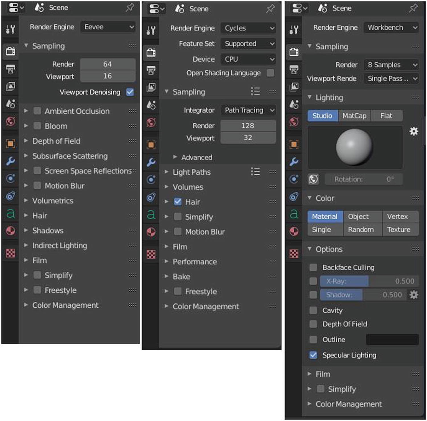
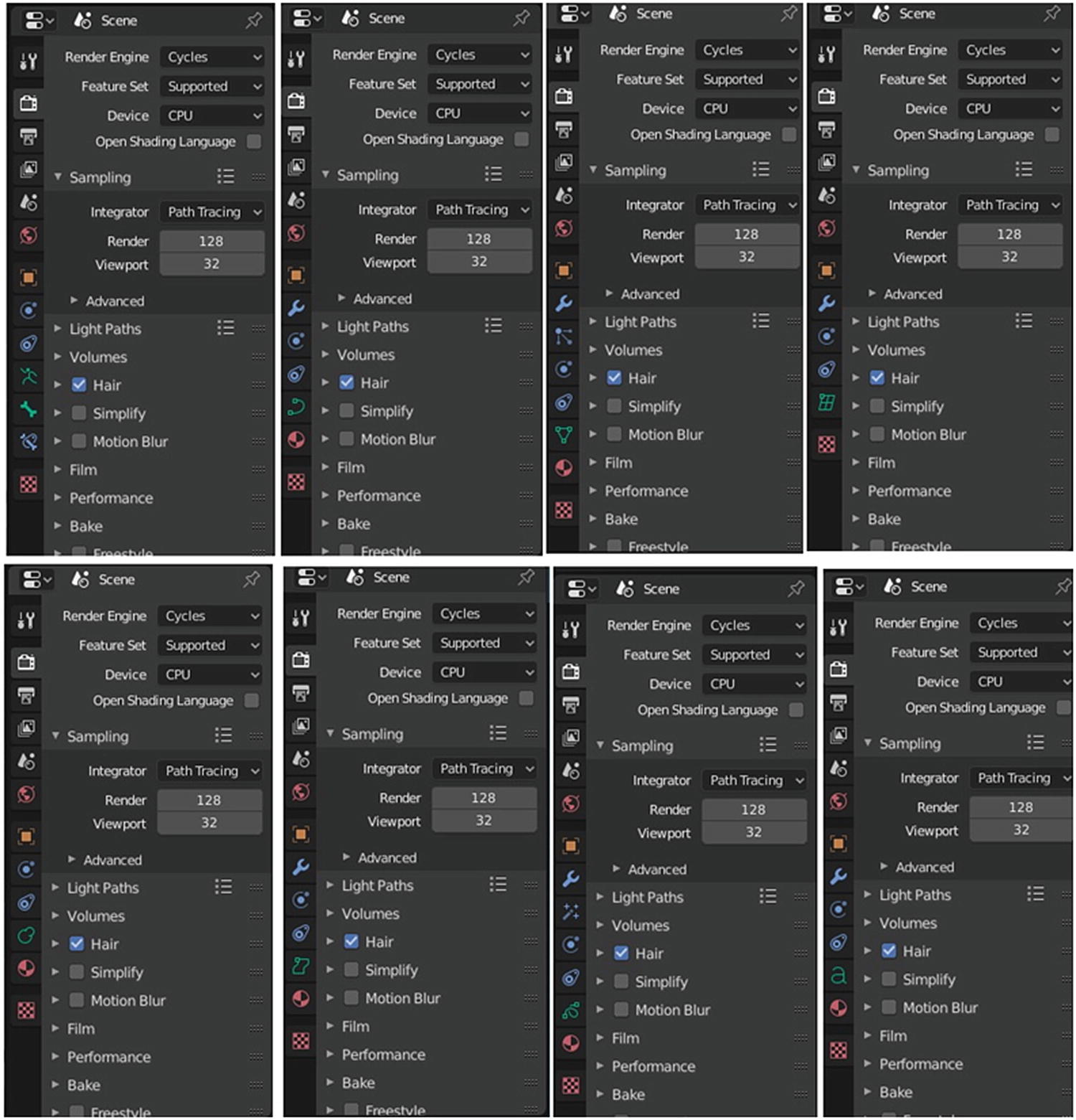
Eevee, Cycles, and Workbench: Properties ➤ Render
Eevee and Cycles both have Motion Blur, Hair, and Freestyle. The common settings for the three render engines are Sampling, Simplify, Film, and Color Management.
Sampling Settings
Ambient Occlusion is a method to approximate how bright light should be shining on any specific part of a surface, based on the light and its environment. Enabling it helps you add realism to your scene.
Bloom is a post-process effect that diffuses very bright pixels. Enabling this one helps you manage the brightness of your scene.
Depth of field is the distance between the nearest and the furthest objects that are in acceptably sharp focus in an image. This technique is used in photography.
Subsurface Scattering is a mechanism of light transport in which light that penetrates the surface of a translucent object is scattered by interacting with the material and exits the surface at a different point. Just like Ambient Occlusion, this setting can help you add realism to your scene.
Screen Space Reflection affects all materials and uses the depth buffer and the previous frame color to create more accurate reflection than reflection probes.
Motion Blur creates the blurred effect in animation.
Volumetric adds a lighting effect on your scene to allow you viewer to see beams of light shining through the environment.
Hair is used when you have hair particles in your scene to give more effect to it.
Shadows sets your scenes’ shadows to give more effect and realism.
Indirect Lighting sets your indirect lighting, like Light Probes. Here, you can bake your lighting and make additional adjustment for better view of your scene.
Film adjusts things related to transparency or pixel setting of an image.
Simplify sets the global maximum subdivision level and global child particles percentage during rendering and during its project’s process in the viewport.
Color Management adjusts the color or anything related to best display of an image or animation that is rendered.
Volumes renders effects like fire, smoke, mist, absorption in glass, and many other effects that cannot be represented by surface meshes alone.
Light Paths sets the number of light bounces.
Freestyle draws stylized strokes and sets the thickness of the strokes.
Bake manipulates the freezing and recording of the result of a computer process
You can see on the top part of the Cycles, there is this select menu for device. In Cycles, you can choose how to render your image, if you use your GPU or CPU to render it.
Note
GPU stands for graphical processing unit; it handles the visual elements. CPU stands for central processing unit, which handles the physical and logical elements of the computer.
Next, let’s discuss the Output settings.
Output Settings
Output is where you can set what file extension or where your final image is saved. You can set the final color scheme if it is RGB, RGBA, or Black and White. You can set the compression of the image too.
Stereoscopy allows the use of multiple views in the scene.
Metadata is the data of the file or image. You can set the information you want your file to have when it was saved.
Post Processing is the final processing. Adding a final effect to your image makes it look better.
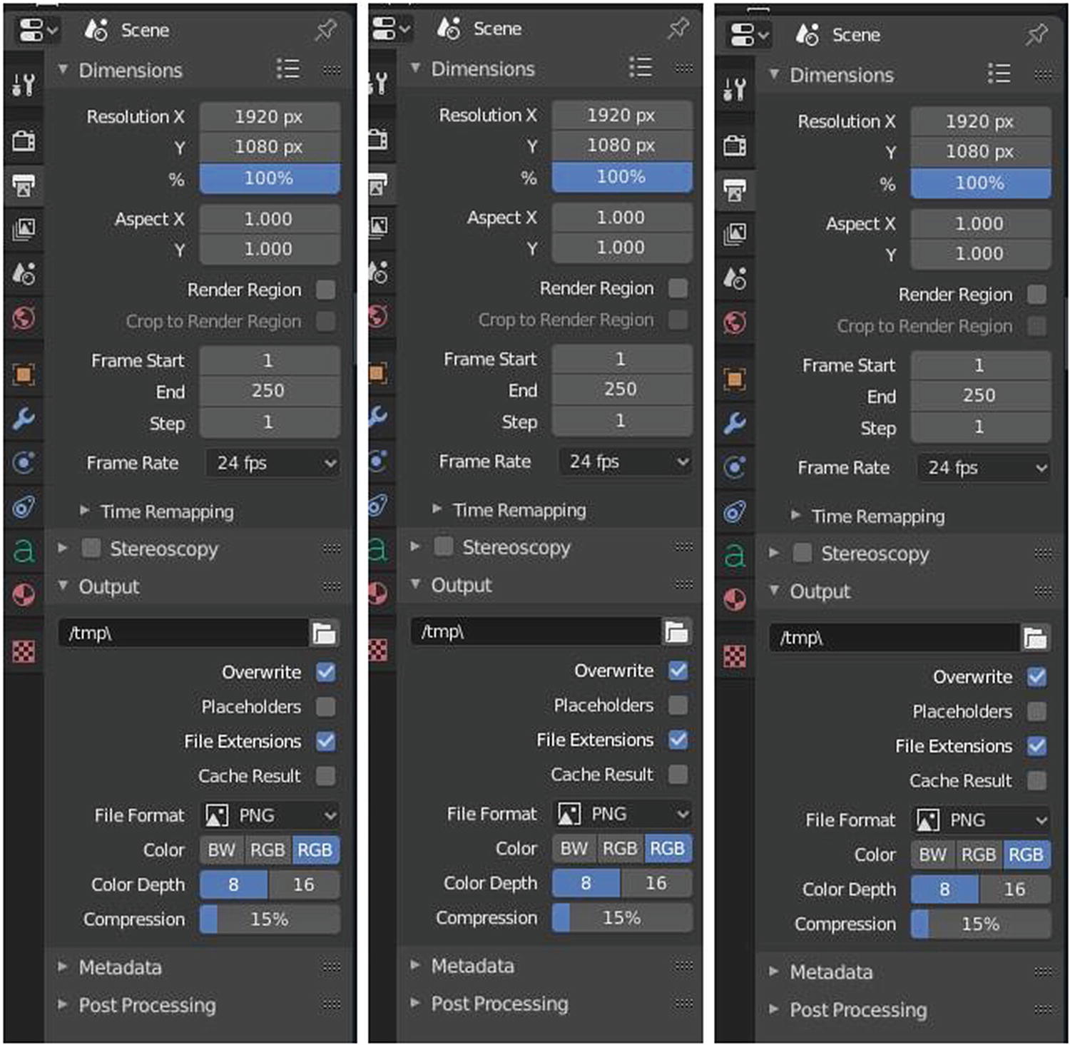
Eevee, Workbench, and Cycle: Properties ➤ Output
View Layer Settings
View Layer is commonly used for compositing or post-processing process.

Workbench (top left), Eevee (bottom left) and Cycles (right): Properties ➤ View Layer
Renders can be separated into layers. It is different from collections because collections are used for objects and layers are used for rendered images for post-processing.
View Layer can save you from having to re-render your entire image each time you change something, allowing you to instead re-render only the layer/s that you need, which is useful in animation. Adding and removing layers is done in the settings, which show the list of layers that you can see at the upper-right corner of your screen.
You can add layer by clicking the overlapping paper icon at the right. You can also delete a layer by selecting the layer first and clicking the X icon. Note that the current layer selected in this section is the layer that appears in View Layer under Properties.
Passes Settings
Combined delivers fully combined RGBA buffers.
Z delivers the Z value pass.
Mist delivers mist factor pass.
Normal delivers normal pass.
Ambient Occlusion delivers an ambient occlusion pass.
What is Passes all about? Passes split rendered images into colors, direct and indirect light to edit them individually, and extracts data such as depth or normals.
Eevee’s Passes settings include Subsurface Direct, which delivers a subsurface direct pass, and Subsurface Color, which delivers a subsurface color pass.
Cycles’ settings in Passes include Cryptomatte, which is a standard to efficiently create mattes for compositing. Unlike in Material and Object index passes, the objects to isolate are selected in compositing, and mattes are anti-aliased, and take into account effects like motion blur and transparency.
Scene Settings
Now, let’s proceed to the next category, which is Scene. All render engines have the same settings at this category.
Under the Scene panel, there is Camera, where you choose an active camera for rendering scene; Background Scene, where you set a background for your scene; and Action Movie Clip, where you set active movie clips for constraints and viewport drawing.
World Settings
The next category is World, where you can adjust everything that can affect your project. The world environment can emit light, ranging from a single solid color to arbitrary textures.
Viewport Display at work under Rendered Shading Viewport and Workbench Engine

Viewport display at work under Rendered Shading Viewport and Eevee (red) and Cycles (blue)
The Viewport shading’s color remains blue, the color of the background changes and become white which is the color indicated under the Surface panel. This means that for Eevee and Cycles, Surface’s settings is based on the background color, not the viewport display.
Custom Properties is if you want to edit a property and this is quite too technical.
Eevee and Cycles both have Surface and Volume. Eevee has Use Nodes settings, which you cannot see in the Surface settings in Cycles.
Use Nodes in the Surface setting of Eevee enables you to use shaders for your World settings. When you disable this, the three options below it (Surface, Color, and Strength) are hidden.
Surface consists of the list of BSDF shaders that you can use for your World setting. Color consists of some shaders (like Texture Shaders, Input Shaders, Color Shaders, and Converter Shaders) that you can use for your World settings when you click the small circle beside the color picker. You can also change the color using the color picker. Strength is where you can adjust the strength of the impact of the color or shaders in the World settings. If you click the small circle beside the input box, you can see a lot of options that can help you improve your world settings.
The settings I discuss for Surface, Color, and Strength are seen in Eevee and Cycles.
Object Settings
Object is where you can adjust the things related to an object, like its location, rotation, scaling, object relations, collections, visibility, and so forth. The three render engines have the same settings for Object except that Cycles have Motion Blur. I’d like to note that in some objects, the motion blue setting in Cycles doesn’t appear, such as when your current selected object is Light.
The Transform panel is where you can move, scale, and rotate the selected object in exact value you wanted. You can even change the flow of the rotation through Rotation mode. Delta Transform is an extra data added to the object that is transformed.
The Relations panel is where you can set the relationship between the objects. You can set which object is the parent or the basis of the transform that you will do in the scene.
The Collections panel is where you can assign your object to an existing collection or even remove it from the collection. You can even create another collection from to be part of the object that is currently selected.
Instancing helps you speed not only your modeling but also your rendering. Because what it does is duplicating your elements without duplicating the data it does have. What does it mean? Every object in the scene has its own data or properties. Duplicating the objects together with its properties make your GPU or CPU work a lot harder, ended up rendering slow. What’s instancing does is to duplicate only the object, like cloning, without taking its properties.
Motion Paths is used in animation. This setting is for paths that direct the objects on movement.
Visibility sets the visibility and includes Ray Visibility. The object can only be seen in viewport but not in the renderer and other settings related to visibility.
Viewport display helps you manipulate things related to the viewport, such as displaying the object name by enabling the Name; displaying the object’s origin and axes in the viewport by enabling Axis; making the object draw in front of other objects by enabling In front; and setting how to display the object in the viewport in Display As.
Custom Properties allows you to add and edit a property. It’s an advanced topic.
Physics Settings
The three render engines have the same Physics settings, but this setting depends on the object currently selected.
The Physics system allows you to simulate a number of different real-world physical phenomena. You can use these systems to create a variety of static and dynamic effects such as rain, smoke, dust, water, cloth, and so forth. We tackle this more in Chapter 5 since this is part of animation.
Let’s have a quick discussion about the other Properties categories.
Material Settings
Preview gives a glimpse of what your material looks like before applying it to your mesh.
Surface is where you edit your materials. There’s a slight difference between Eevee and Cycles when it comes to this. Eevee has a Use Nodes button but Cycles doesn’t. Cycles uses the BSDF list in the Select menu. Blender has its own Shader workspace.
Volume is where you edit your material to add volume to it. It has the BSDF shader list.
Surface ➤ Multiple Importance (Cycles) uses multiple importance sampling for the current material selected and disabling may reduce noise for large objects that emit little light compared to other light source.
Surface ➤ Transparent Shadows (Cycles) uses transparent shadows for the current material selected if it contains a Transparent BSDF and disabling renders faster but does not give accurate shadows.
Volume ➤ Sampling (Cycles) is where you can choose your sampling method for volume. There are three options: Multiple Importance, Distance, and Equiangular.
Volume ➤ Interpolation (Cycles) is where you can choose interpolation method use for smoke/fire volume. There are two options: Linear and Cubic.
Volume ➤ Homogeneous (Cycles) assumes the volume has the same density everywhere when using volume rendering for faster rendering process.
Note
BSDF stands for Bidirectional Scattering Distribution Function. It’s a mathematical function that determines the probability of a specific ray of light reflecting at a given angle. If the shaders have a suffix BSDF, which means that the shader scatters light. We also have BSSRDF, which stands for Bidirectional Surface Scattering Reflectance Distribution Function; it is where materials don’t simply reflect the light but absorbs it and then reflects it later.
Let’s proceed to two categories that appear in all objects: Object Constraints and Texture.
Object Constraints and Texture Settings
In Texture settings , you can create textures for your scene, such as Blend, Clouds, Distorted Noise, Magic, Marble, Musgrave, Noise, Stucci, Voronoi, and Wood. You can also choose your own image to upload as normal texture. You can also see these options in the Shading workspace. What you can do here can also be done when you are in the Shading workspace or using the Shader Editor.
Object Constraints control an object’s properties using either plain static values or another object. Even though constraints are useful in static projects, their main usage is in animation, so I discuss this more in Chapter 5.
Object Data modifies data for your object. The modifiers in the Layout workspace are a bit different from those in the Modeling workspace.
Sample Project Time!
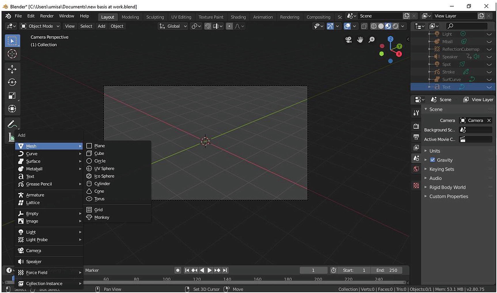
Adding object, plane
Figure 2-49 shows adding a mesh.
Press Shift+A to view the list of objects, proceed to Mesh, and choose Plane. Figure 2-49 is in camera perspective. To do that, you can go to View Menu ➤ Viewpoint ➤ Camera or press 0 on your numpad key.
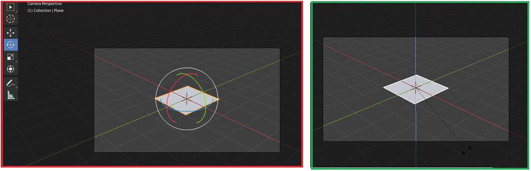
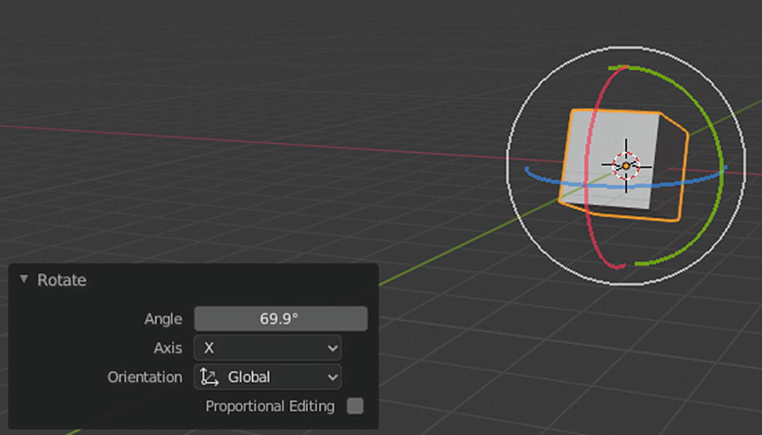
By default, plane object is lying flat on the grid of our 3D Viewport. As you click the Rotate tool, you can see three curves in green, red, and blue intersecting each other. Red means rotating in the x axis. Green means rotating in y axis and blue means rotating in z axis. There is also another technique in rotating your object. As you can see on the right side of Figure 2-50, there is a vertical blue line intersecting the plane. That is the z axis. This happens when you press R and then Z to indicate that you only rotate in the z axis. If you want to rotate in the x axis only, you can press X; press Y for the y axis.
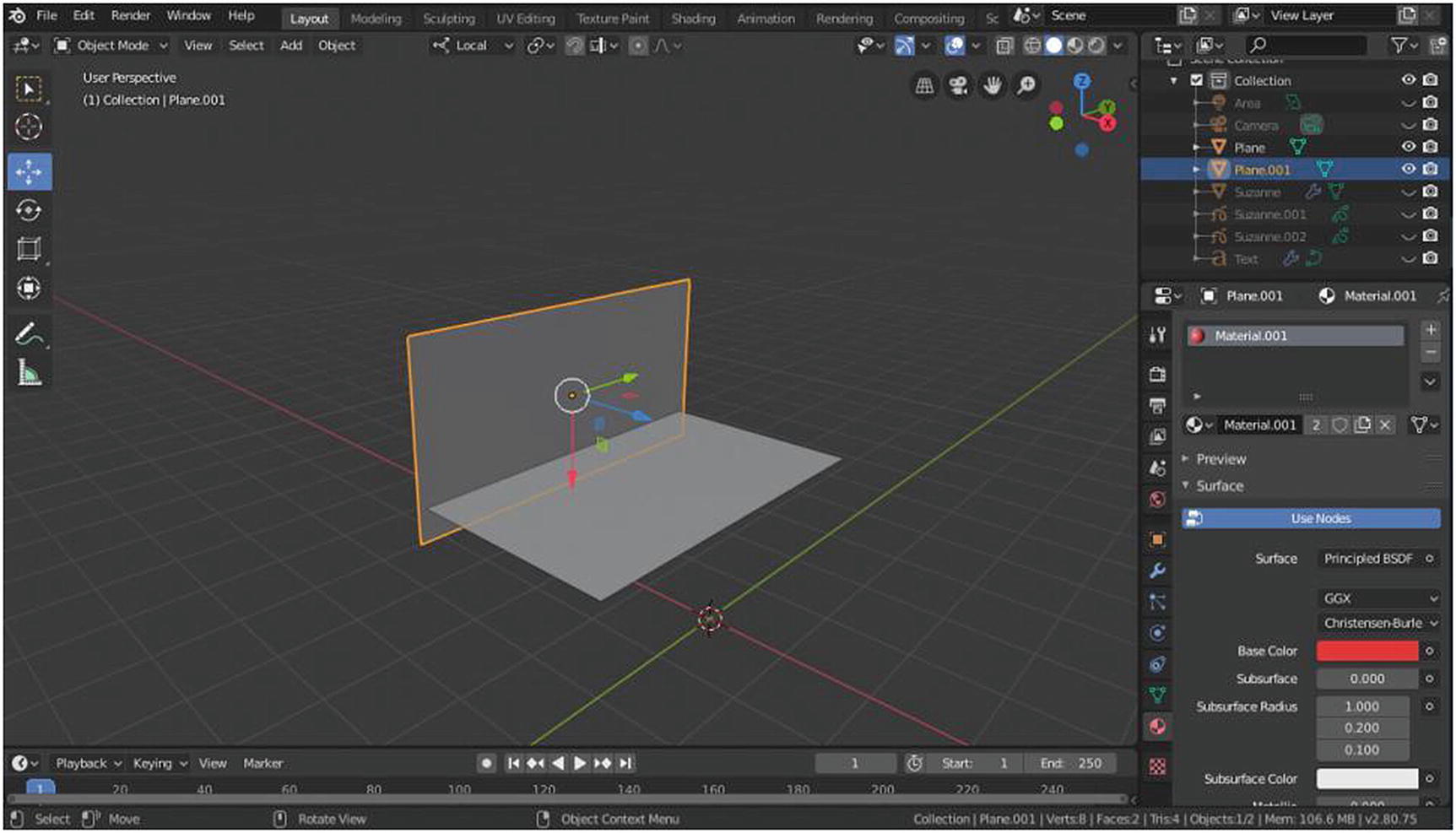
Add another plane to make a stage-like scene and add materials. Remember that you should do this in Object mode only so that you will appreciate the benefit of the Modeling workspace that we’re about to discuss.
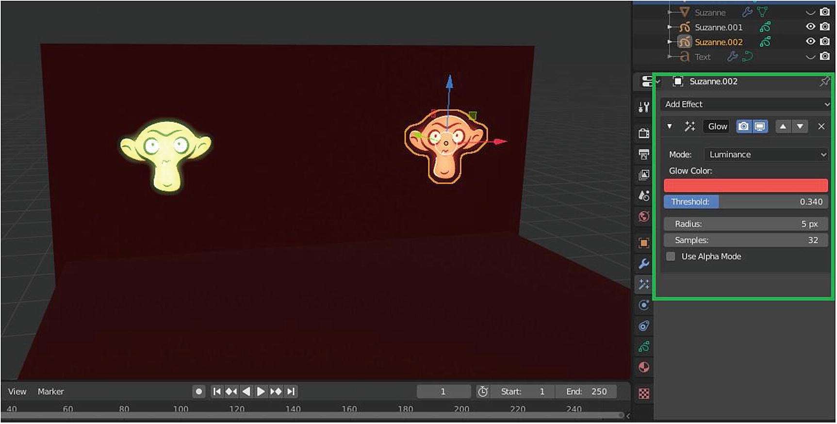
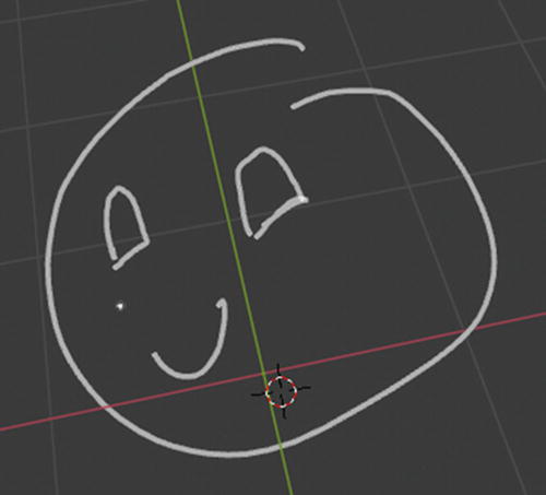
Suzanne Grease Pencil at work
Lighting is still disabled so that you can focus on the Grease Pencil. As you can see, you should add two Suzanne Grease Pencil and a glow effect in Luminance mode. The two Suzanne grease pencils should have a different glow color but they both have the following: Threshold of 0.340, Radius of 5px, and Samples of 32. By default, its radius is 50.
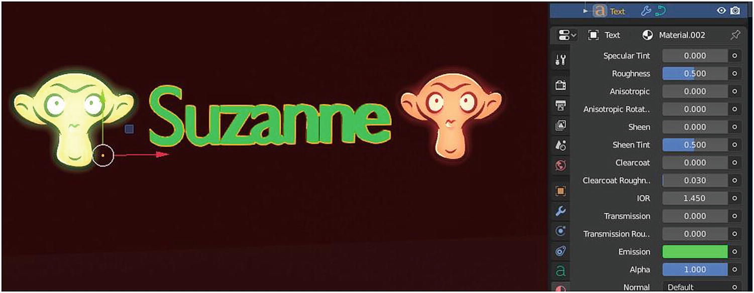
Adding materials to Text
Figure 2-53 shows adding materials to some text.
As you can see, you only use the Emission part of the Principled Shader in the Material mode for the Text. But in this way, you cannot add strength to the emission. There is also a separate Emission Shader, where you can set the strength by clicking the small circle on the surface and choose Emission Shader. Note that you should use the Eevee Render engine here.
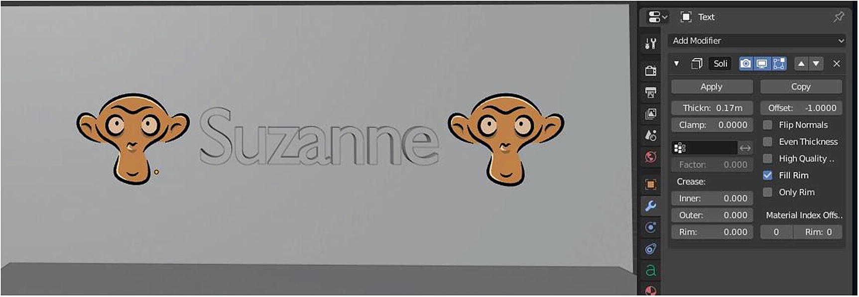
Here you add a solidify modifier for text and set its thickness to 0.17m. In the modifier, there is this camera icon and a monitor icon. Camera icon indicates that the effect of a modifier appears in the render mode/rendered image while the monitor icon indicates that the effect appears in the viewport. The up/down arrow arrange modifiers. The arrangement of modifiers affects its output. The X icon deletes the modifier. You can click the Apply button if you are satisfied with the setup of your modifier, and copy to duplicate the modifier selected.
For the area light, add a little green to the default white color and set the watts from 10w to 20w. You should also scale it out to your preferred size, which covers almost part of the stage.
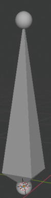
For the Suzanne mesh, you need to first go to Add menu ➤ Mesh ➤ and click Monkey to add it. Or press Shift+A, go to Mesh and click Monkey.
Now add a subsurface modifier for the Suzanne mesh and set its render to 3. The material for it is a little experiment: Base color is Gradient Texture, Subsurface Value is 0.118, Subsurface Color is 4F8CE7, Subsurface radius is 1.000/0.200/0.100, and the others are the same.
For the camera, adjust its location and rotation by using the Local under Transformation Orientation. Make sure it takes the front view of the scene.

Scene at the Layout workspace
You can see that the vertical plane has some excess. It’s better for you to create an excess because it creates an illusion of continuity in your image rather create something that is fixed on the image size you’re creating.

Final render of Suzanne
When rendering an image, you can go to Render ➤ Render Image or press F12 then a new window pops up where your image is rendered. To save the image, go to Image ➤ Save As. You could also hold Shift+S, which opens a file browser where you can select the folder to save your image in, as well the image’s file extension.
Figure 2-55 shows how I did my lighting. Figure 2-56 shows the overall effect of the lighting.
Lighting
Lighting is one of the critical parts of creating a scene even back then in traditional arts. Colors are affected by how you implement the lighting in your art. Lighting can either help you create an amazing art or destroy your art.
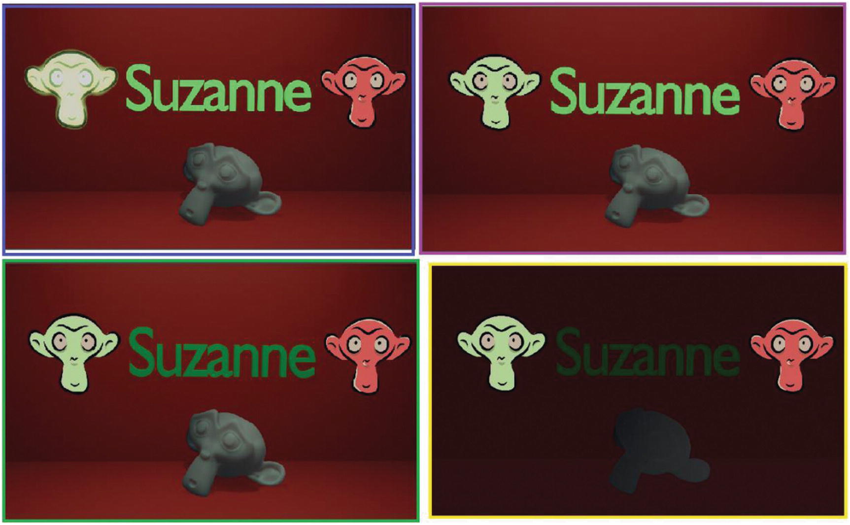
Different renders of Suzzanne
In the rendered image in the blue rectangle in Figure 2-57, there is an imbalance in the scene after I deleted the Luminance effect in one of the Grease Pencil objects. When you look at the render in the violet rectangle, the Suzanne grease pencils become ordinary.
In the green rectangle, you see how going from Emission Shader to a simple shader affects the text object and the scene. What I did with the three objects didn’t directly affect the lighting of the scene, but it did affect the appeal of the scene. Remember, it depends on how you create your lighting. It also creates the mood of your scene.
On the right, you can see the effect when I deleted the main light, which is the area light. It turns dark. It is not completely dark because of the global lighting, which is the lighting set for the entire 3D Viewport. This lighting is the color that you can set in the World category.
In the fourth render, the mesh is almost its silhouette but the Grease Pencil objects and the Text object can still be seen. This is because of the color that I used. I can say that Light and Color are closely related. In what way? There is a saying that the absence of light is black and the presence of light means white. The other colors are created due to interceptions between the two.
Did you ever face your monitor toward sunlight while working and notice differences in color, depending on the angle you are looking at? Though this happens to me by accident it is how light affects the color. It depends on the angle of the light source.

In the scene in Figure 2-58, I used is the Three-point lighting technique. Three-point lighting is a method used in visual media such as theatre, video, film, photography and in CGI. By using three light objects in separate positions, you can illuminate a scene however you desire, while controlling the shading and shadows produced by direct lighting.
Three-point lighting is composed of the following. Key light shines directly upon the subject and serves as its principal illuminator and more than anything; its strength, color, and angle is the basis of the overall design. Fill Light shines on the subject but from the side relative to the position of the Key Light and often positions at a lower place than Key Light. It balances Key Light by illuminating shaded surfaces. Not using a Fill Light at all can result in stark contrast, due to shadows, across the main object’s surface. It is usually softer and less bright than the Key light. Background or Rim Light shine on the subject from behind, often to one side or the other. It gives the subject a rim of light, serving to separate the subject from the background and highlighting contours. It creates a thin outline around the subject without necessarily hitting the front or visible surface of the subject.
Figure 2-59 shows the difference of these three lights when they act separately.
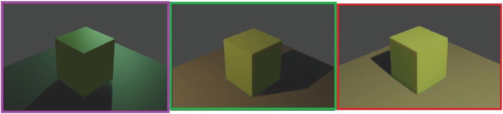
Rim Light (left), Fill Light (middle) and Key Light (right)
There is another kind of lighting technique called HDRI images . It is an easier or quicker way to light your scene. They are essentially snapshots of the real world that contain exquisitely detailed lighting information, which can transport your bland CG objects into realistic virtual environments.
An HDRI map is a panoramic photograph that covers the entire field of vision and contains a large amount of data, which emits light into the scene. HDRI stands for High Dynamic Range Image. Dynamic range is the measurement of how much brightness information is contained in an image, so a high dynamic range image is an image that has a very large range of brightness, more than you can see on your screen in one go.

HDRI image/map at work, rendered in 2.79 by yours truly
What you can really do in Layout workspace using Object mode is simple. You can add objects, lighting, and materials. Placing it in desired position and that’s it. But there’s hope, of course.