
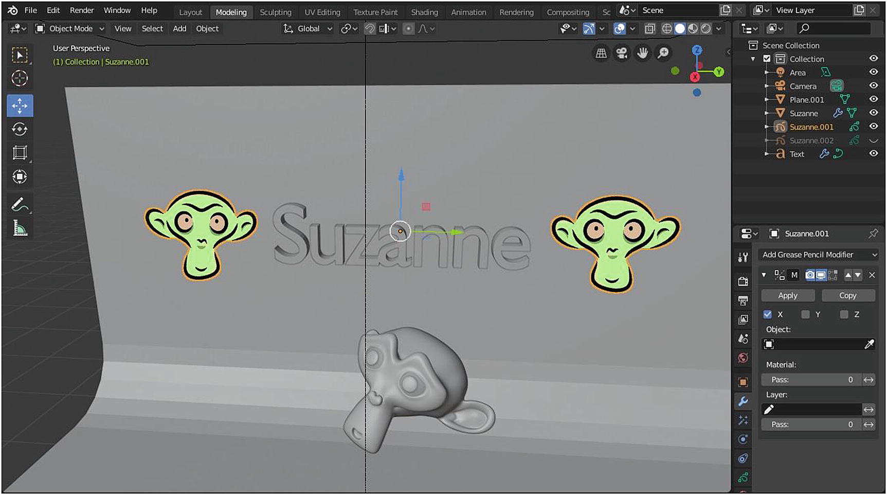
3D Viewport (blue), Outliner (green), and Properties (red)
In the Modeling workspace, there is the 3D Viewport, Outliner, and Properties. The focus of the discussion is on the Modeling toolbars.
Toolbars
What you can see in a toolbar depends on what type of object are you currently modifying.
I would like to note that objects like Camera, Empty, Force Field, Light, Light Probe, and Speaker don’t have an Edit mode. Even if they appear in the Modeling workspace, you can only manipulate their settings when you switch to Object mode.
By default, all toolbars are designed only in one column, but you can make them wider by hovering your mouse at the edge and dragging the black double-sided arrow to the right.
Some of the tools that I discussed in the Layout workspace are also carried out here: the Select tool (arrow icon), the Cursor tool (plus sign inside a circle icon), the Move tool (arrow in four directions), the Rotate tool (two arrows in a circular direction), the Scale tool (small box with small arrow pointing to larger box), the Transform tool (square with four arrows inside a circle), the Annotate tool (pencil icon), and the Measure tool (two rulers).
Since I already discussed these tools in the Layout workspace, I will focus on the tools that are present only when you are in the Modeling workspace or in Edit mode.
CONTEXT MENU
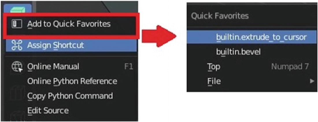
Quick Favorites
When you click the Assign Shortcut, you see a capital A pop up. When you hover your mouse in it, it changes to Press any key. This tool helps you easily apply your custom hotkeys. Above Assign Shortcut, you see Add to Quick Favorites. If you have tools that you often use, you can add it to Quick Favorites for ease of access. To access everything in your Quick Favorites, just press Q on your keyboard, and you see the menu shown on the right side of Figure 3-2. Whatever you add to Quick Favorites appears in that pop-up menu.
Below Assign Shortcut, you see Online Manual. Yes, from here, you can look at the documentation about the tool that you are using in Blender to know how it works. When you click that link, you are redirected to the Blender Manual site.
Next is Online Python Reference. If you are a developer, you might want to take a look at this one. This one redirects you to the part of the Blender Manual where the source code is documented. This is really for programmers/developers. The Copy Python tool and Edit Source are tools for programmers/developers. If you want to modify a tool, you can use these tools.
Toolbar ➤ Mesh

Tools in the toolbar for Mesh object
The leftmost menu in Figure 3-3 is the actual toolbar; what you see on the right side are the tools that appear after you click the small triangle beside the icon. Let’s start the discussion.
Since I already discussed many of these tools in the Layout workspace, let’s proceed to the tools that are meant for the Mesh object.
Extrude Tool
First, let’s discuss the Extrude tool, which is used for extruding selected elements. The Extrude tool has four tool types: Extrude Region (E), Extrude Along Normals (9), Extrude Individual (0), and Extrude to Cursor (Shift+1).
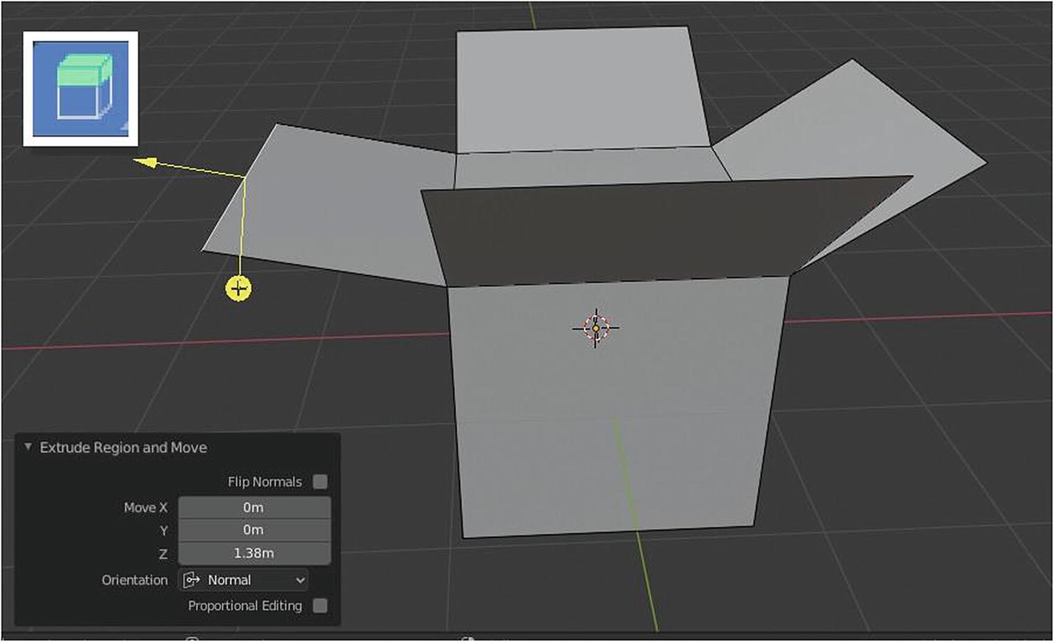
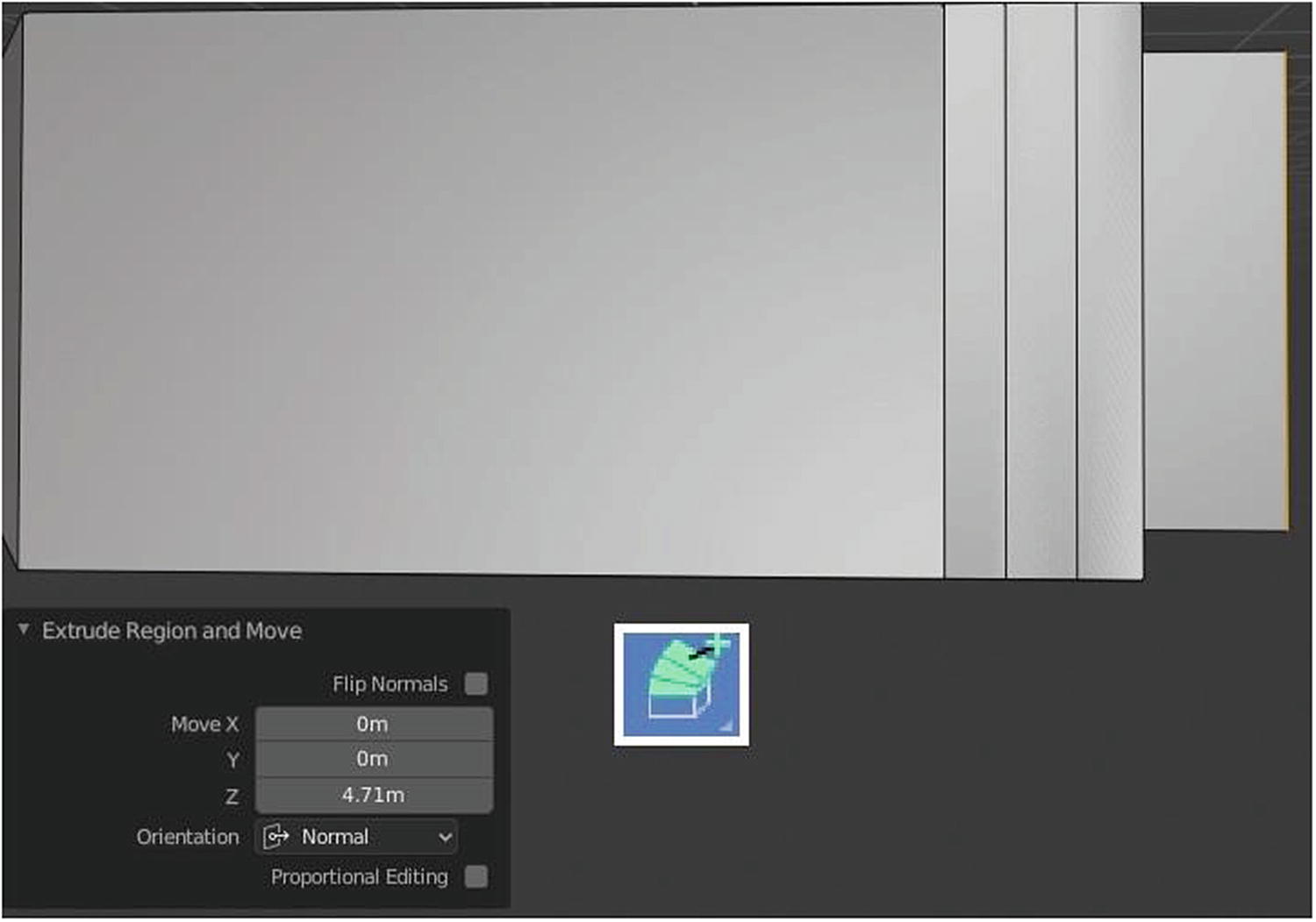
Extrude Region tool and its pop-up menu
Extrude region means extruding one part of a mesh. There is a plus sign opposite the arrow. When you click it, it changes the direction of where you will extrude. If you want to stop extruding, you can click anywhere else and drag to pull new geometry in that direction. By doing this, a circle appears at the base of the plus to allow further manipulation.
There is another pop-up menu at the bottom of the screen, which is related to the Extrude Region tool. In Figure 3-5, the Flip Normals and Orientation select menus are visible under the pop-up menu. When you enable the Flip Normals toggle button, you see the arrow with the plus-sign head change its direction to the opposite side. It is different when you click the arrow with the plus-sign head. When you enable/disable flip normals, the arrow with a plus-sign head changes direction to its opposite side without affecting the other arrow. When you click the arrow with the plus-sign head directly, both arrows change direction. Changing the values of x, y, and z affect the length or width of the extruded part.
Orientation is the transformation orientation of your Extrude Region tool. When you enable Proportional Editing, settings like Proportional Falloff, Proportional Size, Connected, and Projected (2D) show.

Extrude Along Normals tool
There is a double-sided black arrow. When using Extrude Along Normals, it only extrudes in one direction, which is based on the normal of the element you choose to extrude. In Figure 3-5, I extruded the edge facing in the left side. When I enabled Flip Normals, the normals switched direction but not the object. That meant the extruded part went in the opposite direction, which was the right side.
Adjusting the size of the offset adjusts the size of the extruded part. There is proportional editing for this, and the settings are the same as Extrude Region.
Extrude Individual Tool
When you use Extrude Individual on vertices and edges, it either moves or scales the elements.
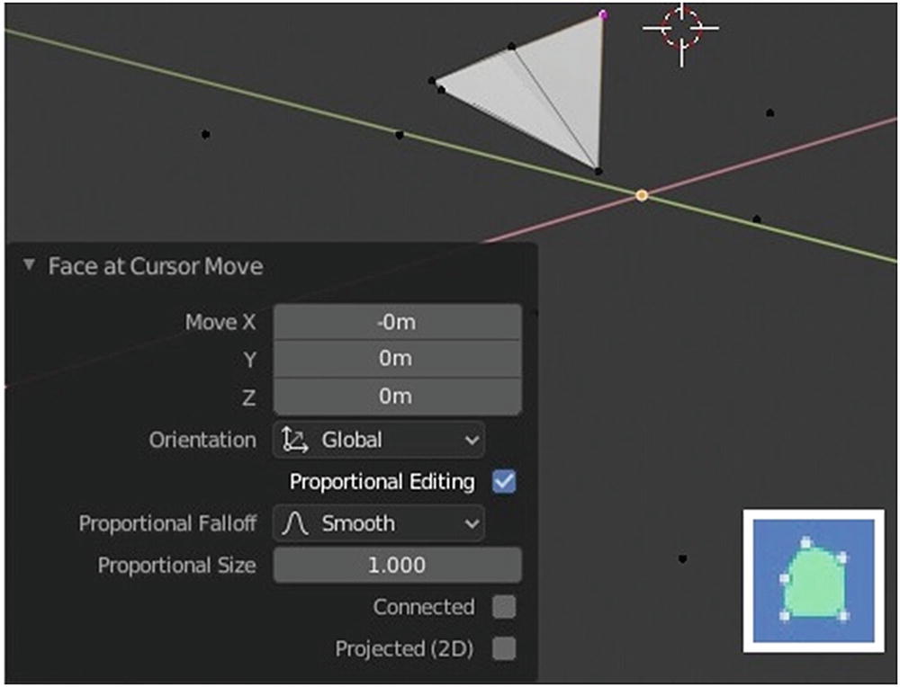
With this tool, when you select a face, it creates other faces to surround it, like a box. In Figure 3-6, the selected face is the one on the left. When I extrude it, it creates other faces in its surroundings.
The icon represents Extrude Individual. It can only extrude faces, as shown in Figure 3-6. Extrude Individual has its own pop-up menu, in which you can set its offset, and it has proportional editing settings.
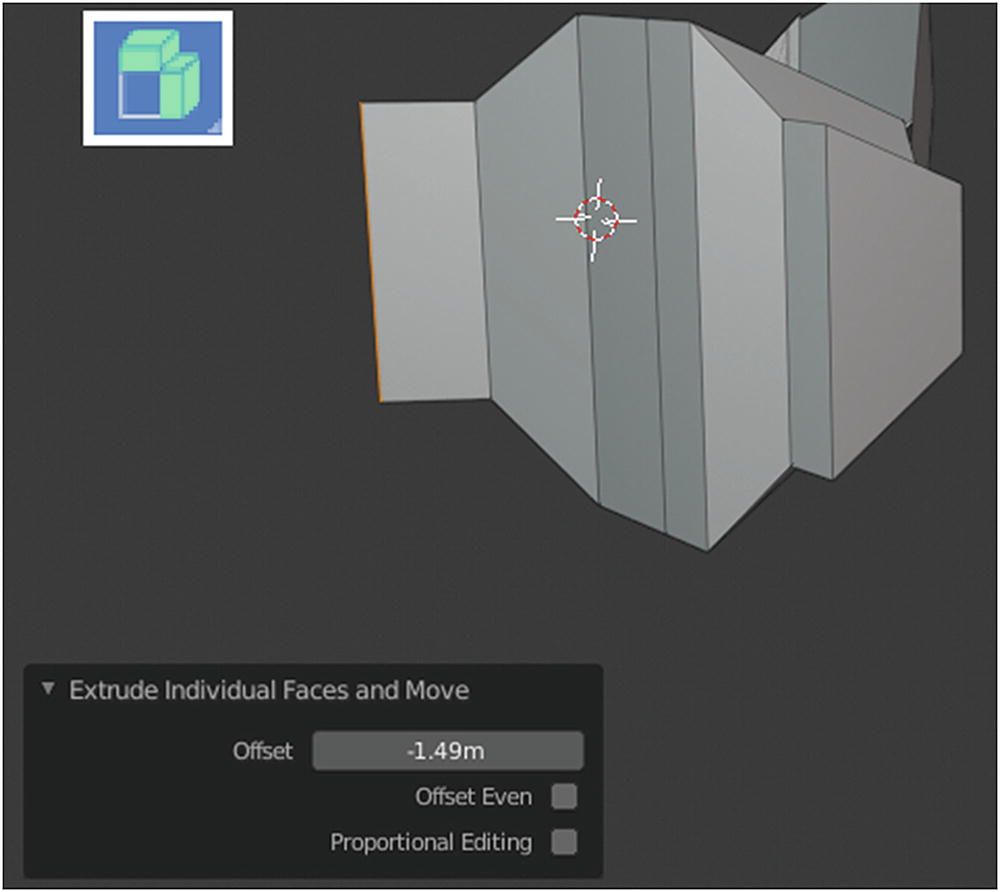
Extrude Individual tool
Extrude to Cursor Tool
Extrude to Cursor tool
This method of extruding means to extrude in the direction in which the mouse cursor is located.
Extrude to Cursor has a toggle box for flipping normals, settings to adjust the x, y, and z axes, and settings for orientation and proportional editing. With this method, I advise that you think before you click because this is the direction in which the extruding happens. But if you accidentally click the mouse, you can undo it.
Inset Tool
The purpose of the Inset tool is to insert new faces in the selected faces, as shown in Figure 3-8. When you adjust thickness in the settings, the inset faces adjust their scope; it depends on the measurement or value given. When you adjust a value in the depth settings, the inset face moves either inward or outward, depending on the value. When you enable Outset, it outsets instead of insets, which means rather than inward, things move outward when inserting new faces. When you enable Select Outer, it selects the new inset faces.
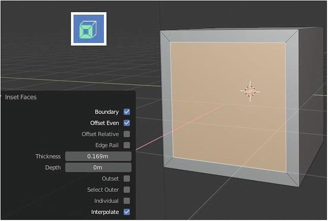
Inset tool
When you enable Individual, it insets the face individually. When you enable Interpolate, it blends the face data across the inset. Boundary insets face boundaries. Offset Even scales the offset to even the thickness. Offset Relative scales the offset of the surrounding geometry. Edge Rail insets the region along existing edges. By default, Boundary, Offset Even, and Interpolate are enabled because the combination of the three is enough to offer a nice inset for basic or simple designs.
Bevel Tool
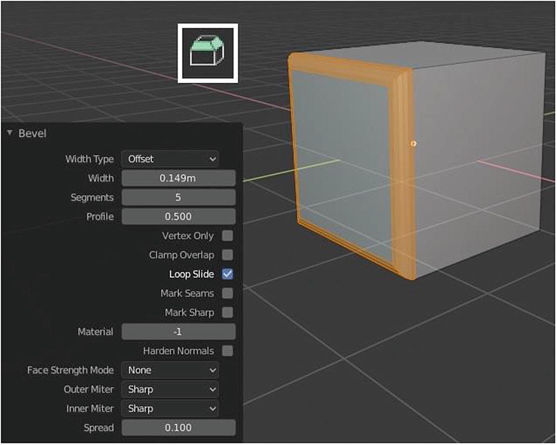
The Bevel is the tool that is most used, especially by those who make photorealistic scenes. In reality, there is no perfect cube, rectangle, or any other shape; that’s why there is the Bevel tool. This tool smooths the edges of a mesh; the amount depends on the settings you make. By default, the segment value is 0, but as you can see in Figure 3-9, the segment value is 5, which makes the edges smoother because it creates five loops around that edges or segments.
The Width value is the scope of the bevel. There are four types: Offset, Width, Depth, and Percent. By default, the Width type is offset.
When you adjust the value of Profile, it changes the way the bevel looks.
When you enable Vertex Only, the bevel is applicable only on the corners, vertices mesh, or edges that are currently selected.
Clamp Overlap prevents the beveled edges or vertices from overlapping.
When Loop Slide is activated, it slides the unbeveled edges along with beveled edges into a vertex. Turning it off can lead to even widths.
Mark Seams is used if you want to mark seams along the beveled edges. Seams are a way to create separations, which are useful for UV mapping.
Mark Sharp marks the beveled edges as sharp. Sharp is used by the edge split modifier, which is a smoothing technique.
Material is the shader or material used in the beveled edges. The material currently selected in the Material panel under the Properties Editor will reflect as the material for the beveled edges. The default number is –1. The material is inherited from the closest existing face; otherwise, the number is the slot index of the material to use for all newly created faces.
When Hardened Normals is enabled, the per-vertex face normals of the bevel face are adjusted to match the surrounding faces, and the normals of the surrounding faces are not affected. This keeps the surrounding faces flat, and with the bevel faces smoothly shading into them.
Face Strength Mode is to set strength face in the faces involved in the bevel mode. There are four options: None, All, Affected, and New. By default, this is set to None.
There is also Outer Miter and Inner Miter. First, what is a miter? A miter is formed when two beveled objects meet at an angle. Outer Miter has three options: Patch, Sharp, and Arc. Inner Miter has two options: Sharp and Arc. When you choose Patch, the edges meet at a sharp point. Two extra vertices are introduced near the point so that the edges and faces at the vertex are less pinched together. When you choose Sharp, the edges meet at a sharp point with no extra vertices introduced on the edges. When you choose Arc, two vertices are introduced near the meeting point, and a curved arc joins them together.
Loop Cut and Offset Edge Loop Cut Tools
The next tools are Loop Cut (Ctrl+R) and Offset Edge Loop Cut (Shift+Ctrl+R).
You can set the number of loop cuts in the pop-up menu for the Loop Cut tool. Adjusting the Smoothness value in the settings makes the loop cut go inward or outward. Falloff is about the smoothness type, and it changes the shape of the profile. Falloff has six types: Linear, Sharp, Inverse Square, Root, Sphere, and Smooth. Factor adjusts the place of the active loop cuts. Enabling Even makes the edge loop match the shape of the adjacent edge loop. Flipped flips the target edge loop to match when Even is enabled.
Offset Edge Loop Cut adds two edge loops on either side of the selected loops, while Loop Cut inserts a new loop intersecting the chosen edge. It has the same settings as Loop Cut except that it does have Cap Endpoint and it doesn’t have Falloff. When you enable Cap Endpoint, it extends the loop around the endpoints.
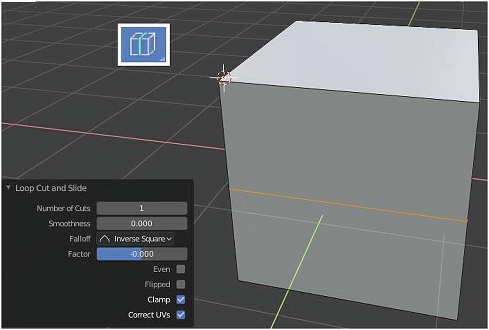
Loop Cut tool at work

Offset Edge Loop Cut tool
Note
If you emulate the numpad, the hotkeys using 0–9 on your keyboard will not work because they are replaced by the numpad tools. For example, 4 is a hotkey for Annotate, but if you are emulating the numpad, it turns into a hotkey for Orbit Left, which originally had a Numpad 4 hotkey. We discuss a lot of hotkeys, but I’d like you to remember this one.
Knife and Bisect Tools

Knife tool at work
Knife, unlike other tools, doesn’t have many settings. It does things like an actual knife in the real world. It cuts the meshes according to the direction you want and creates new vertices; it ends when you hit Enter.

Bisect tool at work
Knife only works in selected faces, but the Bisect tool works on the whole mesh.
As you can see, there is a circle with an arrow inside near a mesh when you used a Bisect tool. This arrow is the basis of the tool’s direction or the axis it will start bisecting.
In the pop-up menu settings, there is Plane Point. When you adjust the value of the x, y, or z axes in Plane Point, you see the arrow and the loop in the Bisect tool move at the same time. Plane Point sets the point in the plane, which is the loop created by the Bisect tool.
Plane Normal is the direction of the plane point. By default, the Bisect tool only divides the existing face, but when you enable Fill, it fills the cut portion of the mesh. Enabling fill connects the vertices created by the Bisect tool, and forms another face. When you enable Clear Inner, it cuts out the geometry behind the plane. Clear Outer cuts out the geometry in front of the plane.
Polybuild Tool
Polybuild tool at work
To use this tool, you need to create a shape from the vertices.
The Polybuild tool is a way to start a mesh. It is more useful when doing retopology. For you to use it, first, create three or four vertices using this tool and then create a face by clicking the F key. When you hover on the edge or in the vertex, it turns pink. Try to drag it using your left mouse button, and you will create another plane. That’s how the Polybuild tool works. Simple, isn’t it?
Spin and Spin Duplicates Tool

Spin tool at work
To use the Spin tool, you must have an existing vertex or vertices that it can extrude. It extrudes in a circular direction. The Spin tool settings are quite simple. Steps indicate the number of vertices to be added in the current vertices in the scene.
The rest of the settings are for rotating, scaling, or moving the mesh in the x, y, or z axes. There is a guide that helps you with this. Figure 3-15 shows the guide for working with the Spin tool. When you hold and drag the blue curve with the plus icon in its head, it creates vertices around it while spinning. When you drag one of the two arrows, the created vertices rotate toward the axis, represented by the arrow you dragged. It’s best to play around with this tool. You might create something amazing from it.
Spin Duplicates is the same as the Spin tool, except that it duplicates the data of the object or the elements.
Smooth Tool
The Smooth tool (Shift+6) flattens angles of the selected vertices. The Randomize tool (Shift+7) randomly arranges selected vertices.
Edge Slide and Vertex Slide Tool

Edge slide at work (left) and vertex slide at work (right)
The settings for Factor are for the distance of the element. Enabling Even makes the edge loop match the shape of the adjacent edge loop. Enabling Flipped makes an edge loop flip between the two adjacent loops when Even is enabled. Enabling Clamp makes an edge clamp within the edge extents. Enabling Correct UVs automatically corrects UV coordinates while transforming.
Shrink/Flatten Tool
The Shrink/Flatten tool (Alt+S) is like a scale tool when you use it in an ordinary mesh, except that it has settings, like proportional editing.
The offset, proportional editing, falloff, and other settings function the same as I discussed in previous tools. What I discuss here is how you visually see the effects of this tool. This tool shrinks and flattens the vertices along normals. For trial purposes, to see its effect, we must first select parts of the mesh.
To feel the effects of proportional editing, you need a lot of vertices.

Shrink/Flatten tool at work
It is more interesting with proportional editing. It should be noted that once you go to the Adjustment panel to enable proportional editing, you can’t click out of the panel. When you play around with the offset and match it with the right proportional editing falloff and size, you can create something amusing.
Push/Pull Tool
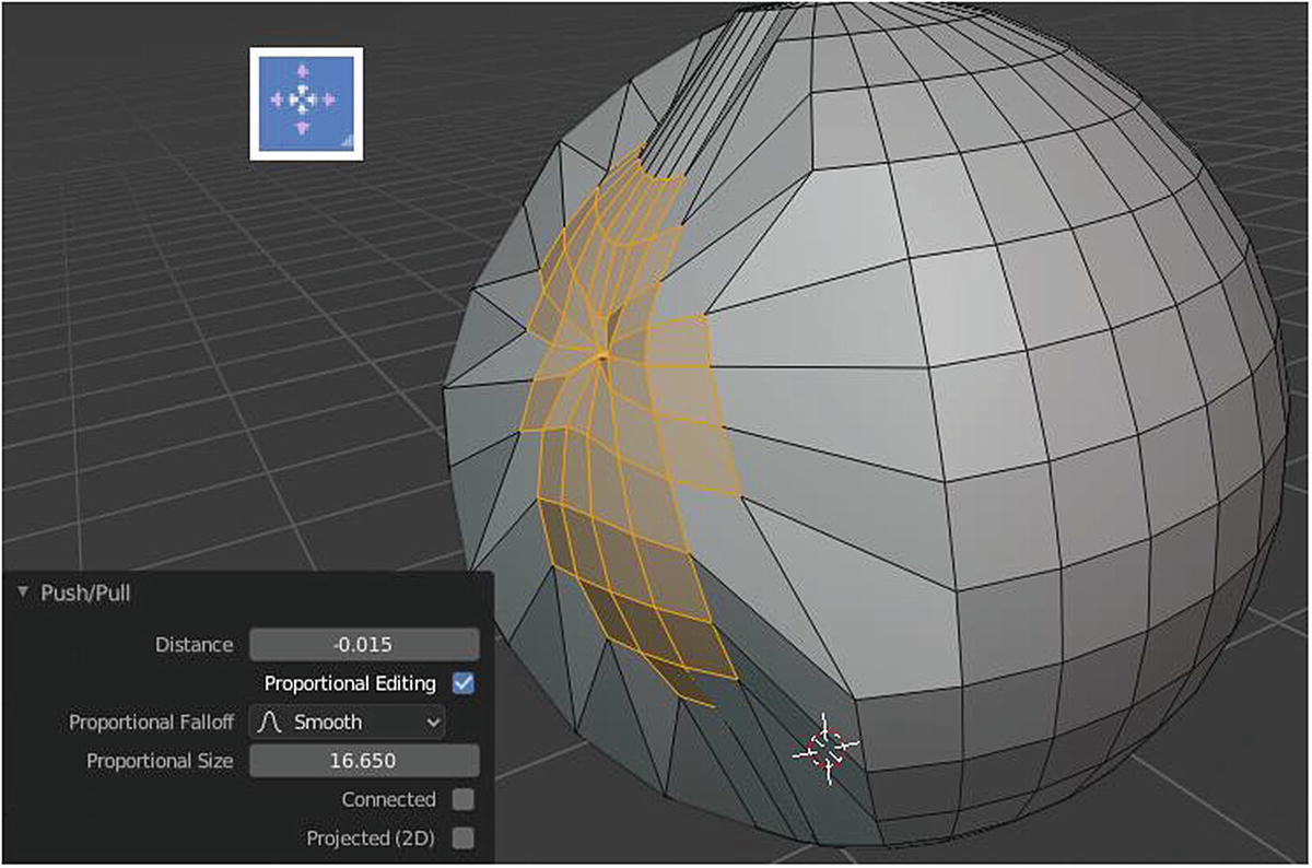
Push/Pull tool at work
This tool has the same settings as the Shrink/Flatten tool except that the Push/Pull tool works directly on the selected element.
Shear Tool
Now, let’s move on to the next tool, which is the Shear tool (Shift+Ctrl+Alt+S). The Shear tool shears selected items along the horizontal axis of the screen.
When you select the Shear tool, there are arrows pointing to different axes appearing on the selected elements to modify. When you click and drag the head of this arrow, which is looks like the letter X, the selected element is sheared to the x axis, of toward the y axis, or even in the z axis; it depends on which direction the X line is pointing to. You can also change the direction by changing the offset value and changing the axis in the Settings panel.
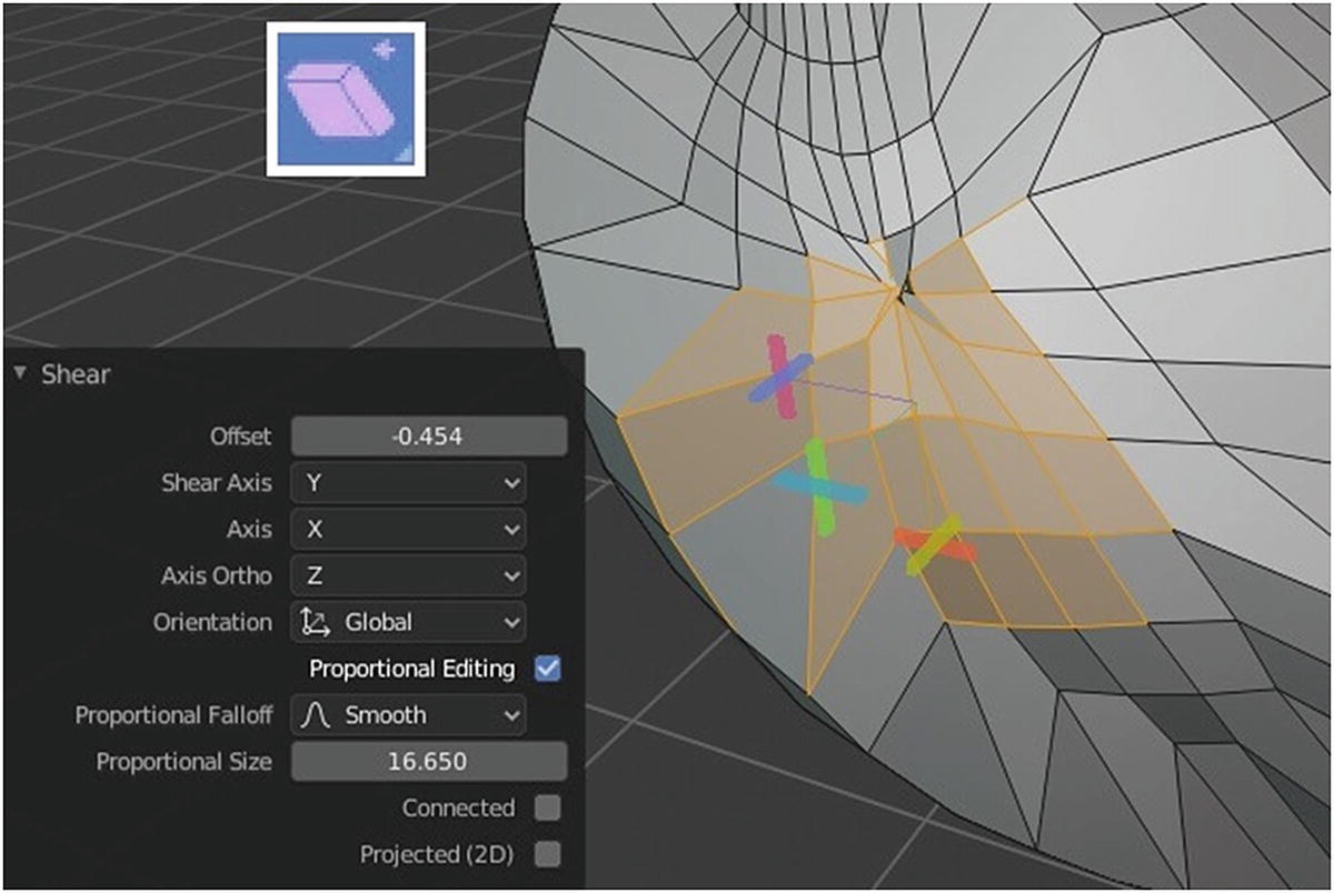
Shear tool at work
To Sphere Tool
The To Sphere tool (Shift+Alt+S) simply moves the vertices in a spherical shape when you create a new face or a new part of the mesh.
Just like in the Shrink/Flatten and Push/Pull tools, the right amount of factor, proportional falloff, and size can give you an amazing outcome. Just explore, experiment, and play. That’s how creativity works!

Experiments using Shrink/Flatten, Push/Pull, Shear, To Sphere tools
Rip Region and Rip Edge Tools
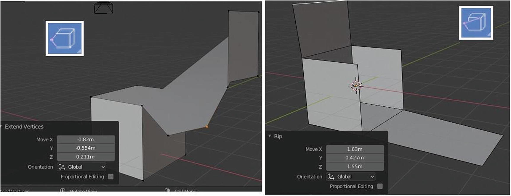
Rip Region (left) and Rip Edge (right)
As you can see in Figure 3-21, Rip Region extends the vertices and automatically connects them to other vertices. Rip Edge extends the edge and cuts or rips it out from the mesh. These tools can only be used with the vertices and the edge.
We’re done with Mesh tools. We’ll proceed to the tools for the Armature object. I will only briefly discuss these tools since they are advanced.
Toolbar ➤ Armature
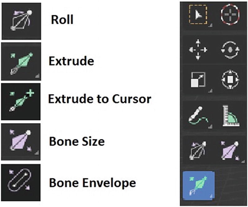
Specific tools (left) and Armature toolbar (right)
Roll (Ctrl+Alt+S) transforms selected items by rotating or rolling.
Bone Size (9) and Bone Envelope (0) transform selected items by mode type. The difference between the two is that Bone Envelope indirectly affects a bone, while Bone Size directly affects a bone.
Extrude (E) creates new bones from the selected joints and moves them.
Extrude to Cursor (Shift+1) extrudes the bones where you click your cursor. (Think before you click.)
Let’s move on to the set of tools for the Grease Pencil object.
Toolbar ➤ Grease Pencil
Specific tools (left) and Grease Pencil toolbar (right)
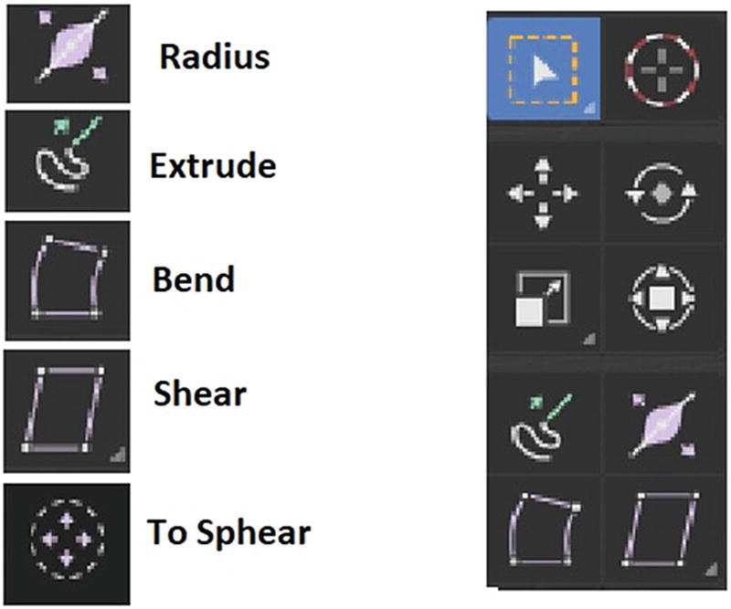
Radius (Alt+S) contracts or expands the radius of the selected points.
Extrude (5) creates another stroke from the selected points.
Bend (Shift+W) bends selected items between the 3D cursor and the mouse.
Shear (Shift+Ctrl+Alt+S) shears selected items along the horizontal screen axis.
To Sphere (Shift+Alt+S) moves selected vertices outward in a spherical shape around the mesh center.
Let’s proceed to the set of tools for Curve objects.
Toolbar ➤ Curve

Specific tools (left) and Curve toolbar (right)
Since what we have for Surface, Lattice and Metaball are only the Select tools, Cursor, Rotate, Scale tools, Transform, Annotate tools and Measure while on Text Objects, what we have are only Cursor, Annotate tools and Measure, I will not explain it since I already discuss those tools in the previous topics.
The Camera, Empty, Force Field, Light, Light Probe, and Speaker objects don’t have an Edit mode; they can only be modified by simple transformations in Object mode. Therefore, they are not part of the Modeling workspace discussion.
Let’s work on a simple project using the tools.
Sample Project
Let’s edit our Suzanne project using a combination of the Layout workspace (or Object mode) and the Modeling workspace (or Edit mode). Remember, Object mode is the default mode for the Layout workspace, and Edit mode is the default mode for the Modeling workspace.
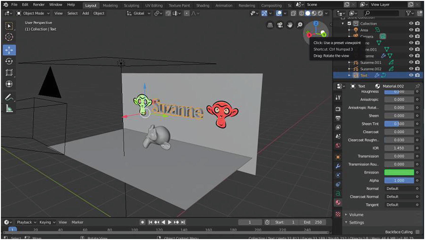
The current setup for Project Suzanne

The Extrude Region and Bevel tools at work on Project Suzanne
First, delete one of the planes and re-create it in the Modeling workspace using the Extrude Region tool. Next, switch from vertex to edge before using the tool. You should choose the bottom edge and extrude it. Then select the edge in the center (the edge that separates the two planes) using the Select tool. Finally, use the Bevel tool and set the segment value to 5.
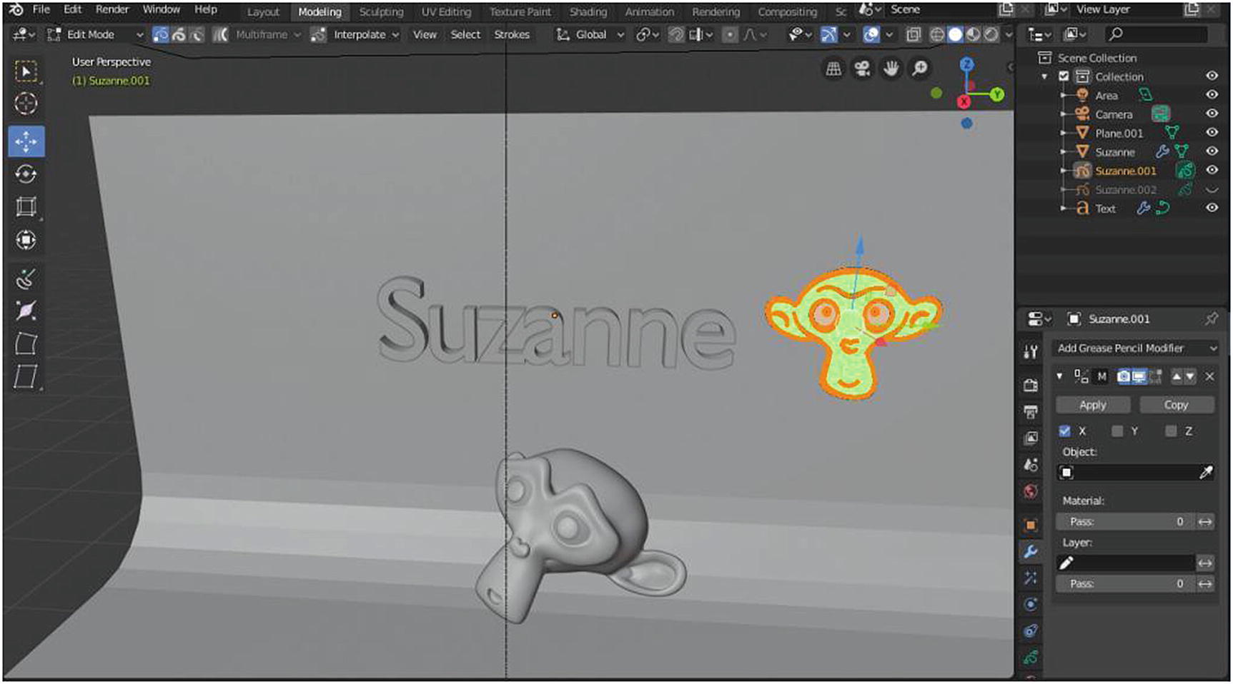
Mirror modifier in Edit mode
Mirror modifier in Object mode
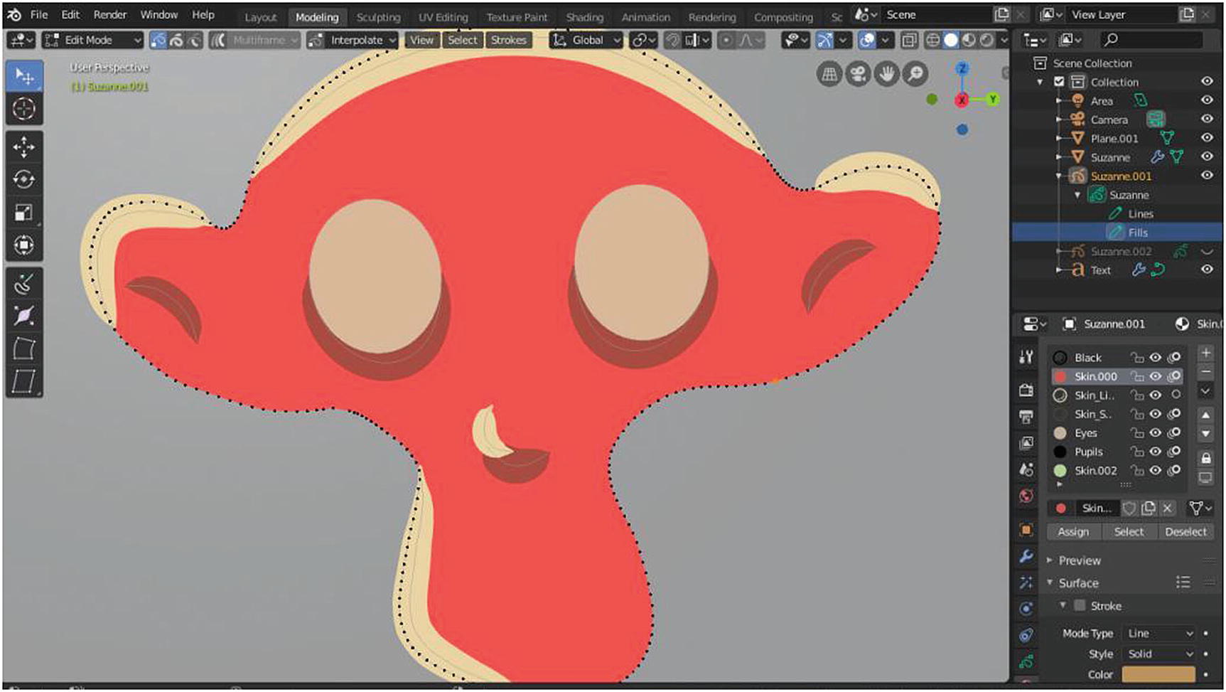
Selecting the part of Grease pencil and assigning material
Compared to the Layout workspace or Object mode, the Materials setting in Edit mode (or the Modeling workspace) has a lot of options. Choose a part of your object, click the material in the panel, and then click the Assign button to apply the material. To add new materials from the list for the same object, you just need to click the plus button. To delete existing materials, click the minus button.
Figure 3-29 shows a close-up.
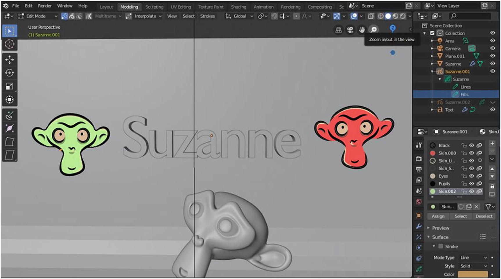
Result of the technique
As you can see in Figure 3-30 and Figure 3-31, although this method might be time-consuming and very detailed, you will be happy with the result.
- 1.
Click the Add button. Set Hair Length to 0.02m and the number value to 20,000.
- 2.
Set Strand Shape to 1, Radius Root to 1.1m, Tip to 0.11m, and Radius Scale to 0.02. There are all settings under Hair Shape.
- 3.
Click Advanced to enable the Rotation setting. Set Randomize to 0.123.
- 4.
Switch from Edit mode to Particle Edit in Mode Type.

Result of the technique, part 2
Make sure that your normal (or the lines sticking out from your mesh object) is facing upward or outside the mesh. Go to Edit mode ➤ Mesh ➤ Normals ➤ Flip Normals.
I’d like to note that once you enter Particle Edit mode and start to edit your particle, you can no longer change your settings in Properties, unless you delete your edits by clicking the Delete Edit button.
Now use Cut (8) in the toolbar to cut the hair from Suzanne’s mouth and eyes. You should also use the Comb tool (3) to comb the hair, and then the Puff tool (7) to make more adjustments. You can add hair using the Add tool (5). Finally, use the Smooth tool (4) to get the desired order of the hair particles.
After you’re satisfied with the hair particles, add materials by using the Edit mode settings for it. You will only apply simple materials here because I have not yet explained the Shading workspace, where you can do more experiments in the Materials settings.

Result of the technique, part 3
The last stage is to adjust the Area light. Change the color a little and adjust the watts to 30. Next, add a subsurface modifier to the plane and add two or three loop cuts to maintain the edges, because when you apply a subsurface modifier in an object, it smoothens the edges of the object to make it look like a circle.

Final render
Still simple? Yes.
We have lots of tools in Blender, like the Particle Edit Mode, which can help you to create awesome scenes.
Let’s proceed to the last workspace. Chapter 4 covers the Shading workspace.