CHAPTER 17
The Art and Technology of Mixing
In the past, almost all commercial music was mixed by an experienced professional recording engineer under the supervision of a producer and/or artist. Although this is still true at many levels of high-end production, with the emergence of the project studio, the vast majority of facilities have become much more personal and cost effective in nature. Additionally, with the maturation of the digital revolution, artists, individuals, labels and enthusiasts are taking the time to gain experience in the artistry, techniques and work-habits of creative and commercial mixing in their own production workspaces.
Within music, audio-for-visual and audio production, it’s a well-known fact that professional mixers have to earn their “ears” by logging countless hours behind the console. Although there’s no substitute for this experience, the mixing abilities and ears of producers and musicians outside of the pro studio environment are also steadily improving as equipment quality gets better and as practitioners become more knowledgeable about proper mixing environments and techniques—quite often by mixing their own projects and compositions.
THE ART OF MIXING
Remember the old music joke: Q: How do you get to Carnegie Hall? A: Practice, kid, practice! Well, the same goes for the process of learning how to mix. In short, mixing is:
■ First and foremost, the art of listening.
■ The art of making decisions based upon what you hear, and then acting upon these decisions.
■ The process of blending art and a knowledge of audio technology and signal flow to turn these decisions into a technological reality, so as to create an artistic vision.
■ An art—as such it’s very subjective and individual. There is no right or wrong way and no two people will mix in exactly the same way. The object of the process is to create a mix that “frames” (shows off) the music in the best light possible.
Listening
It’s a simple fact that no one learns to play an instrument overnight—at least not well. The same goes for the art of listening and making complex judgments within the mixing process. Yet for some reason, we expect ourselves to sit down at a console or workstation and instantly make a masterpiece. I personally remember sitting down at my first recording console (a Neve) and having a go at my first attempt at a mix. I was really nervous and completely unsure of what to do next. I remember moving the faders and saying to myself—ok, now what? Oh yeah, EQ, then I’d start blindly fiddling with the EQ. Well, I’m here to tell you that this is totally normal! You can’t expect to be an expert on your first try, or your second, or your hundredth. Taking time to learn your “instrument” takes time, patience and persistence—after all of this work, you’ll begin to gain enough experience to follow your gut instincts towards creating a professional mix.
EAR TRAINING
Of course, the art of listening requires that you take the time to listen. One of the things that a mix engineer will be doing throughout his or her career is listening to a mix, often over and over. This allows us to become familiar with the nuances of the song and or project. Sometimes, the instant recall aspect of a DAW gives us the ability to keep going back to a mix and improving it adinfinitum. This is often especially true of artists who mix their own work (the it’s never done until it’s “perfect” category). To this, I say; go easy on yourself. Music is often a process of self-discovery and expression. If it were perfect on your first try, how can you expect to get better?
In the twenty-first century, one of the things that we’ve gotten really good at is having media readily at hand. Quite often, this media is omnipresent and totally disposable. You walk into a store—there’s music! A car passes you by— there’s loud music! You go practically anywhere—well, you know the deal all too well. My point is that we’re all too used to being passive in the process. Mixing requires that we become an “active” listener. As such, it’s often a good idea to sit down with your favorite desert island songs, albums, LPs and play them over your best speaker system. How does it sound when you actively listen to them? Then, you might take the time to listen to them over your favorite headphones. How does this change the experience for you? What can you learn from the music and their mixes?
In the end, just as with learning an instrument or doing anything well, the fact remains that as you mix, mix and mix again you will get better at your listening and mixing skills. It’s a matter of experience matched with a desire to do your best.
Preparation
Just as preparation is one of the best ways to ensure that a recording session goes well the idea of preparing for a mix can help make the process go more smoothly and be more enjoyable.
FIXING IT IN THE MIX
The term “fix it in the mix” stems back to the 1980s, when multitrack recording started to hit its full stride. It refers to the idea that if there’s a mistake or something that’s not quite right in the recording “don’t worry about it; we don’t have to make that decision right now; we’ll just fix it later in the mix.” Although to some degree, this might (or might not) be true, the fact is that this mentality can come back to haunt you if care isn’t taken.
From a mix standpoint, preparing for this all-important stage definitely begins in the recording phase. For example, if the above “fix” isn’t dealt with beforehand, it might, indeed be able to be dealt with later. The real problem, however, happens when multiple “fixes” that are meant to be dealt with at a later time begin to creep into the project. If this happens, the mix can take on a new life as something that needs to be wrestled to the ground, in order to sound right instead of being pre-sculpted into a form that will simply need a final polishing in order to shine.
Although, each project has a life of its own, just a few of the ways that a mix can be prepared is to:
■ Strive to capture the artist and performance to disk or tape in a way that best reflects everyone’s artistic intentions. Indeed, decisions such as EQ, EFX, etc., can be made during the mix—but if the life, spirit and essence of the musical expression isn’t captured, no amount of processing during the mix will help.
■ Whenever possible, deal with the musical or technical problem as it occurs, during the recording or production phase.
■ During a punch in or comp session (combining multiple takes into a single, best take), take care to match the tracks as carefully as possible. This might involve documenting the mic and instrument that was used, its placement and distance in the room to the artist, as well as any other detail that will ensure that the tracks properly blend.
■ Create a rough mix during the recording phase that will help you get started toward the final mix. This is especially easy to do in this age of the DAW, as the mix can begin to take its rough form in a way that can be saved and recalled within the session file.
PREPARING FOR THE MIX
REMEMBER:
The mix always has to support the song. It should bring an energy to the performance that allows the musical strengths and statements to shine through.
There are no rules for approaching a mix; however, there are definitely guidelines. For example, when listening to a mix of a song, it is often best to listen to its overall blend, texture and “feel.” A common mistake amongst those who are just beginning their journey into mixing would be to take each instrument in isolation, EQ it and try to sculpt its sound while listening to that track alone. When this is done, it’s quite possible to make each instrument sound absolutely perfect on its own, but when combined into the overall mix, the blend might not work at all. This is because of the subtle interactions that occur when all of the elements are combined. Thus, it’s often a good idea to first listen to the tracks within the context of the full song and then, you can go about making any mix changes that might best serve it.
Preparing for a mix can come in many forms, each of which can save a great deal of setup time, frustration and help with the overall outcome of the project. Here are a few things that can be thought through beforehand:
■ Is the project ready to be mixed? Has sufficient time and emotional energy been put into the vocals? Quite often, the vocals are laid on last—leaving one of the most important elements to the last minute, when there might be time and budget restraints. This leads us to recording rule number 2— ”Always budget enough time to do the vocals right, without stress.”
■ Will you be mixing your own project or will someone else be mixing? If it’s your own project and it’s in-house, then you’re probably technically prepared. If the mix will take place elsewhere, then further thought might be put into the overall process. For example, will the other studio happen to have the outboard gear that you might or will need? Do they have the plug-ins that you’re used to or need for the session? If not, then it’s your job to make sure that you bring the installs and authorizations to get the session up and running smoothly, or print the effects to another track.
■ If you’ll be mixing for another artist and/or producer, it’s often helpful to fully discuss the project with them. Is there a particular sonic style that they’re after? Should the mix be aggressive or smooth sounding? Is there a particular approach to effects that should be taken?
Providing a Reference Track
The band or artist might consider providing the mix engineer with a copy of their own rough or demo mix. This might give insights into how the song might best be mixed, effected or approached.
GAIN STRUCTURE
Actually, I lied when I said that there are no rules to the art of mixing. There is one big one—watching your gain structure. This will be discussed more in-depth later in this chapter; however, it’s worth forewarning you about the perils of setting your record and/or mix faders at levels that will cause distortion. It might be obvious, but the reality of adding just a little bit more here, and a little bit more there will all begin to add up in a mix. Before you know it, your track channels, sub-groups and your main outs will start to redline. Simply being aware of this natural tendency is your best defense again a distorted mix.
HUMAN FACTORS
Given the fact that mixing a song or project is an art, by its very nature it is a subjective process. This means that our outlook and the very way that we perceive a song will affect our workflow, as we approach the mix. Therefore, it’s often a good idea to take care of ourselves and our bodies throughout the process.
■ Try to be prepared and rested as you start the mix process. Working yourself too hard during the recording phase and then jumping right into the mix just might not be the best approach at that point in time.
■ By the same token, over-mixing a song by slaving behind the board for hours and hours on end can definitely effect the way that you perceive a mix. If you’ve gone all blurry-eyed and your ears are tired (the “I can’t hear anything anymore” syndrome)—obviously, the mix could easily suffer. This is definitely a time to point out that you might consider saving your mixes under different version names (i.e., mymix_023), so that you can go back to a previous version, should problems arise.
■ You might want to take breaks—sometimes looooooongg ones. If you’re not under any major time constraint, you might even consider coming back to the mix a day or even a week later. This can give us a fresh perspective, without ear fatigue or any short-term thoughts that might cloud our perception. If this is an option, you might try it out and see if it helps.
A dear friend within the Grammy organization once said to me: “Dave, the one thing that I’ve found amongst all engineers, is the fact that they are seeking that ‘perfect sound’ … it’s something that they ‘hear’ in their heads, but are never quite able to reach that Holy Grail.” From a personal standpoint, I can say that this is true. I’m always sonically reaching for that killer sound, that’s often just beyond reach.
This brings me to: “Wherever you may be, there you are!” By this, I mean; we all have to start somewhere. If you’re just starting out, your level of mix sophistication will hopefully be different than after you’ve had several years of intensive mixing experience under your belt. Be patient with yourself and your abilities, while always striving to better yourself—always a fine line to walk.
From an equipment point-of-view, it’s obvious that you’re not going to start out with your dream system. We all have to start the process by learning what speakers, mics, DAW, etc., will best work for us at our current stage of knowledge, budget and development. Later, your tastes in tools, studio layout and production techniques will surely change—this is all part of growing. Your own personal growth will definitely affect your choice of tools and toys, as well as the way that you integrate with them and your acoustic environment. It’s all part of the personal journey that is called “your life and career.” Be patient with yourself and enjoy the journey.
A REVIEW OF THE RECORDING PROCESS
Before we continue, let’s take a moment out to review the all-important recording and overdub stages which must occur before the mixdown process can begin.
Recording
The recording phase involves the physical process of capturing live or sequenced instruments onto a recorded medium (disk, tape or whatever). Logistically, this process can be carried out in a number of ways:
■ All the instruments to be used in a song or concert can be recorded in a single live pass, either on the stage or in the studio.
■ Musicians can be used to lay down the basic tracks (usually rhythm) of a song, thereby forming the basic foundation tracks, whereby additional instruments can be overdubbed and added to at a later time.
■ Electronic or groove instruments can be performed or programmed into the sound file and/or MIDI sequenced tracks of a DAW in such a way as to build up the foundation of a song.
The first process in this list could involve the recording of a group of musicians as a single ensemble. This is often the case when recording a classical concert in a large hall, where the ensemble and the acoustics of the room are treated as a single entity, which is to be picked up by a microphone array. The recording of a jazz ensemble would often be recorded in a single, live pass, however, in this case the mics will often be placed closer to the instruments, so as to allow for greater control in the mixdown or further production phase. Other styles, such as a rock ensemble, might also record in a single, live pass; although this would most often be recorded using close-mic techniques, so as to take advantage of a maximum amount of isolation during mixdown and further production.
This idea of isolation can also be point of discussion. When recording a classical ensemble, distant miking techniques rely upon the fact that there is little or no isolation between the instruments and their acoustic environment. Recording a classical ensemble for film, for example, will often make use of mic placements that are at a closer, more compromised distance allowing the mics to pick up leakage (bleed) from other instruments, but to a lesser extent, so as to allow for greater control during mixdown. One of the top engineers in the world will often use omnidirectional mics during jazz sessions at a semi-distance to pick up the instruments, nearby leakage and the room stating that leakage can often be a good thing, adding to the “liveness” of the recording. The moral to these examples is that mic distance and isolation are often situational, relying upon the style and intended effect that the room and pickup technique might have upon the music itself—it’s all part of the art of recording.
The last two of the above procedures are most commonly encountered within the recording of modern, popular music. In the second approach, the resulting foundation tracks (to which other tracks can be added at a later time) are called basic, rhythm or bed tracks. These consist of instruments that provide the rhythmic foundations of a song and often include drums, bass, rhythm guitar and keyboards (or any combination thereof). An optional vocal guide (scratch track) can also be recorded at this time to help the musicians and vocalists capture the proper tempo and that all-important feel of a song.
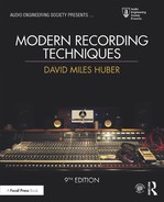
When recording live popular music, each instrument is generally recorded onto separate tracks of an ATR or DAW recorder (Figure 17.1). This is accomplished by plugging each mic into an input strip on the console (or mic panel that’s located in the studio), an input on an audio interface or an available input on a smaller mixer. Once the input is turned on, the input strip/channel gain can be set to its optimum level and is then assigned to a track on a DAW or tape machine.
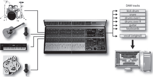
FIGURE 17.1
When recording popular-styled music, each instrument is generally recorded onto a separate track (or stereo tracks) of a recording device.
When approaching the production process from an electronic music standpoint, all bets are off, as there are literally so many possible ways that an artist can build a song, using loops, MIDI instruments and external hardware/software systems (Figure 17.2), that the process often becomes quite personal. This popular form of production can best be understood through a thorough understanding of the DAW (Chapter 7), Groove Tools and techniques (Chapter 8) and MIDI (Chapter 9).
As was said, the beauty behind the modern recording process is that the various instruments can be recorded separately onto tracks of a DAW or ATR recorder, thereby allowing as much isolation between the separately recorded tracks as possible. This is extremely important, as the name of the game is to capture the best performance with the highest possible quality, while achieving optimum isolation between these tracks, and at optimum signal levels (often without regard to level balances on the other tracks).
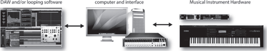
FIGURE 17.2
One possible example of a midi, hardware and software setup.
This last part of the equation refers to the fact that the signal should be recorded to the track at a level that is optimized for the medium. For example, a soft vocal whisper might easily be boosted to recorded levels that are equal to those of a neighboring electric guitar track, or a toy piano might be boosted to the same track level as a full grand piano. In this conventional “one-instrument-per-track” gain setting, each signal should be recorded at a reasonably high level without overloading the digital or analog track. When recording to analog tape, recording at an optimal level will result in a good signal-to-noise ratio, so that tape hiss, preamp noise or other artifacts won’t impair the overall S/N (signal-to-noise) ratio. Digital tracks, on the other hand, are more forgiving (due to the increased headroom, especially at higher 24- and 32-bit-depths). In cases such as these, we might still be in the habit of wanting to record the signal at as high a level as possible (thereby inviting signal clipping or overload distortion). In fact, a properly designed digital signal chain is capable of recording signals over an extremely wide dynamic range, so it’s often a good idea to record signals to disk at lower recommended levels (i.e., quite often peaking at 12 dB below the maximum overload point).
MONITORING
As you might expect, the main benefit of recording individual instruments or instru ment groupings onto isolated tracks at optimum recording levels lay in the fact that project decisions over relative volumes, effects and placement changes can be made at any time during the production and/or final mixdown stage.
Since the instruments have been recorded at levels that probably won’t relate to the program’s final balance, a separate mix must be made in order for the artists, producer and engineer to hear the instruments in their proper musical perspective; for this, a separate mix is often set up for monitoring. As you’ll learn later in this chapter, a multitrack performance can be monitored in several ways. No particular method is right or wrong; rather, it’s best to choose a method that matches your own personal production style or one that matches the current needs of the session and its musicians. This monitor mix can be created and made use of in the control room and in the studio (as a feed to the musicians) in several ways, such as:
■ CR Monitor Mix: The engineer will create a rough mix version of what is being recorded in the studio, so that he or she can hear the tracks in a way that’s musically balanced. If the session is being monitored from within a DAW, digital console or console with automated recall over mix parameters, this ever-evolving control-room mix will often improve over the course of the project, sometimes to the point that the mix improvements can begin to represent the final mix—often making the final mixdown process just that much easier.
■ Studio Monitor Mix: Quite often, this control room mix will be sufficient for the musicians in the studio to hear themselves over headphones in a properly balanced way.
■ Special Studio Cue Mix: Of course, there are times that the musicians as a whole or as individuals will need a special, separate mix in order to properly hear themselves or another instrument from which they will need to take their cues. For example, a musician’s headphone “cue mix” might call for more drums, so the artist can better hear the song’s tempo, or it might call for more piano, so that the vocalist can better stay in tune). It’s totally situational and, at times, multiple cue mixes might be called for. In short, the idea is to do whatever is needed to assist the musicians so that they can best hear themselves in the studio. If they can’t hear themselves in a setting that’s comfortable and best fits their needs it follows that it will be that much harder to deliver their best performance and that, in the end, is the job of a good engineer and producer.
Overdubbing
Instruments that aren’t present during the original performance can be added at a later time to the existing multitrack project during a process known as overdubbing (Figure 17.3). At this stage, musicians listen to the previously recorded tracks over headphones and then play along in sync while recording new and separate tracks that are added to the basic tracks in order to fill out and finish the project.
FIGURE 17.3
Once the basic recorded tracks have been “laid down,” additional tracks can be added at a later time during the overdub phase.
Since the overdub is an isolated take that’s being recorded to a new and separate track, it can be laid down to disk or tape in any number of ways. For example, with proper preparation and talent, an overdub take might get recorded in a single pass. However, if the musician has made minor mistakes during an otherwise good performance, sections of a take could be “punched in” on the same track to correct a bad overdub section. (As a note: most DAWs can do this “nondestructively” i.e., without losing any of the previously recorded data and with the ability to make in/out adjustments at a later time.) For more information on overdubbing to a DAW track, please refer to Chapters 1 and 7, while info on overdubbing in sync to an analog recorder can be found in Chapter 5.
THE TECHNOLOGY OF MIXING
Now that the recording process is complete, we can now return to the technology, techniques and process of mixing. Here, we’ll gain insights into how the console, mixer, digital audio workstation and modern production equipment can work together to improve both your personal working style and your sound.
The basic purpose of an audio production console or mixer (Figures 17.4 through 17.7) is to give us full control over volume, tone, blending and spatial positioning for any or all signals that are applied to its inputs from microphones, electronic instruments, effects devices, recording systems and other audio devices.

FIGURE 17.4
At the console. (a) DMH and Martin Skibba at nhow hotel, Berlin. (Courtesy of nhow Berlin, www.nhowhotels.com/berlin/en, Photo courtesy of Sash) (b) DMH and Emiliano Caballero Fraccaroli. (Courtesy of Galaxy Studios, Mol Belgium, www.galaxy.be)
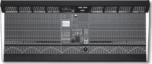
FIGURE 17.5
Solid State Logic Duality Console. (Courtesy of Solid State Logic, www.solid-state-logic.com)
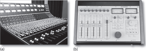
FIGURE 17.6
Smaller analog mixing consoles. (a) API Model 1608. (Courtesy of Automated Processes, Inc., www.apiaudio.com) (b) Rupert Neve Designs 5060 Centerpiece desktop mixer. (Courtesy of Rupert Neve Designs, www.rupertneve.com)
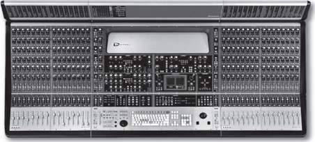
FIGURE 17.7
Digidesign ICON D-Command Integrated console. (Courtesy of Avid Technology, Inc., www.avid.com)
An audio production console (which also goes by the name of board, desk or mixer) should also provide a straightforward way to quickly and reliably route these signals to any appropriate device in the studio or control room so they can be recorded, monitored and/or mixed into a final product. A console or mixer can be likened to an artist’s palette in that it provides a creative control surface that allows an engineer to experiment and blend all the possible variables onto a sonic canvas.
During the mixdown process, the audio project will be repeatedly played while adjustments in level, panning, EQ, effects, etc., are made for each track and/or track grouping. This allows us to get accustomed to the song, soundtrack or audio program, so we can make the appropriate artistic decisions. Throughout this process, the individually recorded signals are then blended into a composite stereo, mono or surround set of output bus tracks that are fed to a master mixdown recorder or more commonly internally “bounced” or “exported” from directly within the DAW’s internal software mixer bus tracks to the final sound file track or tracks. These final mixes can then be assembled or mastered (along with other songs or scenes in the project) into a final product.
When a recording is made “in-the-box” using a DAW, the mixdown process is often streamlined, since the tracks, mixer and effects are all integrated into the software system. In fact, much of the preparation has probably been long underway, as basic mix moves were made and saved into the session during the recording and overdub phases. When working “outside the box,” the process can be quite different (depending upon the type of system that you’re working with). Newer hardware console systems that include facilities to control and communicate directly with the DAW recording system. This integration can be fluid and straightforward, with many or all of the console level, routing and effects settings being recalled directly onto the console’s surface. Fully analog consoles will require that you manually set up and recall all of the session settings each and every time that you need to return to the session. Obviously, this means that most non-automated mix sessions must be repeatedly perfected and “performed” in real-time until a final mix is achieved.
Of course, there are several ways that a mix can be recorded to its final intended mix medium.
■ The DAW or console outputs can be recorded to a digital or analog recorder.
■ The outputs can be recorded onto a new set of tracks on the DAW.
■ An in-the-box mix can be internally exported (bounced) to a final stereo or multichannel mix (either in real or non-real-time).
UNDERSTANDING THE UNDERLYING CONCEPT OF “THE MIXING SURFACE”
In order to understand the process of mixing, it’s important that we understand one of the most important concepts in all of audio technology: the signal chain (also known as the signal path). As is true with literally any audio system, a recording mixer or console (DAW, digital or otherwise) can be broken down into functional components that are chained together into a larger (and hopefully manageable) number of signal paths. By identifying and examining the individual components that work together to form this chain, it becomes easier to understand the basic layout of any mixing system, no matter how large or complex. In order to gain insights into the layout of a mixer, let’s start with the concept that it’s built of numerous building-block components, each having an input that moves to its output, and then to the input of the next functional block to its output and so forth down the signal path until the end of the chain is reached. Here are a few important things to keep in mind, regarding any audio signal chain path:
■ Naturally, whenever a link in this source-to-destination path is broken (or incorrectly routed), no signal will pass. In the heat of production, it’s easy to plug something into the wrong input or output. Following the “gozintagozouta” approach might seem like a simple concept; however keeping it always in mind can save your sanity and your butt when paths, devices and cables that look like tangled piles of spaghetti get out of hand.
■ Try to run each block in the signal chain at its optimum gain level. Too little signal will result in increased noise, while too much will result in increased distortion. We’ll talk more about this later.
■ The “Good Rule” definitely applies to the audio signal path. That’s to say that the overall signal path is no better than its weakest link. Just something to keep in mind.
The Mixer/Console Input Strip
Let’s start our quest into the hardware side of mixing by taking a conceptual look at various systems—from the analog hardware mixer to the general layout within a virtual mixing environment. In a traditional hardware mixer (which also goes by the name of board, desk or console) design, the signal flow for each input travels vertically down a plug-in strip known as an I/O module (Figure 17.8) in a manner that generally flows:

FIGURE 17.8
General anatomies of input strips on an analog mixing console: (a) Mackie Onyx 4-bus. (Courtesy of Loud Technologies, Inc., www.mackie.com); (b) Audient sp8024 large format recording console. (Courtesy of Audient Limited, www.audient.com)
Although the layout of a traditional analog hardware mixer generally won’t match the graphical user interface (GUI) layout of a virtual DAW mixer, the signal flow will follow along the same or similar paths. Therefore, grasping the concept of an analog console’s signal chain will also be extremely useful for grasping the general signal flow concept for smaller mixers and virtual DAW mixers. Each system type is built from numerous building-block components, having an input (source) that flows through the signal chain to an output (destination). The output of each source device must be literally or virtually connected to the input of the device that follows it, and so on until the end of the audio path is reached. Keeping this simple concept in mind is important when paths, plug-ins and virtual paths seem to meld together into a ball of confusion. When the going gets rough, slow down, take a deep breath, read the manual (if you have the time and inclination)—and above all be patient and keep your wits about you.
Figure 17.9 shows the general I/O stages of three virtual mixing systems. It’s important that you take the time to familiarize yourself with the inner workings of your own DAW (or those that you might come in contact with) by reading the manual, pushing buttons and by diving in and having fun with your own projects.
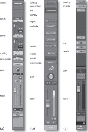
FIGURE 17.9
Virtual mixer strip layouts: (a) Pro Tools. (Courtesy of Avid Technology, Inc., www.avid.com); (b) Logic. (Courtesy of Apple Inc., www.apple.com); (c) Steinberg’s Cubase and Nuendo virtual mixer. (Courtesy of Steinberg Media Technologies GmbH, a division of Yamaha Corporation, www.steinberg.net)
GAIN LEVEL OPTIMIZATION
As we enter our discussion on console and mixer layouts, it’s extremely important that we touch base on the concept of signal flow or gain level optimization. In fact, the idea of optimizing levels as they pass from one device to another or from one functional block in an input strip to the next is one of the more important concepts to be grasped in order to create professional-quality recordings. Although it’s possible to go into a great deal of math in this section, I feel that it’s far more important that you understand the underlying principles of level optimization, internalize them in everyday practice and let common sense be your guide. For example, it’s easy to see that, if a mic that’s plugged into an input strip is overdriven to the point of distortion, the signal following down the entire path will be distorted. By the same notion, driving the mic preamp at too low a signal will require that it be excessively boosted at a later point in the chain, resulting in increased noise. From this, it follows that the best course of action is to optimize the signal levels at each point along the chain (regardless of whether the signal path is within an input strip or pertains to input/output (I/O) levels as they pass from one device to another throughout the studio).
So, now that we have a fundamental idea of how a hardware and software mixing system is laid out, let’s discuss the various stages in greater detail as they flow through the process, starting with a channel’s input, through the various processing and send stages and then out to the final mix bus destination.
1 CHANNEL INPUT (PREAMP)
The first link in the input chain is the channel input (Figure 17.10). This serves as a preamp section to optimize the signal gain levels at the input of an I/O module before the signal is processed and routed. On a hardware console, mixer or audio interface that has built-in mic preamps, either a mic or line input can be selected to be the signal source (Figure 17.11). Although these values vary between designs, mic trims are typically capable of boosting a signal over a range of +20 to +70 dB, while a line trim can be varied in gain over a range of –15 (15-dB pad) to +45 dB or more. Gain trims are a necessary component in the signal path, because the output level of a microphone is typically very low (–45 to –55 dB) and requires that a high-quality, low-noise amp be used to raise and/or match the various mic levels in order for the signal to be passed throughout the console or DAW at an optimum level (as determined by the system’s design and standard operating levels).
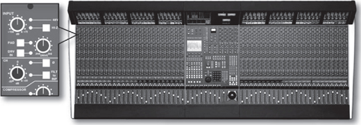
FIGURE 17.10
Channel input section of the Solid State Logic Duality Console. (Courtesy of Solid State Logic, www.solid-state-logic.com)

FIGURE 17.11
Analog and DAW interface input sections. (Courtesy of Loud Technologies, Inc., www.mackie.com and Steinberg Media Technologies GmbH, www.steinberg.net)
Of course, a mic preamp can take many forms. It might be integrated into a console or mixers input strip (as referred to above), or it might exist as external hardware “preze” (Figure 17.12) that are carefully chosen for its pristine or special sound character or it might be directly integrated into our workstation’s own audio interface. Any of these options are a valid way of boosting the mic’s signal to a level that can be manipulated, monitored and/or recorded.
When asked about her recommendations for getting those vintage, quirky analog-type sounds. Sylvia Massy (Prince, Johnny Cash, System of a Down)said, “Try some different things, especially with the mic pres, the front end. The recorder is sorted out, but it’s the front-end that’s the challenge.”

FIGURE 17.12
Microphone preamps: (a) Presonus ADL-600 high-voltage tube preamp. (Courtesy of Presonus Audio Electronics, Inc., www.presonus.com); (b) Universal Audio 2–610S dual channel tube preamp. (Courtesy of Universal Audio, www.uaudio.com © 2017 Universal Audio, Inc. All rights reserved. Used with permission)
Whenever a mic or line signal is boosted to levels that cause the preamp’s output to be overdriven, severe clipping distortion will almost certainly occur. To avoid the dreaded LED overload light, the input gain must be reduced (by simply turning down the gain trim or by inserting an attenuation pad into the circuit). Conversely, signals that are too low in level will unnecessarily add noise into the signal path. Finding the right levels is often a matter of knowing your equipment, watching the meter/overload displays and using your experience.
Input attenuation pads that are used to reduce a signal by a specific amount (e.g., –10 or –20 dB) may be inserted ahead of the preamp, in order to prevent input overload. On many consoles, the preamp outputs may be phase-reversed, via the “Ø” button. This is used to change the signal’s phase by 180º in order to compensate for polarity problems in mic placement or in cable wiring. High- and low-pass filters may also follow the pre-amp, allowing extraneous signals such as amp/tape hiss or subsonic floor rumble to be filtered out.
From a practical standpoint, level adjustments usually begin at the mic preamp. If the pre has LED or other types of metering, setting your gain at a reasonable level (while being careful not to overload this important first major gain stage in the process) will generally get you off to a good start. Alternatively, you could set the gain on the main strip fader to 0 dB (unity gain). While monitoring levels for that channel or channel grouping, turn the mic preamp up until an acceptable gain is reached. Should the input overload LED light up, back off on the input level and adjust the output gain structure accordingly. Care should be taken when inserting devices into the signal chain at a direct insert point, making sure that the in and out signals are also working at or near their optimum level. In addition, it’s important to keep in mind that the EQ section can also cause level overload problems whenever a signal is overly boosted within a frequency range.
Hardware Console/Mixer Insert Point
Many mixer and certain audio interface designs provide a break in the signal chain that occurs after the channel input. A direct send/return or insert point (often referred to simply as direct or insert) can be used to send the strip’s line level audio signal out to an external gain or effects processing device. The external device’s output signal can then be inserted back into the signal path, where it can be mixed back into the audio program. Access to an insert point on a hardware console or mixer can be found at either a marked set of jacks on the studio’s patch bay or at the rear of some console/mixers themselves (Figure 17.13). It’s important to note that plugging a signal processor into an insert point will only affect the audio on that channel.
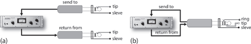
FIGURE 17.13
Direct send/return signal paths. (a) Two jacks can be used to send signals to and return signals from an external device. (b) A single TRS (stereo) jack can be used to insert an external device into an input strip’s path.
Virtual DAW Insert Point
Within a workstation environment, inserts are extremely important in that they allow audio or MIDI processing/effects plug-ins to be directly inserted into the virtual path of that channel (Figure 17.14). Often, a workstation allows multiple plug-ins to be inserted into a channel in a stacked fashion, allowing complex and unique effects to be built up. Of course, keep in mind that the extensive use of insert plug-ins can eat up processing power. Should the stacking of multiple plug-ins become a drain on your CPU (something that can be monitored by watching your processor usage meter—aka “busy bar”), many DAWs allow the track to be frozen (committed), meaning that the total sum of the effects can be written to an audio file, allowing the track + effects to be played back without causing any undue strain on the CPU.

FIGURE 17.14
An effects plug-in can be easily inserted into the virtual path of a DAW’s channel strip. (Courtesy of Avid Technology, Inc., www.avid.com, Steinberg Media Technologies GmbH, www.steinberg.net, and Universal Audio, www.uaudio.com)
2 AUXILIARY SEND SECTION
In a hardware or virtual setting, the auxiliary (aux) sends are used to route and mix signals from multiple input strip channels to a single effect device/plug-in and/or monitor/headphone cue send from within the console or DAW. This section is used to create a mono or stereo sub-mix that’s derived from multiple console or DAW input signals, and then “send” it to a signal processing, monitoring or recording destination (Figure 17.15).
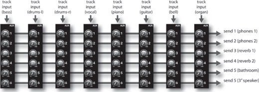
FIGURE 17.15
Although a hardware mixer’s input path generally flows vertically from top to bottom, an aux send’s path flows in a horizontal fashion, in that the various channel signals are mixed together to feed a mono or stereo send bus. The combined mix can then be sent to any device. (Courtesy of Loud Technologies, Inc., www.mackie.com)
It’s not uncommon for six or more individual aux sends to be found on a hardware or virtual input strip. An auxiliary send can serve many purposes. For example, one send could be used to drive a reverb unit, signal processor, etc., while another could be used to drive a speaker that’s placed in that great sounding bathroom down the hall. A pair of sends (or a stereo send) could also be used to provide a headphone mix for several musicians in the studio, while another send could feed a separate mix to the drummer that’s having a hard time hearing the lead guitar. From these and countless other situations, you can see how a send can be used for virtually any signal routing, effects processing and/or monitoring task that needs to be handled. How you make use of a send is up to you, your needs and your creativity.
With regard to a workstation, using an aux send is a great way to use processing effects, while keeping the processing load on the CPU to a minimum (Figure 17.16). For example, let’s say that we wanted to make wide use of a reverb plug-in that’s generally known to be a CPU hog. Instead of separately plugging this reverb into a number of tracks as inserts, we can greatly save on processing power by plugging the reverb into an aux send bus. This lets us selectively route and mix audio signals from any number of tracks and then send the summed (mixed) signals to a single plug-in that can then be mixed back into the master output bus. In effect, we’ve cut down on our power requirements by routing a creative effects mix to a single device, instead of plugging the device into each channel. Knowing the functional difference between an insert and a send can be a powerful engineering tool.

FIGURE 17.16
An effects plug-in can be inserted into an effects send bus, allowing multiple channels to share the same effects processor. (Courtesy of Avid Technology, Inc., www.avid.com, Steinberg Media Technologies GmbH, www.steinberg.net and Universal Audio, www.uaudio.com)
3 EQUALIZATION
The most common form of signal processing is equalization (EQ). The audio equalizer (Figure 17.17) is a device or processing circuit that lets us control the relative amplitude of various frequencies within the audible bandwidth. Like the auxiliary sends, it derives its feed on a hardware console directly from the channel input section. In short, it exercises tonal control over the harmonic or timbral content of an input signal. EQ may need to be applied to a single recorded channel, to a group of channels or to an entire program (often as a step in the mastering process) for any number of other reasons, including:
■ To correct for specific problems in an instrument or in the recorded sound (possibly to restore a sound to its natural tone)
■ To overcome deficiencies in the frequency response of a mic or in the sound of an instrument
■ To allow contrasting sounds from several instruments or recorded tracks to better blend together in a mix
■ To alter a sound purely for musical or creative reasons.

FIGURE 17.17
Equalizer examples. (Courtesy of Loud Technologies, Inc., www.mackie.com, Steinberg Media Technologies GmbH, www.steinberg.net and Universal Audio, www.uaudio.com)
When you get right down to it, EQ is all about compensating for deficiencies in a sound pickup, or “shaping” the sound of an instrument so that it doesn’t interfere with other instruments in a mix or reducing extraneous sounds that make their way into a track. To start our discussion on how to apply EQ, let’s take another look at the “Good Rule.”
The “Good Rule”
Good musician + good instrument + good performance + good acoustics + good mic + good placement = good sound.
Let’s say that at some point in the “good” chain something falls short—like, a mic was placed in a bad spot for a particular instrument during a session that’s still in progress. Using this example, we now have two options. We can change the mic position and overdub the track or re-record the entire song—or, we can decide to compensate by applying EQ. These choices represent an important philosophy that’s held by many producers and engineers (including myself): Whenever possible, EQ should NOT be used as a bandage to doctor a track or session after it’s been completed. By this, I mean that it’s often a good idea to correct a problem on the spot during the recording (i.e., change the mic or mic position) rather than rely on the hope that you can fix it later in the mix using EQ and other corrective methods.
Although it’s usually better to deal with problems as they occur, this simply isn’t always possible. When a track needs fixing after it’s already been recorded, EQ can be a good option when:
■ There’s no time, money or possibility to redo the track.
■ The existing take was simply magical and too much feeling would be lost if the track were to be redone.
■ You have no control over a track that’s already been recorded during a previous session and the artists are touring on the other side of the planet.
Whenever EQ is applied to a track, bus or signal, the whole idea is to take out the bad and leave the good. If the signal is excessively EQed, the signal will often degrade and lead to volumes that often creep up in level. Thus, it’s often a good idea to use EQ to take away a deficiency in the signal and not simply boost the desirable part of the track. Just a few examples of using EQ to cut offensive sounds might include:
■ Reducing the high end on a bass guitar instead of boosting its primary bass notes
■ Using a peak filter to pull out the ring of a snare drum (a perfect example of a problem that should’ve been corrected during the session, by dampening the drumhead)
■ Pulling out a small portion of a vocalist’s upper-midrange to reduce any problematic nasal sounds
It’ s always a good idea to be patient with your “EQ style”——especially when you’re just starting out. Learning how to EQ properly (i.e., not over EQ) takes time and practice.
Using EQ might or might not always be the best course of action. Just like life, use your best judgment—nothing’s ever absolute. A complete explanation of equalization can be found in Chapter 15 (Signal Processing).
4 DYNAMICS SECTION
Many top-of-the-line analog consoles offer a dynamics section on each of their I/O modules (Figure 17.18), and of course dynamic plug-ins are readily available for all DAWs. This allows individual signals to be dynamically processed more easily, without the need to scrounge up tons of outboard devices. Often, a full complement of compression, limiting and expansion (including gating) is also provided. A complete explanation of dynamic control can be found in Chapter 15 (Signal Processing).

FIGURE 17.18
Dynamics section of a Solid State Logic Duality Console. (Courtesy of Solid State Logic, www.solid-state-logic.com)
5 MONITOR SECTION
During the recording phase, since the audio signals are commonly recorded to DAW or tape at their optimum levels (without regard to the relative musical balance on other tracks), a means for creating a separate monitor mix in the control room is necessary in order to hear a musically balanced version of the production. Therefore, a separate monitor section (or aux bus) can be used to provide varying degrees of control over each input’s level and possibly panning, effects, etc. This mix can be routed to the master CR volume control, as well as monitor switching between various speaker sets and between mono, stereo or surround modes in the control room (Figure 17.19). The approach and techniques for monitoring tracks during a recording will often vary from mixer to mixer (as well as among individuals). Again, no method is right or wrong.
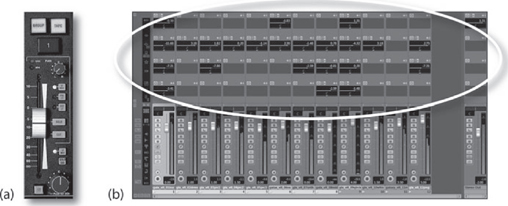
FIGURE 17.19
Monitor mix sections: (a) Legacy model SSL XL9000K monitor mix section. (Courtesy of Solid State Logic, www.solid-statelogic.com); (b) Software monitor section (at top) within the Cubase/Nuendo virtual mixer. (Courtesy of Steinberg Media Technologies GmbH, www.steinberg.net)
It simply depends on what type of equipment you’re working with, and on your own personal working style.
Note that during the overdub and general production phases on a large-scale console or DAW, this idea of using a separate monitor section can be easily passed over in favor of mixing the tracks directly using the main faders in a standard mixdown environment. This straightforward process helps us by setting up a rough mix all through the production phase, allowing us to finesse the mix during production under automated recall. By the time the final mix rolls around, many of your “mix as you go” level and automation kinks might easily have been worked out.
In-Line Monitoring
Many larger console designs incorporate an I/O small fader section that can be used to directly feed its source signal to the monitor mix or directly to the DAW/ATR (depending on its selected operating mode). In the standard monitor mix mode (Figure 17.20a), the small fader is used to adjust the monitor level for the associated recording track. In the flipped mode (Figure 17.20b), the small fader is used to control the signal level that’s being sent to the recording device, while the larger, main fader is used to control the monitor mix levels. This useful function allows multitrack record levels (which aren’t often changed during a session) to be located out of the way, while the more frequently used monitor levels are assigned to the larger, more accessible master faders.
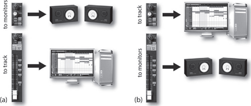
FIGURE 17.20
Flipped-fader monitor modes: (a) standard monitor mode; (b) flipped monitor mode.
Direct Insert Monitoring
Another flavor of in-line monitoring that has gained favor over the years is known as direct insert monitoring. This method (which often makes the most sense on large-format consoles) makes use of the direct send/returns of each input strip to insert the recording device (such as a DAW) directly into the input strip’s signal path. Using this approach (which is closely tied to the Insert Point section from earlier in the chapter),
■ The insert send output for each associated channel (which can be inserted either before or after the EQ section) is routed to its associated track on a multitrack DAW or ATR.
■ The insert return signal is then routed back from the recording device’s output back into the console’s input strip return path, where it’s injected back into the channel strip’s effects send, pan and main fader path.
With this approach, the input signal directly following the mic/line preamp will be fed to the DAW or ATR input (with record levels being adjusted by the pre-amp’s gain trim). The return path (from the DAW or ATR) is then fed back into the input strip’s signal path so it can be mixed (along with volume, pan, effects, sends, etc.) without regard for the levels that are being recorded to tape, disk or other medium. This system greatly simplifies the process, since playing back the track won’t affect the overall monitor mix at all—because the recorder’s outputs are already being used to drive the console’s monitor mix signals.
Separate Monitor Section
Certain British consoles (particularly those of older design) incorporate a separate mixing section that’s dedicated specifically to the task of sending a mix to the monitor feed. Generally located on the console’s right-hand side (Figure 17.21), the inputs to this section are driven by the console’s multitrack output and tape return buses, and offer level, pan, effects and “foldback” (an older British word for headphone monitor control). During mixdown, this type of design has the distinct advantage of offering a large number of extra inputs that can be assigned to the main output buses for use with effects returns, electronic instrument inputs and so on. During a complex recording session, this monitoring approach will often require an extra amount of effort and concentration to avoid confusing the inputs that are being sent to tape or DAW with the corresponding return strips that are being used for monitoring. This is especially true when the channel and track numbers do not agree (which is probably why this design style has fallen out of favor in modern console designs).
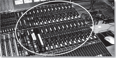
FIGURE 17.21
Older style English consoles may have a separate monitor section (circled), which is driven by the console’s multitrack output and/or tape return buses. (Courtesy of Buttermilk Records, www.buttermilkrecords.com)
6 CHANNEL FADER
Each input strip contains an associated channel fader, which determines the strip’s bus output level (Figure 17.22) and pan pot which is often designed into or near the fader and determines the signal’s left/right placement in the stereo and/or surround field (Figure 17.23). Generally, this section also includes a solo/mute feature, which performs the following functions:
■ Solo: When pressed, the monitor outputs for all other channels will be muted, allowing the listener to monitor only the selected channel (or soloed channels) without affecting the multitrack or main stereo outputs during the recording or mixdown process.
■ Mute: This function is basically the opposite of the solo button, as when it is pressed the selected channel is cut or muted from the main and/or monitor outputs.
Depending on the hardware mixer or controller interface design, the channel fader might be motorized, allowing automation moves to be recorded and played back in the physical motion of moving faders. In the case of some of the high-end console and audio interface/controller designs, a flip fader mode can be called up that literally reassigns the control of the monitor section’s fader to that of the main channel fader (as was seen in Figure 17.20). This “flip” allows the monitoring of levels during the recording process to be controlled from the larger, long-throw faders. In addition to swapping monitor/channel fader functions, certain audio interface/controller designs allow a number of functions such as panning, EQ, effects sends, etc., to be swapped with the main fader, allowing these controls to be finely tuned under motorized control.
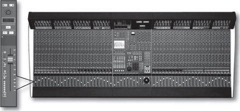
FIGURE 17.22
Output fader section of the Solid State Logic Duality Console. (Courtesy of Solid State Logic, www.solid-state-logic.com)
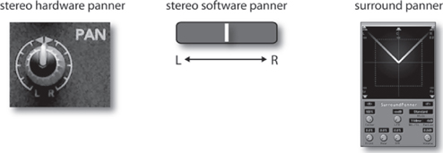
FIGURE 17.23
Example of various hardware and software pan pot configurations.
7 OUTPUT SECTION
In addition to the concept of the signal path as it follows through the chain, there’s another important signal concept that should be understood: output bus. From the above input strip discussion, we’ve seen that a channel’s audio signal by and large follows a downward path from its top to the bottom; however, when we take the time to follow this path, it’s easy to spot where audio is sometimes routed off the strip and onto a horizontal output path. Conceptually (and sometimes literally), we can think of this path (or bus) as a single electrical conduit that runs the horizontal length of a console or mixer (Figure 17.24). Signals can be inserted onto or routed off of this bus at multiple points.
Much like a city transit bus, this signal path follows a specific route and allows audio signals to get on or off the line at any point along its path. Aux sends, monitor sends, channel assignments, and main outputs are all examples of signals that are taken from their associated input strips and are injected into buses for routing to one or more output destinations. The main stereo or surround buses, (which are used to feed the channel faders and pan positioners) are then fed to the mixer’s main output bus, where they are combined with the various effects return signals and finally routed to the recording device and/or monitor speakers.

FIGURE 17.24
Example of a master output bus, whereby multiple inputs are mixed and routed to a master output fader.
8 CHANNEL ASSIGNMENT
After the channel output fader on a console or larger mixer, the signal is often routed to the strip’s track assignment matrix (Figure 17.25), which is used to distribute the signal to any or all tracks of a connected multitrack DAW or ATR recorder. Although this section electrically follows either the main or small fader section (depending on the channel’s monitor mode), the track assign buttons will often be located either at the top of the input strip or designed into the main output fader (often being placed at the fader’s right-hand side). Functionally, pressing any or all assignment buttons will route the input strip’s main signal to the corresponding track output buses. For example, if a vocal mic is plugged into channel 14, the engineer might assign the signal to track 14 by pressing (you guessed it) the “14” button on the matrix. If a quick overdub on track 15 is also needed, all the engineer has to do is unpress the “14” button and reassign the signal to track 15.
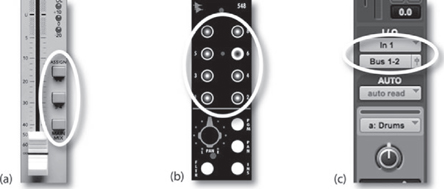
FIGURE 17.25
Channel assignment sections: (a) Onyx 4-bus. (Courtesy of Loud Technologies, Inc., www.mackie.com); (b) API 1608 Console. (Courtesy of Automated Processes, Inc., www.apiaudio.com); (c) ProTools. (Courtesy of Digidesign, a division of Avid Technology, Inc., www.digidesign.com)
Many newer consoles offer only a single button for even- and odd-paired tracks, which can then be individually assigned by using the strip’s main output pan pot. For example, pressing the button marked “5/6” and panning to the left routes the signal only to output bus 5, while panning to the right routes it to bus 6. This simple approach accomplishes two things:
■ Fewer buttons need to be designed into the input strip (lowering production costs and reducing the number of moving parts).
■ Panning instruments within a stereo sound field and then assigning their outputs to a pair of tracks on the multitrack recorder can easily be used to build up a stereo sub-mix.
Of course, the system for assigning a track or channel on a DAW varies with each design, but it’s often straightforward. As always, it’s best to check with the manual, and become familiar with the software before beginning a session.
9 GROUPING
Many DAWs, consoles and professional mixing systems allow any number of input channels to be organized into groups. Such groupings allow the overall relative levels of a series of channels to be interlinked into organized groups according to instrument or scene change type. This important feature makes it possible for multiple instruments to retain their relative level balance while offering control over their overall group level from a single fader or stereo fader pair. Individual group bus faders often have two functions. They can:
■ Vary the overall level of a grouped signal that’s being sent to a recorded track.
■ Vary the overall sub-mix level of a grouped signal that’s being routed to the master mix bus during mixdown.
The obvious advantage to grouping channels is that it makes it possible to avoid the dreaded and unpredictable need to manually change each channel volume individually. Why try to move 20 faders when you can adjust their overall levels from just one? For example, the numerous tracks of a string ensemble and a drum mix could each be varied in relative level by assigning them to their own stereo or surround sound groupings and then moving a single fader—ahhhh, much easier and far more accurate!
It’s important to keep in mind that there are two methods for grouping signals together, when using either a hardware console or a DAW. These can be done by:
■ Signals can be grouped together onto the same, combined audio bus.
■ An external control signal (such as a DC voltage or digital control) can be used to control the relative level of various grouped faders, etc., while keeping the signals separate and discrete.
Using the first method, the grouped signals are physically assigned to the same audio bus, where they are combined into a composite mono, stereo or multi-channel track. Of course, this means that all of your mix decisions have to be made at that time, as all of the signals will be electrically combined together, with little or no recourse for hitting an “‘undo’ button” at a later time. This physical grouping together of channel signals can be easily done by assigning the involved channels in the desired group to their own output bus (Figure 17.26). During mixdown, each instrument group bus will be routed to the main stereo or surround output through the use of pan pots or L/R assignment buttons.
The second grouping system doesn’t combine the signals, but makes use of a single voltage or digital control signal to control the “relative” levels of tracks that are assigned to a group bus. This method (Figure 17.27), allows the signals to be discretely isolated and separated from each other, but their relative levels can be changed in a way that keeps the relative mix balance intact. Quite simply, it’s a way that multiple faders can be either controlled from a single “group fader” or can be ganged together to move in relative tandem with each other.

FIGURE 17.26
Simplified anatomy of the output grouping section on the Mackie Onyx 4-bus analog console, whereby the signals can be combined into a physical group output bus. (Courtesy of Loud Technologies, Inc., www.mackie.com)
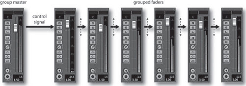
FIGURE 17.27
Tracks can be assigned as a group, so that the relative track levels can change, while keeping the track signals separate in a mix.
As you might have noticed, the above section focused largely upon the idea of a hardware console or mixer. Newer DAWs, on the other hand, now have several options for grouping a signal. Each type has its subtle strengths and should be tried out to see which one works best for you, or in what situation it would work best in.
1. Grouping track: By using a separate group track, the digitally summed grouping signal will be routed through a separate group fader. Controlling this group fader will control the relative volumes of the tracks that are assigned to that group.
2. VCA Grouping: Using this system, the grouped tracks will not be assigned to an assigned output, but will be virtually locked in tandem by a control signal. Moving any fader in that grouping will move the relative volumes of all the faders that are assigned to that group.
3. Using color coding: Here, all of the faders in a grouping can be given a specific track color. Of course, this is not a grouping method at all, however, I mention this as an additional way to easily keep track of a grouped set of tracks.
10 MAIN OUTPUT MIX BUS
The main output bus of an analog console acts to physically or electronically sum (add) the signals from all of the channel fader, pan, effects return and any other signal routing output together into a final mono, stereo or surround audio program output. The output from this audio source can then be processed in a final stage (using compression, limiting or EQ) and then is sent to a master recording device.
In the digital domain, the main output bus likewise serves to digitally combine the sample levels from all of the channel fader, pan, effects return and any other signal routing outputs together into a final mono, stereo or surround digital audio stream that represents the final audio program data stream.
At this stage, the primary concern that needs to be kept in mind is the careful handling of the program’s overall dynamic range. As you might expect, a main output signal that is too low in level could result in increased noise, while excessive output levels will almost certainly result in a distortion. This logic, however, begins to blur when we consider that most of the output signal levels are digital in nature and make use of higher bit-depths. For example, a 24-bit signal could have a dynamic range of up to 144 dB, meaning that the main output could be at lower levels without adding significant noise to the mix. This which would have an added advantage of assuring that the levels will be low enough that digital clipping distortion will not occur—something to be kept on mind, should you know that a mastering engineer will be using their skills to finesse the mix into a final form.
11 MONITOR LEVEL SECTION
Most console, mixing and DAW systems include a central monitor section that controls levels for the various monitoring functions (such as control room level, studio level, headphone levels and talkback). This section (Figure 17.28) often makes it possible to easily switch between multiple speaker sets and can also provide switching between the various inputs, recording device sources and various output formats (e.g., surround, stereo and mono output buses; tape returns; aux send monitoring; solo monitoring).
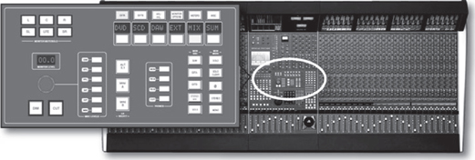
FIGURE 17.28
Monitor level section of the Solid State Logic Duality Console. (Courtesy of Solid State Logic,
www.solid-state-logic.com)
12 PATCH BAY
A patch bay (Figure 17.29) is a panel that’s found in the control room and on larger consoles which contains accessible jacks that correspond to the various inputs and outputs of every access point within a mixer or recording console. Most professional patch bays (also known as patch panels) offer centralized I/O access to most of the recording, effects and monitoring devices or system blocks within the production facility (as well as access points that can be used to connect between different production rooms).

FIGURE 17.29
The patch bay: (a) Ultrapatch PX2000 patch bay. (Courtesy of Behringer International GmbH,
www.behringer.de); (b) rough example of a labeled patch bay layout.
Patch bay systems come in a number of plug and jack types as well as wiring layouts. For example, prefabricated patch bays are available using tip-ring-sleeve (balanced) or tip-sleeve (unbalanced) 1/4-inch phone configurations. These models will often place interconnected jacks at the panel’s front and rear so that studio users can reconfigure the panel simply by rearranging the plugs at the rear access points. Other professional systems using the professional telephone-type (TT or mini Bantam-TT) plugs might require that you hand-wire the connections in order to configure or reconfigure a bay (usually an amazing feat of patience, concentration and stamina).
Patch jacks can be configured in a number of ways to allow for several signal connection options among inputs, outputs and external devices (Figure 17.30):
■ Open: When no plugs are inserted, each I/O connection entering or leaving the panel is independent of the other and has no electrical connection.
■ Half-normaled: When no plugs are inserted, each I/O connection entering the panel is electrically connected (with the input being routed to the output). When a jack is inserted into the top jack, the in/out connection is still left intact, allowing you to tap into the signal path. When a jack is inserted into the bottom jack, the in/out connection is broken, allowing only the inserted signal to pass to the input.
■ Normaled: When no plugs are inserted, each I/O connection entering the panel is electrically connected (with the input routing to the output). When a jack is inserted into the top jack, the in/out connection is broken, allowing the output signal to pass to the cable. When a jack is inserted into the bottom jack, the in/out connection is broken, allowing the input signal to pass through the inserted cable connection.
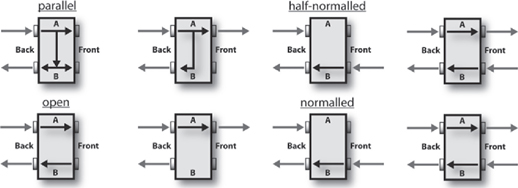
FIGURE 17.30
Typical patch bay signal routing schemes. (Courtesy of Behringer International GmbH, www.behringer.de)
■ Parallel: In this mode, each I/O connection entering the panel is electrically connected (with the input routing to the output). When a jack is inserted into either the top or bottom jack, the in/out connection will still be intact, allowing you to tap into both the signal path’s inputs and outputs.
Breaking a normaled connection allows an engineer to patch different or additional pieces of equipment into a circuit path. For example, a compressor might be temporarily patched between a mic preamp output and an equalizer input. The same preamp/EQ patch point could be used to insert an effect or other device type. These useful access points can also be used to bypass a defective component or to change a signal path order. Versatility is definitely the name of the game here!
13 METERING
The level of a signal’s strength, at an input, output bus and other console level point, is often measured by visual meter display (Figure 17.31). Meter and indicator types will often vary from system to system. For example, banks of readouts that indicate console bus output and tape return levels might use VU metering, peak program meters (PPMs, found in European designs) or digital/software readouts. It’s also not uncommon to find LED overload indicators on an input strip’s preamp, which give quick and easy peak indications as to whether you’ve approached or reached the component’s headroom limits (a sure sign to back off your levels).
The basic rule regarding levels isn’t nearly as rigid as you might think and will often vary depending on whether the device or recording medium is analog or digital. In short, if the signal level is too low, tape, amp and even digital noise could be a problem, because the levels throughout the signal chain might not be optimized. If the level is too high, overloaded preamps, saturated tape or clipped digital converters will often result in a distorted signal. Here are a few rules of thumb:
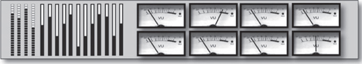
FIGURE 17.31
A set of LED, light-bar and VU meter displays.
■ In analog recording, the proper recording level is achieved when the highest reading on the meter is near the zero level, although levels slightly above or below this might not be a problem, as shown in Figure 17.32. In fact, overdriving some analog devices and tape machines (slightly) will often result in a sound that’s “rough” and “gutsy.”
■ When recording digitally, noise is often less of a practical concern (especially when higher bit depths are used). It’s often a good idea to keep levels at a reasonable level (i.e., peaking at about –12 on the meter), while keeping a respectful distance from the dreaded clip or “over” indicator. Unlike analog, digital is generally unforgiving of signals that are clipped and will generate a grunge sound that’s guaranteed to make you cringe! Because there is no real standard for digital metering levels beyond these guidelines, many feel that giving a headroom margin that’s 12 dB below “0” full scale is usually a wise precaution—especially when recording at a 24-bit or higher depth.
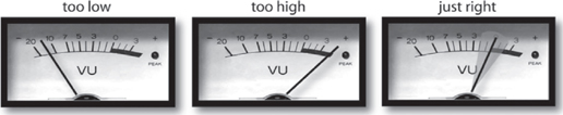
FIGURE 17.32
VU meter readings for analog devices that are too low, too high and just right.
It’s important to keep in mind that recorded distortion isn’t always easy (or possible) to fix. You might not be able to see the peak levels that could distort your sound files, but your ears might hear them after the damage is done. When in doubt, back off and give your levels some breathing room.
The Finer Points of Metering
Amplifiers, magnetic tape and even digital media are limited in the range of signal levels that they can pass without distortion. As a result, audio engineers need a basic standard to help determine whether the signals they’re working with will be stored or transmitted without distortion. The most convenient way to do this is to use a visual level display, such as a meter. Two types of metering ballistics (active response times) are encountered in recording sound to either analog or digital media:
■ Average (rms)
■ Peak
From Chapter 2, we know that the root-mean-square (rms) value was developed to determine a meaningful average level of a waveform over time. Since humans perceive loudness according to a signal’s average value (in a way that doesn’t bear much relationship to a signal’s instantaneous peak level), the displays of many meters will indicate an average signal-level readout. The total amplitude measurement of the positive and negative peak signal levels is called the peak-to-peak value. A readout that measures the maximum amplitude fluctuations of a waveform is a peak-indicating meter.
One could definitely argue that both average and peak readout displays have their own sets of advantages. For example, the ear’s perception of loudness is largely proportional to the rms (average) value of a signal, not its peak value. On the other hand, a peak readout displays the actual amplitude at a particular point in time and not its overall perceived level. For this reason, a peak meter might show readings that are noticeably higher at a particular point in the program than the averaged rms counterpart (Figure 17.33). Such a reading will alert you when short-term peaks are at levels that are above the clipping point, while the average signal is below the maximum limits. Under such conditions (where short-duration peaks are above the distortion limit), you might or might not hear distortion as it often depends on the makeup of the signal that’s being recorded; for example, the clipped peaks of a bass guitar will not be nearly as noticeable as the clipped high-end peaks of a cymbal. The recording medium often plays a part in how a meter display will relate to sonic reality; for example, recording a signal with clipped peaks onto a tube analog tape machine might be barely noticeable (because the tubes and the tape medium act to smooth over these distortions), whereas a DAW or digital recorder might churn out a hash that’s as ugly as the night (or your current session) is long.
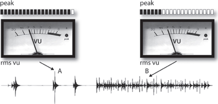
FIGURE 17.33
A peak meter reads higher at point A than at point B, even though the average loudness level is the same.
Getting to the heart of the matter, it goes without saying that, whenever the signal is too high (hot), it’s an indication for you to grab hold of the channel’s mic trim, output fader or whatever level control is the culprit in the chain and turn it down. In doing so, you’ve actually become a dynamic range-changing device. Additionally, the main channel fader (which can be controlling an input level during recording or a tape track’s level during mixdown) is by far the most intuitive and most often used dynamic gain-changing device in the studio.
In practice, the difference between the maximum level that can be handled without incurring distortion and the average operating level of the system is called headroom. Some studio-quality preamplifiers are capable of signal outputs as high as 26 dB above 0 VU and thus are said to have 26 dB of headroom. With regard to analog tape, the 3% distortion level for analog magnetic tape is typically only 8 dB above 0 VU. For this reason, the best recording level for most program material is around 0 VU (although higher levels are possible provided that short-term peak levels aren’t excessively high). In some circumstances (i.e., when using higher bias, low-noise/high-output analog tape), it’s actually possible to record at higher levels without distortion, because the analog tape formulation is capable of handling higher magnetic flux levels. With regard to digital media, the guidelines are often far less precise and will often depend on your currently chosen bit-depth. Since a higher bit-depth (e.g., 24 or 32 bits) directly translates into a wider dynamic range, it’s often a good idea to back off from the maximum level, because noise generally isn’t a problem.
Now that we’ve gotten a few of the basic concepts out of the way, let’s take a brief look at two of the most common meter readout displays.
The VU Meter
The traditional signal-level indicator for analog equipment is the VU meter (see Figure 17.32). The scale chosen for this device is calibrated in “Volume Units” (hence its name) and is designed to display a signal’s average rms level over time. The standard operating level for most consoles, mixers and analog tape machines is considered to be 0 VU. Although VU meters do the job of indicating rms volume levels, they ignore the short-term peaks that can overload a track. This means that the professional console systems must often be designed so that unacceptable distortion doesn’t occur until at least 14 dB above 0 VU. Typical VU meter specifications are listed in Table 17.1.
Since recording is an art form, I have to rise to the defense of those who prefer to record certain instruments (particularly drums and percussion) at levels that bounce or even “pin” VU needles at higher levels than 0 VU. When recording to a professional analog machine, this might actually give a track a “gutsy” feel that can add impact to a performance. This is rarely a good idea when recording instruments that contain high-frequency/high-level signals (such as a snare or cymbals), because the peak transients will probably distort in a way that’s hardly pleasing—and it’s almost never a good idea to overload the meters when recording to a digital system. Always be aware that you can often add distortion to a track at a later time (using any number of ingenious tricks), but you can’t easily remove it from an existing track (software does exist that can help remove some distortion after the fact, but it should never be relied upon). As always, it’s wise to talk such moves over with the producer and artist beforehand.
Table 17.1 VU Meter Specifications
| Characteristic | Specification |
| Sensitivity | Reads 0 VU when fed a +4-dBm signal (1.228 V into a 600-| circuit) |
| Frequency response | ±0.2 dB from 35 Hz to 10 kHz; ±0.5 dB from 25 Hz to 16 kHz |
| Overload capability | Can withstand 5 times 0-VU level (approximately +18 dBm) continuously and 10 times 0-VU level (+24 dBm) for 0.5 sec |
The Average/Peak Meter
While many analog devices display levels using the traditional VU meter, most digital hardware and software devices will often display a combination of VU and peak program-level metering, using an LCD or on-screen readout. This best-of-both-worlds system makes sense in the digital world as it gives us a traditional readout that visually corresponds to what our ears are hearing, while providing a quick-and-easy display of the peak levels at any point in time. Often, the peak readout is frozen in position for a few seconds before resetting to a new level (making it easier to spot the maximum levels), or it can be permanently held at that level until a higher level comes along to bump it up. Of course, should a peak level approach the clipping level, a red “clip” indicator will often light, showing that it’s time to back off the levels.
In recent years, a number of high-quality sound level meters have come onto the market that allow the user to visually inspect the peak, loudness and spectral levels within a recording. These tools can be extremely useful for obtaining the best overall level of a mix, as well as the careful balancing of relative song levels within a project.
Digital Console and DAW Mixer/Controller Technology
In the last decade, console design, signal processing and signal routing technology have undergone a tremendous design revolution with the advent of digital technology. DAWs, digital console and mixers, the iPad and controller design have found their ways into professional, project and audio production facilities at an amazing pace. These systems use large-scale integrated circuits and central processors to convert, process, route and interface to external audio and computer-related devices with relative ease. In addition, this technology makes it possible for many of the costly and potentially faulty discrete switches and level controls that are required for such functions as track selection, gain and EQ to be replaced by a touch controlled system. The big bonus, however, is that since routing and other control functions are digitally encoded, it becomes a simple matter for level, patch and automation settings to be saved into memory for instantaneous recall at any time.
THE VIRTUAL INPUT STRIP
From a functional standpoint, the basic signal flow of a digital console or DAW’s virtual mixing environment is conceptually similar to that of an analog console, in that the input must first be boosted in level by a mic/line pre-amp (where it will then be converted into digital data). From this point, the signals can pass through EQ, dynamics and other signal processing blocks; and various effects and monitor sends, volume, routing and other sections that you might expect, such as main and group output fader controls. From a control standpoint, however, sections of a digital system might be laid out in a manner that looks and feels completely different.
By the very nature of analog strip design, all of the physical controls must be duplicated for each strip along the console. This is the biggest contributing factor to cost and reliability problems in traditional analog design. Since most (if not all) of the functions of a digital console pass through the device’s central processor, this duplication is neither necessary, cost effective or reliable. As a result, designers have often opted to keep the most commonly used controls (such as the pan, solo, mute and channel volume fader) in their traditional input strip position. However, controls such as EQ, input signal processing, effects sends, monitor levels and (possibly) track assignment have been designed into a central, virtual control panel (Figure 17.34) that can be used to focus on and vary a particular channel’s setting parameters. These controls can be quickly and easily assigned to a particular input strip by pressing the “select” button on the relevant input strip channel and then making the necessary changes to that channel.
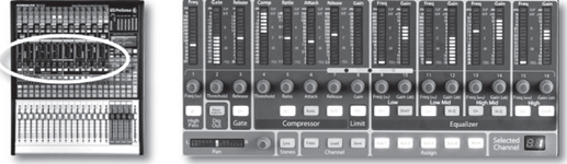
FIGURE 17.34
Presonus StudioLive 16.0.2 Digital mixing console with channel parameter section highlighted. (Courtesy of Presonus Audio Electronics, Inc., www.presonus.com)
In certain digital console, mixer and hardware controller designs, each “virtual input strip” may be fitted with a virtual pot (V-pot) that can be assigned to a particular parameter for instant access. In others, the main parameter panel can be multipurpose in its operation, allowing a number of controls and readouts itself to be reconfigured in a chameleon-like fashion to fit the task at hand. In other cases, touch-screen displays can be used to provide for an infinite degree of user control, while some might use software “soft” buttons that can easily reconfigure the form and function of the various buttons and dial controls in the control panel.
From the above, it’s easy to see that digital consoles and hardware controllers often vary widely in their layout, ease of operation and cost effectiveness. As with any major system device, it’s often a good idea to familiarize yourself with the layout and basic functions before buying or taking on a project that involves such a beastie. As you might expect, operating manuals and basic tutorials are often available on the various manufacturers’ websites.
THE DAW SOFTWARE MIXER SURFACE
Of course, in this new millennium, the vast majority of mixers that exist in the world are software mixers that are integrated into our DAW of choice. With the increased power of the computer-based digital audio workstation, mixing “in the box” has become the norm, rather than the exception.
Through the use of a traditional (and sometimes not-so-traditional) user graphical interface, these mixers offer functional on-screen control over levels, panning, EQ, effects, DSP, mix automation and a host of functions that are simply too long to list here. Often these software mixers (Figure 17.35) emulate their hardware counterparts by offering basic controls (such as fader, solo, mute, select and routing) in the virtual input strip. Likewise, selecting a channel track will assign many of the channel’s functions to a wide range of virtual parameters that can be controlled from a virtual strip or control panel.
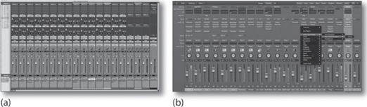
FIGURE 17.35
Example of virtual, on-screen DAW mixers. (a) ProTools. (Courtesy of Avid Technology, Inc., www.avid.com) (b) Logic. (Courtesy of Apple Inc., www.apple.com)
When using a software mixer in conjunction with a DAW’s waveform/edit window on a single monitor screen, it’s easy to feel squeezed by the lack of visual “real estate.” For this reason, many opt for a dual-monitor display arrangement. Whether you are working in a PC or Mac environment, this working arrangement is easier and more cost effective than you might think and the benefits will immediately become evident, no matter what audio, graphics or program environment you’re working on.
When using a DAW controller, the flexibility of the DAW’s software environment can also be combined with the hands-on control and automation of a hardware or iPad-based controller surface (Figure 17.36). More information on the DAW software mixing environment and hardware controllers can be found in Chapter 7.
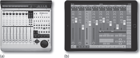
FIGURE 17.36
DAW controllers. (a) Mackie Universal Control. (Courtesy of Loud Technologies, Inc., www.mackie.com) (b) V-Control Pro controller for the iPad. (Courtesy of Neyrinck Audio, www.neyrinck.com)
MIX-DOWN LEVEL AND EFFECTS AUTOMATION
One of the greatest strengths of the digital age is how easily all of the mix and effects parameters can be automated and recalled within a mix. Although many large-scale consoles are capable of automation, computer-based DAW systems are particularly strong in this area, allowing complete control of all parameters throughout all phases of a production. The beauty of being able to set basic levels within a mix or to mix under automation is that a mix can be built up over time, allowing multiple mix versions to be saved, so that we can go back and explore other production avenues or to correct a potential problem. In short, the job of mixing becomes much less of a chore, giving us the time to pursue less of the technology of mixing and more of the art of mixing. What could be bad about that?
Although terminologies and functional offerings will differ from one system to the next, control over the basic automation functions will be carried out in one of two operating modes (Figure 17.37):
■ Write mode
■ Read mode

FIGURE 17.37
Automation mode selections: (a) Pro Tools showing auto selectors within the edit and mixer screens. (Courtesy of Digidesign, a division of Avid Technology, Inc., www.digidesign.com); (b) Cubase/Nuendo showing auto selectors within the edit and mixer screens. (Courtesy of Steinberg Media Technologies GmbH, www.steinberg.net.)
Write Mode
Once the mixdown process has gotten under way, the process of writing the automation data into the system’s memory can begin (actually, that’s not entirely true, because basic mix moves will often begin during the recording or overdub phase). When in the write mode, the system will begin the process of encoding mix moves for the selected channel or channels in real time. This mode is used to record all of the settings and moves that are made on a selected strip or strips (allowing track mixes to be built up individually) or on all of the input strips (in essence, storing all of the mix moves, live and in one pass). The first approach can help us to focus all of our attention on a difficult or particularly important part or passage. Once that channel has been finessed, another channel or group of channels can then be written into the system’s memory—and then another, until an initial mix is built up.
Often, modern automation will let us update previously written automation data by simply grabbing the fader (either on-screen or on the console/controller) and moving it to the newly desired position. Once the updated move has been made, the automation will remain at that level or position until a previously written automation move is initiated, at which point the values will revert to the existing automation settings.
Read Mode
An automated console or DAW that has been placed into the read mode will play the mix information from the system’s automation data, allowing the onscreen and moving faders to follow or match the written mix moves in real time. Once the final mix has been achieved, all you need to do is press play, sit back and listen to the mix.
Drawn (Rubber Band) Automation
In addition to physically moving on-screen and controller faders under read/write automation control, one of the most accurate ways to control various automation parameters on a DAW is through the drawing and editing of on-screen rubber bands. These useful tools offer a simple, graphic form of automation that lets us draw fades and complicated mix automation moves over time.
This user interface is so-named because the graphic lines (that represent the relative fade, volume, pan and other parameters) can be bent, stretched, and contorted like a rubber band (Figure 17.38).

FIGURE 17.38
Automation rubber bands: (a) Pro Tools. (Courtesy of Digidesign, a division of Avid Technology, Inc., www.digidesign.com); (b) Cubase/Nuendo. (Courtesy of Steinberg Media Technologies GmbH, www.steinberg.net)
Commonly, all that’s needed to define a new mix point is to click on a point on the rubber band (at which point a box handle will appear) and drag it to the desired position. You can change a move simply by clicking on an existing handle (or range of handles) and moving it to a new position.
THE FINER POINTS OF MIXING
Once all of the tracks of a project have been recorded, assembled and edited, it’s time to put the above technology to use to mix your tracks into its final media form. The goal of this process is to combine audio, MIDI and effects tracks into a pleasing form that makes use of such traditional tools as:
■ Relative levels
■ Spatial positioning (the physical panned placement of a sound within a stereo or surround field)
■ Equalization (affecting the relative frequency balance of each track)
■ Dynamics processing (altering the dynamic range of a track, group or output bus to optimize levels or to alter the dynamics of a track so it fits better within a mix)
■ Effects processing (the adding of reverb, delay or pitch-related effects to a mix in order to augment or alter the piece in a way that’s natural, unnatural or just plain interesting
Within a well-produced project, sounds can be built up and placed into a sonic stage through the use of natural, psychoacoustic and processed signal cues to create a pleasing, interesting and balanced soundscape. Now, it’s pretty evident that volume can be used to move sound forward and backward within the sound field, and that relative channel levels can be used to position a sound within that field. It’s less obvious that changes in timbre introduced through EQ, delay and reverb can also be used to move sounds within the stereo or surround field. Of course, all of this sounds simple enough; however, the dedication that’s required to hone your skills within this evolving art is what mixing careers are made of.
Before we get started, I’d like to first point you in a direction that just might help your overall mixing technique:
■ It’s often a good idea to create your own “desert island” favorite mix disc or directory—a compilation of several of your favorite songs. By playing these in your mix room, you can get a general idea of how the room sounds. If there’s a problem (particularly, if the room’s new to you), it can help point it out and help you avoid certain pitfalls.
■ Secondly, you might think about inserting a high-resolution frequency-analyzer into the output mix bus. This device (or plug-in) can literally help you see how your mix is “shaping up” and might help pinpoint possible problem areas.
Okay—now let’s take a moment to understand the process better by walking through a fictitious mix. Remember, there’s no right or wrong way to mix as long as you watch your levels along the signal path. Also, there’s no doubt that, over time, you’ll develop your own sense of style.
Mixing and Balancing Basics
1 Let’s begin building the mix by setting the output volumes on each of the instruments to a level that’s acceptable to your main mixer or console. From a practical standpoint, (if a basic mix wasn’t built during the production phase) you might want to start with all of the faders down. You can then start to bring the basic tracks up one at a time, until a desirable blend begins to take shape. You could also take an entirely different approach by setting them all at unity gain.
2 The next step is to repeatedly listen to the project as it begins to take shape, making any fader and pan changes that are necessary until it begins to take shape. If there is a vocal track, it could be brought into the mix at this time to see how the overall blend works, or you could work on the instrument tracks and bring the vocal track in later. In any case, the idea is to begin the process of shaping the mix in a way that sounds pleasing and reinforces the song’s musical style and intentions.
3 EQ can be applied to any problematic track that doesn’t quite sound good or fit into the mix properly. A general consensus on EQ is that it’s often best to equalize a track within the context to the mix (i.e., not by listening to the lone, soloed track), however, if a problem track does arise, try listening to the offending instrument on its own, making any corrections and then listening to how the corrections fit into the mix.
REMEMBER:
It’s always wise to save your individual mixes under a new and identifiable name. You never know when you might want to revert to a previous mix version. Creating a “mixback” directory within the song’s session directory lets you throw the previous mix versions (project_bitsamplerates_mixname_001, etc.) into it without having dozens of previous version numbers clutter things up in your song directory.
Another approach to sound-shaping using EQ is called “carving.” This approach uses EQ to restrict frequencies that are present on a track, so they don’t conflict with other important instrument tracks that exist in the same range. For example, a synth track that has a great deal of additional low-frequency energy, might be rolled-off at the low-end, so that it doesn’t “muddy” up the low end and/or conflict with the other bass instruments.
As with all things sound, letting your ears be your EQ guide takes time and experience—be patient with yourself.
4 Should the mix need to be changed at any point from its initial settings, you might turn the automation on for that track and begin building up the mix. You might also want to save your mix at various stages of its development under a different name songname01, songname02, 02mybestmix, 03jimsnew approach, etc. (personally, I save these versions within the project’s directory as songname_mixbacks). Saving previous versions never hurts, as it makes it easier to return to the point, should you make a mistake or simply need to take a step back in time.
5 You might want to group various instrumental sections together within the mix (Figure 17.39). The time savings of this process really can’t be overstated. For example, by grouping instrument types together, you can:
■ Reduce the volume on several tracks by simply grabbing a single fader instead of moving each track individually.
■ When a session contains lots of tracks, soloing the group tracks can help you find a track much more quickly than searching through the tracks— it really does!
■ Effects can be quickly and easily added to an instrument section at the group level (either as an insert or as a send).

FIGURE 17.39
Figure showing the group master (at left, entitled “main”) is used to control the grouping (at right, which is assigned to “main”).
6 Just as reverb, delay and other time-based effects can be added to the mix, should you wish to add a bit of controlled “grit” or “dirt” to a mix, an effects send could be set up to add a degree of compression, tape emulation saturation or whatever you might want to add to the mix. Once set up, this dirt, glue or whatever you want to call it can be tastefully added to a single channel or grouped set of tracks by mixing it in at the send level. The same goes for room ambience as a room simulation plug-in (or actual mics in the studio) can be entered into the mix at the send level to add a degree of openness and acoustic realism to the mix.
7 When the mix comes together, you can then begin to think about inserting some form of EQ and/or dynamics processing to the master channel output bus. This is not a “required” stage in the process, simply an additional tool that can be used to shape the overall sound of your mix. Of course, this subject starts many a barroom brawl amongst recording and mastering engineers alike. Adding too much compression to a mix can take the life out of your recording, while adding just the right amount can help tame the mix’s overall levels. Likewise, bad EQ decisions at the mix bus stage can wreck a mix like a barrel of monkeys. Applying too much EQ to the master bus means that other problems in your mix might exist—not to mention the fact that most mastering engineers would prefer that you leave the final processing to them. All of these are valid comments that should be kept in mind, but in the end it’s your mix.
8 This calls to mind a very important aspect of most types of production (actually it’s a basic tenant in life): Keep it simple! If there’s a trick you can use to make your project go more smoothly, use it.
9 Once you’re happy with your basic mix, you might want to export it as a file to play in your car, in a friend’s studio, put it in your best/worst boom box and/or have your friends critique it. Take notes and then revisit the mix after a day. You might want to take the time to compare your new mix to your desert island disc, to hear how it stacks up against your favorite (or the producer’s favorite) mixes. Good or bad, it’ll be a learning (and possibly humbling) experience.
A FINAL FOOTNOTE ON THE ART OF MIXING
Actually, the topic of the art of mixing could easily fill a book (and I’m sure it has); however, I’d simply like to point out the fact that it is indeed an art form, and as such is a very personal process. I remember the first time I sat down at a console (an older Neve 1604). I was truly petrified and at a loss as to how to approach the making of my first mix. Am I over-equalizing? Does it sound right? Will I ever get used to this sea of knobs? Well, folks, as with all things—the answers come to you when you simply sit down and mix, mix, mix! It’s always a good idea to watch others in the process of practicing their art and take the time to listen to the work of others (both the known and the not-so-well known). With practice, it’s a foregone conclusion that you’ll begin to develop your own sense of the art and style of mixing, which, after all, is what it’s all about. It’s all up to you now. Just dive into the deep end—and have fun!