
2
Liquid‐Phase Interfacial Synthesis of Highly Oriented Crystalline Molecular Nanosheets
Rie Makiura
Osaka Prefecture University, Department of Materials Science, Osaka, 599‐8570, Japan
2.1 Introduction
Over the past decade, significant progress has been made in the field of functional molecular‐based materials, resulting in an increased understanding of the relationship between molecular structure/ordering and performance in various applications in diverse fields such as electronics, energy creation/storage, and biomaterials. For most potential applications, organizing organic molecules into two‐dimensional (2D) thin film state is necessary. In order to create thin films with organic molecules, two experimental approaches have been followed: gas‐phase and liquid‐phase protocols [1]. Representative gas‐phase processes include vacuum deposition, sputtering, and molecular beam epitaxy. In these methods, molecules are directly deposited on the substrate surface during the fabrication procedure. For liquid‐phase processes, fabrication techniques are further divided into two categories – with or without solid substrates. Representative methods, which include deposition on solid substrates, are dip casting, drop casting, and spin casting, whereas in the absence of solid substrates, the methods employed utilize gas/liquid or liquid/liquid interfaces. In this chapter, we focus primarily on the formation of highly crystalline molecular nanosheets at such liquid interfaces. Compared with the direct deposition methods on solid substrates, nanosheets formed on liquid surfaces can be transferred to various types of substrates, thereby increasing the options for potential applications. Especially, we discuss the assembly of new types of crystalline nanosheets – metal–organic framework (MOF) nanosheets – rationally built using molecular components, which do not contain alkyl chains and can be connected via coordination bonds with metal ions in a directionally controllable manner (Figure 2.1).
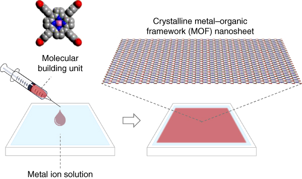
Figure 2.1 Schematic illustration of the assembly of crystalline metal–organic framework (MOF) nanosheets at the air/liquid interface.
2.2 Molecular Nanosheet Formation with Traditional Surfactants at Air/Liquid Interfaces
2.2.1 History of Langmuir–Blodgett Film
Langmuir–Blodgett (LB) film is the most well‐known molecular thin film formed at the gas/liquid interface. History of LB film begins in 1774 [2]. Benjamin Franklin observed that when he dropped a teaspoon of oil in a pond, waves became calmer and almost flat like a mirror over several square yards. Almost a century later, Lord Rayleigh considered the report by Franklin and provided an explanation of the phenomenon involved – oil is composed of oleic acids, which spread evenly on the water surface. Rayleigh evaluated the thickness of the thin film to be less than 2 nm from the mount of spread oil. Around the same time, Agnes Pockels had accomplished an analysis of monolayer formation at gas/liquid interfaces. She was interested in oil dirt spread on sink water and created a primitive instrument for measuring surface pressure. Her letter on the observations to Rayleigh was elaborated with Rayleigh's help and published in Nature in 1891 and 1892 [3, 4]. Inspired by Pockels' work, Irving Langmuir developed the Langmuir trough and conducted systematic works on monolayers assembled at air/liquid interfaces [5]. Langmuir discovered together with Katherine Blodgett that the spread organic layer can be uniformly deposited on a solid substrate by insertion of the substrate vertically into the water subphase [6]. In accord with the history of the discoveries, the name “Langmuir film” refers to a monolayer floating on the liquid surface, while a “LB film” represents a multistacked film deposited on a substrate by the repetitive process of substrate immersion/lift‐up into/from the liquid subphase.
2.2.2 Basics of Molecular Nanosheet Formation at Air/Liquid Interfaces
Typical organic molecules used for monolayer creation at air/liquid interfaces are surfactants containing both hydrophobic and hydrophilic parts [2]. The hydrophobic parts are mainly hydrocarbon or fluorocarbon chains, whereas the hydrophilic parts are polar groups such as −COOH, −OH, and −NH2. Formation of monolayer at the air/liquid interface depends on (i) miscibility between polar groups and subphase (commonly water), (ii) van der Waals interactions between hydrophobic parts, and (iii) relative importance of factors (i) and (ii).
Amphiphilic surfactant molecules are dissolved in highly volatile organic solvents such as hexane and chloroform and the solution is dropped onto the water surface. As soon as the droplets reach the water surface, they spread over the surface and insoluble monolayers form at the interface between air and liquid. The surfactant molecules arrange themselves in such a way so that their hydrophilic parts are down into the water subphase and the hydrophobic parts stay on the air side. The monolayer formed at the air/liquid interface is called a Langmuir film or L film.
In this chapter, we use the term “nanosheet” to refer both thin films floating on liquid surfaces and free‐standing films. Therefore, nanosheets necessarily include Langmuir films. Following the LB film history, however, we use the term “Langmuir film” only for monolayers composed of surfactants with long hydrocarbon chains.
2.3 Application of Functional Organic Molecules for Nanosheet Formation at Air/Liquid Interfaces
2.3.1 Functional Organic Molecules with Long Alkyl Chains
Following the initial discovery of the LB method, components are no longer restricted to simple surfactants and various types of molecules have been utilized for creating functional thin films at the air/liquid interface. Fujihira et al. reported an electrochemical photodiode fabricated by depositing complex LB films, which consisted of an electron acceptor, a sensitizer, and an electron donor surfactant derivative [7]. The organization of an amphiphilic azobenzene derivative in monolayers at the air/water interface is strongly controlled by association phenomena due to intermolecular interactions of the azobenzene moiety [8, 9]. Ariga et al. discussed progress in hydrogen‐bond‐based molecular recognition at the air/water interface [10]. Nonetheless, all the molecules reported in these works incorporate long alkyl chains, a feature that sometimes restricts potential functionalities because of the associated highly insulating behavior.
2.3.2 Functional Organic Molecules without Long Alkyl Chains
Application of the LB method to functional molecules without any alkyl chain has also been reported. Floating layers of C60 at the air/water interface were first observed by Obeng et al. [11] Mixed Langmuir films of C60 with icosanoic acid were then reported by Nakamura et al. [12]. After that, the lattice image of C60 films prepared on the pure water subphase was shown [13]. A high‐performance photo‐responsive molecular field‐effect transistor was formed from Langmuir monolayers of copper phthalocyanine (CuPc) [14]. High carrier mobility and low threshold voltage for both holes and electrons in an organic field‐effect transistor were realized with ordered layers composed of a europium triple‐decker complex assembled at the air/liquid interface [15]. In most cases where functional molecules without alkyl chains are used, the molecules pack in the layered structure at the air/liquid interface via weak interactions such as van der Waals and π–π interactions. On the other hand, much stronger interactions including covalent, coordination, and multiple hydrogen bonds can lead to layers with increased stability, and molecular arrangements can be more finely controlled by applying such directly guided interactions. Schlüter and King groups reported the synthesis of a large area nanoporous two‐dimensional polymer at the air/liquid interface [16]. Compression followed by photopolymerization at the interface provides organic nanosheets in which the molecular building units are covalently connected with their long‐range structural order confirmed by scanning tunneling microscopy.
In this chapter, we focus on nanosheets formed via coordination bonds between metal ions and organic ligands, so‐called MOFs or porous coordination polymers (PCPs), for their rich variety of materials design, as described in Section 2.4. Especially, we discuss the progress in the assembly of MOF nanosheets composed of porphyrins at the air/liquid interface. Porphyrins are important functional molecules, which have generated significant research interest from the viewpoint of topological design of ordered networks as well as for their rich chemical/physical properties without long alkyl chains.
2.3.3 Application of Functional Porphyrins on Metal Ion Solutions
Porphyrins and metalloporphyrins are very stable π‐conjugated macrocyclic molecules with square‐planar geometry. As such, they are highly suitable building components for the formation of 2D supramolecular architectures. There is a large family of porphyrins and metalloporphyrins with or without incorporation of different center‐occupying metal ions and with a rich variety of peripheral functional substituents, such as alkyl chains, (hetero)aromatic groups, hydroxy groups, carboxylic acid, and amino groups [17–23]. Combination of a hydrophobic macrocyclic core and peripheral polar substituents in porphyrins allows us to apply them to air/liquid interfacial synthesis for nanosheet formation. Qian et al. employed the functional porphyrin, 5,10,15,20‐tetrakis(4‐pyridyl)‐21H,23H‐porphyrin (H2TPyP), and its metal–ion derivatives (MTPyP, M = ZnII, MnIII, TiIVO) on palladium salt aqueous solutions [24–29]. Drawing from the structural results on bulk crystals synthesized in solution of Drain et al., they conjectured that a similar check‐patterned structure was also formed in their films by coordination of Pd2+ ions and the peripheral pyridine units in the porphyrin building blocks [30–32]. However, no direct experimental evidence for such structure formation in the films was provided.
2.4 Porphyrin‐Based Metal–Organic Framework (MOF) Nanosheet Crystals Assembled at Air/Liquid Interfaces
2.4.1 Metal–Organic Frameworks
The current explosion of interest in new MOFs, PCPs, or related porous hybrid solids arising from the virtually unlimited structural possibilities involving combinations of inorganic and organic building components has implications for general fundamental crystal growth techniques and for a number of potential applications ranging from the materials science to life science fields [33–37]. In many cases of targeted synthesis of polycrystalline or single crystalline bulk MOFs using solvothermal reactions, the desired structures that possessed well‐defined pores were generated following rational molecular design routes, strategic choice of combination of molecular components based on coordination chemistry knowledge, and exploration of the reaction conditions. On the other hand, controlling the size of porous objects at the nanoscale and arranging such objects on/with various substances in certain desired ways (e.g. sequentially layered on top of each other, patterned on surfaces) remains as a challenge that needs to be addressed. In addition, understanding the roles of nanoscale size and interfacial conditions in integrated systems in defining the properties of such porous solids can lead to optimization of their potential functionalities.
In fact, reports on various attempts to process bulk polycrystalline MOFs and to fabricate nanoscaled ones by developing new methodologies such as microwave synthesis, inverse emulsion technique, and liquid‐phase epitaxy have been increasing in recent years [38–48]. Especially, 2D sheet assemblies are necessary when considering the use of such coordination materials, which frequently incorporate functional π‐electron components, in nanotechnological thin film devices.
2.4.2 Method of MOF Nanosheet Creation at Air/Liquid Interfaces
We have recently succeeded to create highly crystalline nanosheets with a porphyrin derivative at the air/liquid interface. In our first report on porphyrin nanosheet creation, we used 5,10,15,20‐tetrakis(4‐carboxyphenyl)‐porphyrinato‐cobalt(II) (CoTCPP) and a copper (II) ion aqueous solution as a subphase (NAFS‐1) [49]. At that time, we established the nanosheet structure only after multiple transfer/deposition processes of the nanosheets formed at the air/liquid interface onto a solid substrate [49–51]. In subsequent work, we were able to follow the nanosheet formation directly by in situ synchrotron X‐ray diffraction (XRD) at the air/liquid interface [52]. Therefore, here we start by considering the creation of the porphyrin nanosheet, NAFS‐13, that was followed by in situ XRD measurements. In this work, we used 5,10,15,20‐tetrakis(4‐carboxyphenyl)‐porphyrinato‐palladium(II) (PdTCPP) as a building unit (Figure 2.2, left top). The procedure for preparing crystalline nanosheets was initiated with the spreading of the PdTCPP solution onto Cu(NO3)2·3H2O aqueous solution (Figure 2.2, bottom). The formation of the NAFS‐13 nanosheets where PdTCPP units were connected into a 2D nano‐architecture via copper bridging ions was monitored by measuring the surface pressure – mean molecular area (π − A) isotherm. The surface pressure was increased to 40 mN m−1 by compression with the barrier walls of the trough that moved at a constant speed. When the same PdTCPP solution was spread onto a purified water subphase without any metal ions in the Langmuir trough and compressed at the same barrier speed, the mean molecular area, A, recorded at the same surface pressure was significantly smaller (Figure 2.2, right top). This implies that the PdTCPP units stand vertically at some angle to the liquid surface (Figure 2.3, left top) or remain in the horizontal orientation but pack very closely (Figure 2.3, left bottom). In contrast, when copper ion solution is used, they lie flat on the solution surface as a result of the coordinative linking of copper ions with the tetratopic PdTCPP molecules (Figure 2.3, right). The nanosheets were transferred from the liquid subphase to a quartz substrate, and ultraviolet–visible (UV–Vis) absorption spectroscopic measurements were conducted. The absorbance of the Soret band of PdTCPP in nanosheets fabricated on purified water is larger than that of NAFS‐13 nanosheets formed on copper ion aqueous solution (Figure 2.4). This is consistent with a larger number of PdTCPP units packing in the same area of the monolayer in agreement with the (π − A) isotherm measurements (Figure 2.2, right top).
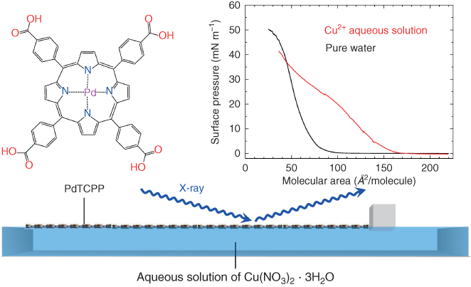
Figure 2.2 Formation of NAFS‐13 (PdTCPP‐Cu nanosheet) was monitored by in situ grazing incident XRD measurements. The solution of PdTCPP molecular building units is spread onto the copper ion aqueous solution in a Langmuir trough. The surface pressure, π, is controlled by the movement of a single barrier and is kept constant during the collection of each GIXRD profile at the air/liquid interface. The right top figure shows surface pressure – mean molecular area (π − A) isotherms for NAFS‐13 (red) and for PdTCPP solution spread onto pure water subphase (black).
Source: From Makiura and Konovalov 2013 [52]. Reproduced with permission of Nature Publishing Group.

Figure 2.3 Proposed molecular arrangements of PdTCPP nanosheets in two different subphases as deduced by concentration of the molecular areas derived by the π − A isotherms.
Source: From Makiura and Kitagawa 2010 [50]. Reproduced with permission of John Wiley and Sons.

Figure 2.4 UV–Vis absorption spectra for PdTCPP nanosheets (monolayer) fabricated on copper ion solution (NAFS‐13, red solid line) or pure water (black solid line) subphase.
2.4.3 Study of the Formation Process of MOF Nanosheets by In SituX‐Ray Diffraction and Brewster Angle Microscopy at Air/Liquid Interfaces
Detailed insights into the formation of the NAFS‐13 nanosheets were obtained by in situ synchrotron XRD measurements [52]. These were conducted directly at the air/liquid interface in grazing incidence (GI) mode with the incident X‐ray beam almost parallel to the liquid surface, as illustrated in Figure 2.2. Figure 2.5a shows the evolution of the in‐plane grazing incidence X‐ray diffraction (GIXRD) profiles measured for NAFS‐13 with increasing surface pressure. Many sharp Bragg peaks were observed, providing the signature of the formation of a highly crystalline organization. Importantly, such a profile with many sharp peaks was seen at the low surface pressure point (π ≈ 0) after spreading the PdTCPP solution onto the copper ion solution. The result suggests that the formation of NAFS‐13 with long‐range order occurs in a self‐assembling manner without the need for surface compression. The assemblies were induced by the interfacial reaction between the peripheral carboxylic acid groups of the PdTCPP molecules and the copper ions in the subphase.

Figure 2.5 In situ grazing incidence in‐plane synchrotron X‐ray diffraction patterns collected at the air/liquid interface for NAFS‐13 nanosheets. (a) Observed GIXRD (λ = 1.549 Å, incidence angle, α = 0.12°) profiles at surface pressures, π = 0, 1, 5, 10, 20, and 30 mN m−1. (b) Basal plane projection of the crystalline structure of NAFS‐13, which consists of a 2D “checkerboard” motif of PdTCPP units linked by binuclear Cu2(COO)4 paddle wheels. (c) Schematic diagram of the crystalline structure of NAFS‐13, which consists of 2D sheets of thickness ∼3 Å viewed along the b axis. (d–g) Evolution of the crystalline structure and morphology of the molecularly thin NAFS‐13 nanofilms with change in surface compression. (d) Surface pressure – mean molecular area (π − A) isotherm. (e) Unit cell basal plane dimension, a. (f) Average crystalline sheet domain size estimated from the full width at half maximum of the intense (110) Bragg reflection. (g) Relative intensity of the (110) reflection normalized to the value at the highest surface compression versus mean molecular area.
Source: From Makiura and Konovalov 2013 [52]. Reproduced with permission of Nature Publishing Group.
A homologous series of porphyrin‐based bulk crystalline MOFs (porphyrin paddle‐wheel frameworks, PPFs) has been reported [53–56]. Stacking sequences were controlled by utilizing different metal‐centered porphyrins, MTCPP (M = Co(III), Zn(II), Pd(II)), in which the coordination number of the central metal site was varied between six (octahedral, Co(III)), five (square‐pyramidal, Zn(II)), and four (square‐planner, Pd(II)), whereas the in‐plane linkage and the checkerboard pattern remained identical for all the three crystalline materials. Returning to the NAFS‐13 nanosheets, we find that all observed Bragg peaks in their GIXRD profile index as (hk0), as shown in Figure 2.5a. They correspond to a 2D square unit cell with lattice parameters, a = b ≈ 16.6 Å. The lattice metrics are extremely close to those of the bulk crystalline analogues composed of MTCPP porphyrin building units [53–56]. The comparable lattice sizes unambiguously confirm that the molecular arrangement parallel to the sheet plane in NAFS‐13 is that of PdTCPP molecules and dimeric paddle‐wheel Cu2(COO)4 secondary building units, which adopt a checkerboard structural motif (Figure 2.5b and c). The diffraction profile comprising more sharp peaks does not change as the surface pressure is progressively increased, implying that the molecular arrangement of the NAFS‐13 nanosheet remains intact upon the surface compression. On the other hand, the peak width and intensity of the Bragg reflections gradually change with surface compression (Figure 2.5d–g). In the low surface pressure region (π = 0–1 mN m−1), the unit cell size of the square lattice and the average crystalline domain size of the NAFS‐13 nanosheets do not change, indicating that surface compression has little influence on the sheet formation process. On the other hand, the peak intensity increases sharply with the surface compression in the same surface pressure range. These results suggest that the effect of surface compression is first to increase the surface coverage by gathering the preassembled NAFS‐13 nanosheet domains to a smaller area without affecting the crystalline domain size. This interpretation was also supported by the growth in the intensity of the Soret band of PdTCPP with increasing surface pressure observed by UV–Vis spectroscopy for NAFS‐13 formed at different surface pressure points and transferred onto quartz substrates (Figure 2.6).

Figure 2.6 UV–Vis absorption spectra for NAFS‐13 nanosheets. The films formed at a surface pressure of 1, 10, and 20 mN m−1 were deposited onto quartz substrates and the spectra were measured after a rinsing/solvent immersion/drying process.
However, further compression of the surface influences in a pronounced way both the crystalline structure and the morphology of the nanosheets. Firstly, the in‐plane lattice parameter, a, decreases monotonically as π increases (Figure 2.5e). This is accompanied by a contraction in the nanosheet domain size and a continuous growth of the intensity of the (110) Bragg reflection (Figure 2.5f). In order to understand this, we recall that as the surface pressure increases, the coverage of the surface increases until it is fully occupied by the NAFS‐13 nanosheets. Upon further compression, the nanosheets gather into a smaller area until their peripheral parts start to squeeze neighboring sheets, thereby leading to increased surface roughness through deformation or multiple sheet stacking. The assembling process of NAFS‐13 at the air/liquid interface is schematically illustrated in Figure 2.7. Brewster angle microscopy (BAM) measurements support this phenomenological interpretation (Figure 2.8). The BAM images show first a progressive increase of surface coverage by the nanosheets upon compression, followed by the appearance of cracks and surface deformation at high surface pressure points. In addition, white spots are observed in the BAM images regardless of the surface pressure, implying the existence of molecular aggregation in the nanosheets.
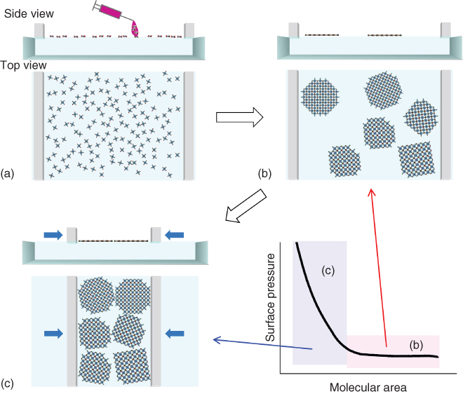
Figure 2.7 Schematic illustration of the assembling processes of the NAFS‐13 nanosheets at the air/liquid interface. Spreading molecular components PdTCPP on the copper ion aqueous solution subphase (a) drives immediate formation of 2D arrays where PdTCPP molecules are highly ordered because of the coordinative interaction between their carboxylic parts and copper ions. (b) The 2D domain arrays are distributed inhomogeneously when the surface area is relatively large in comparison with the number of spread molecules – the low surface pressure condition. (c) Further pressing of the surface gathers the 2D arrays to a smaller area, resulting in the high coverage of the sheets after deposition onto the solid substrates and the size of the crystalline domains becomes smaller by squeezing neighboring domains each other.
Source: From Makiura et al. 2011 [51]. Reproduced with permission of Royal Society of Chemistry.

Figure 2.8 Brewster angle microscopy (BAM) images of the NAFS‐13 nanosheet at the air/water interface captured during compression. (a) Surface of the aqueous Cu2+ ion aqueous solution subphase before spreading PdTCPP molecules, (b) at 0 mN m−1, after spreading PdTCPP molecules, (c) at 1 mN m−1, (d) at 5 mN m−1, (e) at 10 mN m−1, (f) at 20 mN m−1, (g) at 33 mN m−1, and (h) at 40 mN m−1.
2.4.4 Application of a Postinjection Method Leading to Enlargement of the Uniform MOF Nanosheet Domain Size
The in situ XRD measurements at the air/liquid interface on the NAFS‐13 nanosheet together with the complementary BAM measurements have established that the important process in the nanosheet creation procedure is the interfacial coordination reaction, which occurs immediately after spreading the molecular building unit solution onto the subphase containing metal ions [52]. Therefore, this is the most critical step in determining the sheet domain size. However, it is unavoidable that droplets of the spread solution produce surface ripples in the conventional protocol of the nanosheet creation at the air/liquid interface. By recalling the procedure for obtaining large single crystals of coordination compounds with slow diffusion protocols of reactant solutions, we have attempted to integrate comparable diffusion protocols into the nanosheet growth strategy. As illustrated in Figure 2.9, we first spread the solution of the molecular building units of PdTCPP on the purified water subphase and then gently inject the concentrated copper ion aqueous solution into the subphase from the corner of the Langmuir trough.
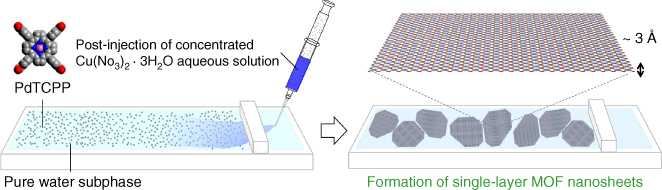
Figure 2.9 Schematic illustration of the postinjection methodology employed in the fabrication of NAFS‐13 nanosheets. A PdTCPP solution is first spread directly on the pure water subphase. A concentrated copper ion aqueous solution is then slowly injected into the water subphase from the side surface, which is separated from the Langmuir trough by the compression barrier.
Source: From Makiura and Konovalov 2013 [52]. Reproduced with permission of Nature Publishing Group.
After spreading the PdTCPP solution but before the injection of the copper ion solution, the in‐plane XRD pattern observed at the air/liquid interface does not contain any Bragg peaks (Figure 2.10 black). This confirms that the PdTCPP molecules do not self‐assemble to form a crystalline nanosheet in the absence of copper ions. After injection of the concentrated copper ion solution into the purified water subphase, more number of very sharp peaks appear in the GI in‐plane XRD profile (Figure 2.10 red). The positions of the observed Bragg peaks coincide with those recorded for the NAFS‐13 nanosheet formed by our conventional method – the PdTCPP solution is spread on the copper ion solution subphase (Figure 2.10 inset). This confirms the formation of the nanosheets with the same crystalline structure and identical lattice constants. However, the peak widths of the Bragg peaks in the GI in‐plane XRD pattern of the nanosheet formed by the postinjection method are considerably smaller than those observed for the nanosheet by the conventional method. This implies a significant increase in the lateral size of crystalline domains in the nanosheets.

Figure 2.10 Observed grazing incidence in‐plane synchrotron GIXRD profiles (λ = 1.549 Å, incidence angle, α = 0.12°) for PdTCPP spread on the pure water subphase before (black line) and after (red line) injection of the copper ion aqueous solution in the absence of barrier compression. The inset shows a comparison of the in‐plane GIXRD profiles for the NAFS‐13 nanosheets formed by the conventional method of Figure 2.2 (blue line) and the postinjection method (red line) at π = 0 mN m−1.
Source: From Makiura and Konovalov 2013 [52]. Reproduced with permission of Nature Publishing Group.
In addition, the recorded BAM images of the NAFS‐13 nanosheets formed by the postinjection method reveal much smoother surface morphology than that of those assembled by the conventional method (Figure 2.11). Furthermore, white spots associated with the presence of molecular aggregations are now completely absent. Therefore, surface rippling and instant reaction between the spread molecular building units and copper ions from the subphase both limit nanosheet domain growth and lead to the creation of molecular aggregates restricting the formation of smooth uniform nanosheets. On the other hand, the postinjection method, which effectively realizes gentle interfacial reaction under slow diffusion condition, leads to the enlargement of the sheet domain size and provides smooth surface morphology of the monomolecularly thin nanosheets.

Figure 2.11 Brewster angle microscopy (BAM) images taken during the formation of the NAFS‐13 nanofilms fabricated by the postinjection (a and b) and the conventional (c and d) methods at compressions, π = 0 and 20 mN m−1.
Source: From Makiura and Konovalov 2013 [52]. Reproduced with permission of Nature Publishing Group.
We also successfully achieved further increase of the domain size of the nanosheet by changing the molecular building unit to 5,10,15,20‐tetra(4‐pyridyl)‐porphyrinato‐zinc (II) (ZnTPyP), while keeping the same subphase with copper ions (Figure 2.12) [57]. The MOF nanosheets (NAFS‐21) composed of ZnTPyP are of monomolecular thickness with a crystalline domain size in the direction parallel to the liquid surface of submicron scale, larger than 410 nm – as the XRD peak widths were limited by the resolution of the synchrotron XRD experimental setup, the precise sheet size is expected to be larger approaching the micrometer size. We consider that the change of the molecular building units from anionic MTCPP to neutral ZnTPyP slows down the interfacial coordination reaction with the copper ions, leading to the formation of large nanosheet domains without the need to apply the postinjection method.
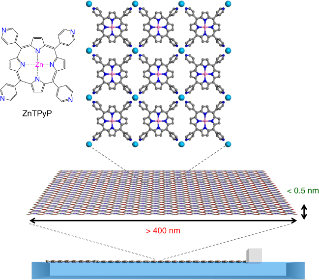
Figure 2.12 Schematic illustration of the assembly of the ZnTPyP‐Cu nanosheets (NAFS‐21) at the air/liquid interface.
2.4.5 Layer‐by‐Layer Sequential Growth of Nanosheets – Toward Three‐Dimensionally Stacked Crystalline MOF Thin Films
Layer‐by‐layer (LbL) deposition is a representative technique of thin film growth and the notation LbL has usually been applied to describe alternate adsorption of electrostatically charged polymers or colloids [58, 59]. Nowadays, the term LbL is widely used to describe various stepwise bottom‐up protocols of thin film growth [60–64]. Typically, two solutions consisting of different components are prepared and a solid substrate is immersed into the solutions in an alternating manner.
Focusing on the coordinative reaction between metal ions and organic ligands, such LbL protocols have been widely used to grow supramolecular networks on solid surfaces [65–68]. However, the LbL method was used for the fabrication of thin films of MOFs with high crystallinity only 10 years ago [69–75]. Shekhah et al. reported a step‐by‐step route of the synthesis of crystalline MOFs for understanding the MOF formation process in a rational way rather than to fabricate MOF thin films [70, 71]. Although the reports show promising results in obtaining partially ordered systems or with some ordering preference, the assembly of MOF thin films with completely controlled size and growth direction was not achieved, and the structural details, especially in the molecular arrangement parallel to the substrate surface, remain unknown.
A distinct advantage of the LbL growth mode is that it provides good control of the film orientation and the number of layers in the vertical direction to the substrate (out‐of‐plane). However, comparable control is not built into the technique for the horizontal direction parallel to the substrate surface (in‐plane). This key aspect was addressed by the incorporation of the air/liquid interface into the film growth methodology allowing exquisite control in both lateral and transverse directions for the first time. Application of the air/liquid interfacial reaction mentioned above together with the LbL protocol can be integrated in a modular manner to fabricate perfectly crystalline MOF thin films on a solid surface under mild conditions. Here, we describe the formation of a porphyrin‐based MOF thin film (NAFS‐2) endowed with highly crystalline order both in the out‐of‐plane and in‐plane orientations to the substrates by applying the combination of the air/liquid interfacial reaction and the LbL growth [76].
The NAFS‐2 nanosheet composed of 5,10,15,20‐tetrakis(4‐carboxyphenyl) porphyrin (H2TCPP) formed on the copper ion aqueous solution was transferred to the solid substrate by the horizontal dipping method (the substrate surface is parallel to the subphase surface) (Figure 2.13). Excess copper ions were removed by following immersion of the substrate into purified water. To stack further layers, the substrate with the predeposited NAFS‐2 nanosheet was again dipped on the subphase surface. The number of the layers deposited is precisely controlled by the number of cycles of sheet transfer. The successive LbL growth of the NAFS‐2 nanosheet was monitored by UV–Vis spectroscopy. The linear increase in absorbance of the H2TCPP Soret band indicates that roughly the same amount of H2TCPP molecules is deposited in each step of the layer stacking protocol (Figure 2.14a and b). Similarly, a linear increase in the IR absorbance attributed to the COO symmetric stretch band of NAFS‐2 with increasing number of cycles was also confirmed (Figure 2.14c and d). This further supports that to a good approximation, each cycle leads to the transfer of the same amount of H2TCPP molecules. The XRD profile measured in out‐of‐plane scans shows two peaks, which can be indexed as (001) and (003). This reveals that NAFS‐2 has a highly ordered growth perpendicular to the film growth direction. The value of the interlayer spacing was estimated to be 7.026 Å from the Bragg reflection positions. Detailed explanations of the structure will be described in the next section.
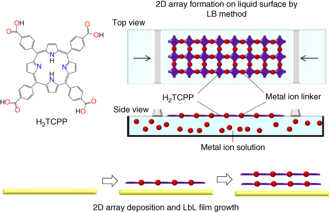
Figure 2.13 Schematic illustration of the assembly process of the H2TCPP‐Cu nanosheets (NAFS‐2) at the air/liquid interface and their layer‐by‐layer (LbL) growth.
Source: From Motoyama et al. 2011 [76]. Reproduced with permission of American Chemical Society.
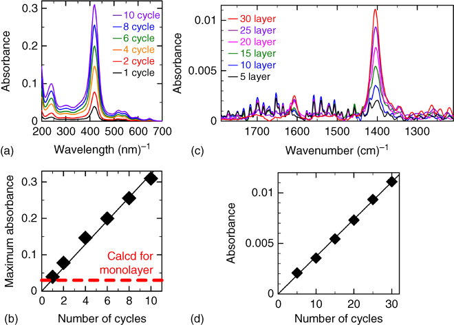
Figure 2.14 (a and b) Evolution of the UV–Vis absorption spectra (a) and IR absorption spectra (b) of NAFS‐2 on a SiO2/Cr/Au substrate with successive cycles of sheet deposition, rinsing, and drying. (c and d) Maximum absorbance of the H2TCPP Soret band (c) and the COO symmetric stretch band (d) of NAFS‐2 as a function of the number of film growth cycles.
2.4.6 Manipulation of the Layer Stacking Motif in MOF Nanosheets
Linkages between the neighboring layers can be tuned by introducing pillaring ligands (Figure 2.15). The nanosheets can also be layered by adjacent sheet adherence via weak van der Waals interactions when no pillaring ligands are applied (Figure 2.15a). On the other hand, introducing pillaring ligands between the layers that can coordinate to the available axial sites of metal ion linkers and project from the 2D network plane leads to the enlargement of the interlayer spacing (Figure 2.15b and c). Applying monodentate ligands expands the interlayer distance, but the neighboring sheets are not strongly bound (Figure 2.15b), while introducing bidentate ligands binds the neighboring sheets in an ordered manner – the lattice size of the attached sheet networks matches (Figure 2.15c) [77].
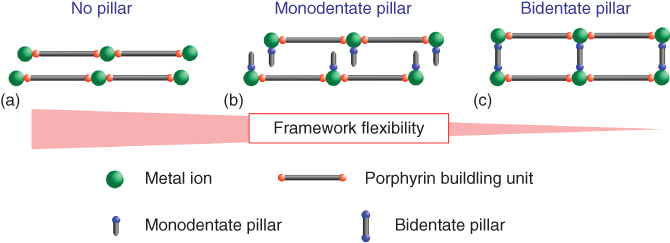
Figure 2.15 Schematic illustration of possible structural variations of MOF nanosheets by LbL growth.
Source: From Yamada et al. 2013 [77]. Reproduced with permission of Royal Society of Chemistry.
To investigate the assembly of a nonpillared structure, a free‐base porphyrin, H2TCPP was selected (Figure 2.16, left top). Applying pyridine (py) molecules as monodentate pillaring ligands together with a metalloporphyrin, CoTCPP (Figure 2.16, right top), was another combination of building components that could lead to the formation of an interdigitated stacking motif. Copper(II) ions were selected as the metal ion linkers for both molecular systems.

Figure 2.16 Schematic illustration of the MOF nanosheet fabrication protocol at the air/liquid interface and the molecular structures of the building units used. The combination of H2TCPP and copper ion leads to the formation of the nonpillar type of sheet described in Figure 2.15a, whereas the combination of CoTCPP, pyridine (py), and copper ion provides the sheet that includes the monodentate pillar projecting from the sheet plane, as shown in Figure 2.15b.
Source: From Yamada et al. 2013 [77]. Reproduced with permission of Royal Society of Chemistry.
The GI in‐plane XRD profiles of H2TCPP‐Cu (NAFS‐2) [76] and CoTCPP‐py‐Cu (NAFS‐1) [49] are shown in Figure 2.17. The number of sharp diffraction peaks indicates that both NAFS‐2 and NAFS‐1 are highly crystalline in the substrate‐plane direction. Very importantly, all of the reflections in both films could be indexed as (hk0) by using a pseudo‐2D tetragonal unit cell with basal plane dimensions, a = b = 16.477(2) Å in NAFS‐2 and 16.460(3) Å in NAFS‐1, supporting the adoption of a common 2D network, in which porphyrin units are linked by binuclear Cu2(COO)4 paddle wheels. This results in the checkerboard pattern shown in Figure 2.17a and b inset.
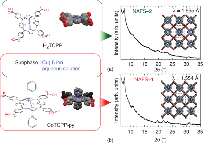
Figure 2.17 Grazing incidence synchrotron X‐ray diffraction profiles for NAFS films. (a, b) Observed wide‐range in‐plane XRD profiles for NAFS‐2 (a) and NAFS‐1 (b). The inset shows a schematic diagram of the proposed in‐plane crystalline structures and basal plane dimensions by using a pseudo‐2D tetragonal unit cell. The left image shows the combination of the molecular components and metal ion linkers – H2TCPP‐Cu for NAFS‐2 (top) and CoTCPP‐py‐Cu for NAFS‐1 (bottom).
Source: From Yamada et al. 2013 [77]. Reproduced with permission of Royal Society of Chemistry.
XRD measurements using the out‐of‐plane scattering geometry were also carried out. Figure 2.18 shows the wide‐range out‐of‐plane XRD patterns of the two nanofilms, NAFS‐2 and NAFS‐1. Observation of Bragg reflections reveals the highly oriented nature of both nanofilms. They can be indexed as (001) and (002) for NAFS‐2 (Figure 2.18a), and (001) and (003) for NAFS‐1 (Figure 2.18b), leading to values for the size of the interlayer spacing, c of 7.026(3) Å for NAFS‐2 and 9.380(3) Å for NAFS‐1; thus, the interlayer distance, c, in NAFS‐2 is significantly smaller than that found in NAFS‐1. This can be explained by the absence of pyridine molecules (Figure 2.18c). In NAFS‐1, pyridine molecules coordinate axially to both the copper binuclear units and the central metal ions of CoTCPP and protrude from each 2D sheet (Figure 2.18d). On the other hand, in NAFS‐2, water molecules are available to coordinate to the axial sites of the binuclear paddle‐wheel units to complete the coordination sphere. When we consider the sheets in NAFS‐2 with no water molecules coordinating to the axial sites, their thickness is estimated as ≈3.9 Å (i.e. the distance between hydrogen atoms of the phenyl rings connected to the carboxylic part, where the phenyl ring plane stands perpendicular to the porphyrin flat plane), which is much smaller than the observed interlayer spacing. The evaluated H2TCPP‐Cu sheet thickness taking into account such axially coordinated water molecules (i.e. the distance between hydrogen atoms of the coordinated water molecules across each sheet) is ≈7.6 Å. This value is slightly larger than the NAFS‐2 interlayer spacing obtained from the XRD measurements. This supports a sheet stacking pattern in NAFS‐2, in which adjacent sheets do not stack directly on top of each other along c where their in‐plane lattice matches but are arbitrarily shifted, arranging neighboring axially coordinated water molecules in the interlayer space away from each other and leading to a slightly smaller interlayer distance (Figure 2.18c) than the magnitude of the film thickness estimated by considering the attached water molecules.

Figure 2.18 Out‐of‐plane synchrotron X‐ray diffraction profiles for NAFS films and schematic images of the sheet stacking motifs. (a and b) Observed wide‐range out‐of‐plane XRD profiles for NAFS‐2 (a) and NAFS‐1 (b). (c and d) Schematic images of the layering manner in NAFS‐2 (c) and NAFS‐1 (d).
Source: From Yamada et al. 2013 [77]. Reproduced with permission of Royal Society of Chemistry.
In NAFS‐1, the observed interlayer spacing of 9.4 Å is significantly smaller than the calculated layer thickness (i.e. the distance between nitrogen atoms of the coordinated pyridine molecules across each sheet) of ≈12.4 Å. Therefore, an interlayer stacking order in which neighboring sheets are shifted along the a‐axis by 1/4 of the unit cell was considered. The interlayer stacking model includes the pyridine molecules, bound to both the cobalt ion at the center of the porphyrin and the Cu2(COO)4 paddle‐wheel units (Figure 2.18d). The simulated in‐plane XRD profile of NAFS‐1 taking into account such layer stacking corresponds well to the observed GI in‐plane pattern. Therefore, the results suggest that the π–π interaction plays an important role in controlling the direction of growth of NAFS‐1 as the axially coordinated pyridine molecules projecting from the 2D sheets allow each further layer to attach in a highly ordered interdigitated manner.
To obtain further structural information on the ordering of the stacking layers, we also carried out rocking curve (θ‐scan) measurements at the (001) peak position in the out‐of‐plane orientation (Figure 2.19). Rocking curves provide information on the degree of crystallinity. The full width at half maximum (FWHM) of a peak observed in the rocking curve of a layer‐structured material provides a measure of the average tilting angle of the stacking layers (Figure 2.19a). This was estimated to be ≈3° in NAFS‐2 (Figure 2.19b). The larger tilting angle than that in NAFS‐1 (0.3°) (Figure 2.19c) is attributed to the weaker interaction between the layers (Figure 2.19d), as in NAFS‐2 there are no “layer‐locking” molecules projecting from the 2D sheets to exercise stereoelectronic control.

Figure 2.19 Rocking curve θ scan at the (001) reflection position in the out‐of‐plane orientation. (a) Rocking curves provide information on the degree of crystallinity. Full width at the half maximum (FWHM) of a peak observed in the rocking curve of a layer‐structured material represents the average tilting angle of the stacking layers. (b and c) Rocking curves observed for the NAFS‐2 (b) and NAFS‐1 (c) films. (d and e) Schematic images of the layer stacking motif for NAFS‐2 (d) and NAFS‐1 (e).
Source: From Yamada et al. 2013 [77]. Reproduced with permission of Royal Society of Chemistry.
2.4.7 Manipulation of In‐Plane Molecular Arrangement in MOF Nanosheets
We start with a tetratopic porphyrin MOF nanofilm, NAFS‐2, the fabrication of which was described in the previous section and proceed to modify the size and shape of the framework. In order to achieve this, we employ two specially designed building units, namely a trans‐ditopic (trans‐5,15‐diphenyl‐10,20‐di(4‐carboxyphenyl)porphine, trans‐H2DCPP) and an expanded tetratopic porphyrin (5,10,15,20‐tetrakis[4‐(4‐carboxyphenylethynyl)phenyl]porphine, H2TCPEPP), and while we retain the copper(II) ions as linkers (Figure 2.20) [78]. The trans‐H2DCPP molecule is basically of the same size as the MTCPP porphyrins but it differs in its denticity – it incorporates only two carboxylic substituents in the trans peripheral phenyl parts and can act as a linear ditopic ligand. On the other hand, H2TCPEPP is a tetratopic ligand, but its size is significantly enlarged – the molecular size is now ∼24 Å (the distance between the two oxygen atoms of neighboring carboxylic acids), which represents a substantial increase relative to the corresponding size of MTCPP of ∼15 Å.
![Molecular structures of the porphyrin building units, 5,10,15,20-tetrakis(4-carboxyphenyl)-porphyrin (H2TCPP), trans-5,15-diphenyl-10,20-di(4-carboxyphenyl)porphine (trans-H2DCPP), and 5,10,15,20-tetrakis[4-(4-carboxyphenylethynyl)phenyl]porphine (H2TCPEPP).](http://images-20200215.ebookreading.net/4/1/1/9783527341634/9783527341634__molecular-technology-volume__9783527341634__images__c02f020.jpg)
Figure 2.20 Molecular structures of the porphyrin building units, 5,10,15,20‐tetrakis(4‐carboxyphenyl)‐porphyrin (H2TCPP), trans‐5,15‐diphenyl‐10,20‐di(4‐carboxyphenyl)porphine (trans‐H2DCPP), and 5,10,15,20‐tetrakis[4‐(4‐carboxyphenylethynyl)phenyl]porphine (H2TCPEPP).
Source: From Makiura et al. 2014 [78]. Reproduced with permission of John Wiley and Sons.
Grazing incidence in‐plane GIXRD patterns for trans‐H2DCPP‐Cu nanosheets (NAFS‐31) and H2TCPEP‐Cu nanosheets (NAFS‐41) fabricated on Si(100) substrates are shown in Figure 2.21. The observation of a number of sharp peaks in the profiles indicates that both NAFS‐31 and NAFS‐41 are highly crystalline in the substrate‐plane direction. The NAFS films composed of the tetratopic TCPP units adopt metrically tetragonal structures with in‐plane lattice parameters, a = b = 16.4–16.6 Å, which coincide with those of comparable bulk crystals composed of TCPP units. For NAFS‐31, the observed peak positions of the Bragg reflections cannot be described with a tetragonal unit cell but can be indexed on a metrically rhombic unit cell with basal plane dimensions, a = b = 23.00(5) Å and γ = 96.2(3)° (Figure 2.21a). The lattice size is approximately equal to the value obtained by multiplying the lattice dimensions of the NAFS‐1 sheets (16.46 Å) by √2, corresponding to the basal plane diagonal of the NAFS‐1 unit cell. Then the rhombic unit cell can be accounted for by the molecular arrangement shown in the right panel of Figure 2.21a. Four trans‐H2DCPP molecules are connected via binuclear copper paddle‐wheel units, forming a slightly distorted checkerboard motif. The distortion from square to rhombic geometry may be attributed to the reduced number of binding parts in trans‐H2DCPP. The tetratopic TCPP leads to a symmetric square grid assembly, which reflects the shape of the molecule and the square disposition of its connecting ligands. On the other hand, the ditopic trans‐H2DCPP in which the connecting carboxylate units are linearly arranged cannot form an undistorted square grid, leading to the development of a small in‐plane rhombic distortion.

Figure 2.21 Grazing incidence (GI) in‐plane synchrotron X‐ray diffraction (XRD) patterns (green dots) for NAFS‐31 (a) and NAFS‐41 (b) nanosheets (left panels). In‐plane lattice parameters and indexing of the Bragg peaks are shown in the plots. Derived structural models for NAFS‐31 (a) and NAFS‐41 (b) are shown in the right panels. Calculated GIXRD patterns (black lines) and reflection positions (black bars) using the structural models are also shown.
Source: From Makiura et al. 2014 [78]. Reproduced with permission of John Wiley and Sons.
On the other hand, all observed peaks in the GIXRD profile of NAFS‐41 composed of the hyperexpanded tetratopic H2TCPEPP building units index on a metrically tetragonal unit cell with basal plane dimensions, a = b = 25.63(2) Å (Figure 2.21b). This is significantly enlarged compared with the lattice size of NAFS films with MTCPP building units (a = b = 16.4−16.6 Å). The symmetry and size of the unit cell can be well accounted for by a structural model (Figure 2.21b, right panel), which incorporates an in‐plane structural motif comprising H2TCPEPP units linked by binuclear Cu2(COO)4 paddle‐wheel secondary building units and resulting in a similar 2D checkerboard pattern to that encountered in NAFS films composed of MTCPP.
Figure 2.22 summarizes the in‐plane molecular arrangements of NAFS‐31 and NAFS‐41 together with that of NAFS‐2 for comparison [78]. Calculated Connolly surfaces – graphical representations of the available empty space obtained with a 1.0 Å Connolly radius – are also included. The size of the in‐plane unit cell of NAFS‐31 is approximately twice that of NAFS‐2 – there are two porphyrin molecular units in the NAFS‐31 unit cell. The checkerboard framework of NAFS‐2 accommodates a single type of distorted hexagonal pore with an aperture of ∼10.5 Å. On the other hand, the absence of half of the binuclear Cu2(COO)4 paddle‐wheel connectors in NAFS‐31 partially open the framework walls and impose a different shape on the void space – in addition to the distorted hexagonal pores found in NAFS‐2, there are elongated narrow‐shaped pores, which result from the merging of the smaller pores following the framework wall removal. On the other hand, NAFS‐41 and NAFS‐2 are isoreticular with the unit cell of NAFS‐41 retaining the same square planar topology as in NAFS‐2. However, the linear extension of the four organic struts in NAFS‐41 is accompanied by a distinct expansion of the unit cell by ∼9 Å (25.63 Å in NAFS‐41, 16.48 Å in NAFS‐2) together with a simultaneous increase in the pore apertures. The dimension of the long diagonal of the pore apertures (the distance between the facing Connolly surfaces) estimated from the in‐plane structural model of NAFS‐41 is about 19.6 Å – double the size of that in NAFS‐2 (∼10.5 Å) – with a void area (∼196 Å2) four times as large as that of NAFS‐2 (∼43 Å2).
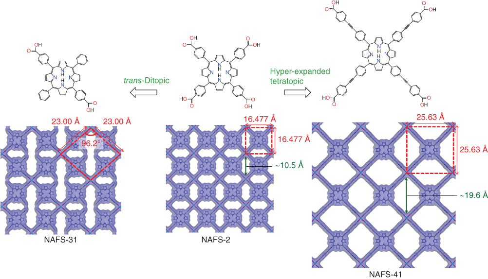
Figure 2.22 Summary of the in‐plane structural arrangements in porphyrin‐based MOF nanosheets assembled at the air/liquid interface. Molecular building units (top) and corresponding in‐plane crystalline structures (bottom) are shown together with the unit cells obtained from synchrotron GIXRD measurements and calculated Connolly surfaces.
Source: From Makiura et al. 2014 [78]. Reproduced with permission of John Wiley and Sons.
References
- 1 Ozin, G.A., Arsenault, A., and Cademartiri, L. (2008). Nanochemistry: A Chemical Approach to Nanomaterials: Edition 2. RSC Publishing.
- 2 Roberts, G. (1990). Langmuir–Blodgett Films. Springer.
- 3 Rayleigh, L. (1891). Surface tension. Nature 43: 437–439.
- 4 Pockels, A. (1892). On the relative contamination of the water‐surface by equal quantities of different substances. Nature 46: 418–419.
- 5 Langmuir, I. (1917). The constitution and fundamental properties of solids and liquids. II. Liquids. J. Am. Chem. Soc. 39: 1848–1906.
- 6 Blodgett, K.B. (1935). Films built by depositing successive monomolecular layers on a solid surface. J. Am. Chem. Soc. 57: 1007–1022.
- 7 Fujihira, M., Nishiyama, K., and Yamada, H. (1985). Photoelectrochemical responses of optically transparent electrodes modified with Langmuir–Blodgett films consisting of surfactant derivatives of electron donor, acceptor and sensitizer molecules. Thin Solid Films 132: 77–82.
- 8 Pedrosa, J.‐M., Romero, M.T.M., and Camacho, L. (2002). Organization of an amphiphilic azobenzene derivative in monolayers at the air‐water interface. J. Phys. Chem. B 106: 2583–2591.
- 9 Wang, R., Jiang, L., Iyoda, T. et al. (1996). Investigation of the surface morphology and photoisomerization of an azobenzene‐containing ultrathin film. Langmuir 12: 2052–2057.
- 10 Ariga, K. and Kunitake, T. (1998). Molecular recognition at air–water and related interfaces: complementary hydrogen bonding and multisite interaction. Acc. Chem. Res. 31: 371–378.
- 11 Obeng, Y.S. and Bard, A.J. (1991). Langmuir films of C60 at the air–water interface. J. Am. Chem. Soc. 113: 6279–6280.
- 12 Nakamura, T., Tachibana, H., Yumura, M. et al. (1992). Formation of Langmuir‐Blodgett films of a fullerene. Langmuir 8: 4–6.
- 13 Long, C.‐F., Xu, Y., Guo, F.‐X. et al. (1992). Lattice imaging of C60 Langmuir‐Blodgett films. Solid State Commun. 82: 381–383.
- 14 Cao, Y., Wei, Z., Liu, S. et al. (2010). High‐performance Langmuir–Blodgett monolayer transistors with high responsivity. Angew. Chem. Int. Ed. 49: 6319–6323.
- 15 Kan, J., Chen, Y., Qi, D. et al. (2012). High‐performance air‐stable ambipolar organic field‐effect transistor based on tris(phthalocyaninato) europium(III). Adv. Mater. 24: 1755–1758.
- 16 Murray, D.J., Patterson, D.D., Payamyar, P. et al. (2015). Large area synthesis of a nanoporous two‐dimensional polymer at the air/water interface. J. Am. Chem. Soc. 137: 3450–3453.
- 17 Smith, K.M. (1972). Porphyrins and Metaloporphyrins. Elsevier.
- 18 Sheldon, R.A. (1994). Metalloporphyrins in Catalytic Oxidations. Marcel Dekker.
- 19 Kadish, K., Smith, K.M., and Guiard, R. (2003). The Porphyrin Handbook, vol. 1999. Academic Press.
- 20 Lee, S.J. and Hupp, J.T. (2006). Porphyrin‐containing molecular squares: design and applications. Coord. Chem. Rev. 250: 1710–1723.
- 21 Suslick, K.S., Bhyrappa, P., Chou, J.‐H. et al. (2005). Microporous porphyrin solids. Acc. Chem. Res. 38: 283–291.
- 22 Goldberg, I. (2008). Crystal engineering of nanoporous architectures and chiral porphyrin assemblies. CrystEngComm 10: 637–645.
- 23 Drain, C.M., Varotto, A., and Radivojevic, I. (2009). Self‐organized porphyrinic materials. Chem. Rev. 109: 1630–1658.
- 24 Qian, D.‐J., Nakamura, C., and Miyake, J. (2001). Spectroscopic studies of the multiporphyrin arrays at the air–water interface and in Langmuir–Blodgett films. Thin Solid Films 397: 266–275.
- 25 Qian, D.‐J., Nakamura, C., and Miyake, J. (2000). Multiporphyrin array from interfacial metal‐mediated assembly and its Langmuir‐Blodgett films. Langmuir 16: 9615–9619.
- 26 Zhang, C.‐F., Chen, M., Nakamura, C. et al. (2008). Electrochemically driven generation of manganese(IV,V)‐oxo multiporphyrin arrays and their redox properties with manganese(III) species in Langmuir‐Blodgett films. Langmuir 24: 13490–13495.
- 27 Qian, D.‐J., Nakamura, C., and Miyake, J. (2001). Layer‐by‐layer assembly of metal‐mediated multiporphyrin arrays. Chem. Commun. 2312–2313.
- 28 Liu, B., Qian, D.‐J., Chen, M. et al. (2006). Metal‐mediated coordination polymer nanotubes of 5,10,15,20‐tetrapyridylporphine and tris(4‐pyridyl)‐1,3,5‐triazine at the water–chloroform interface. Chem. Commun. 3175–3177.
- 29 Liu, B., Qian, D.‐J., Huang, H.‐X. et al. (2005). Controllable growth of well‐defined regular multiporphyrin array nanocrystals at the water–chloroform interface. Langmuir 21: 5079–5084.
- 30 Drain, C.M., Nifiatis, F., Vasenko, A., and Batteas, J.D. (1998). Porphyrin tessellation by design: metal‐mediated self‐assembly of large arrays and tapes. Angew. Chem. Int. Ed. 37: 2344–2347.
- 31 Milic, T.N., Chi, N., Yablon, D.G. et al. (2002). Controlled hierarchical self‐assembly and deposition of nanoscale photonic materials. Angew. Chem. Int. Ed. 41: 2117–2119.
- 32 Milic, T.N., Garno, J.C., Batteas, J.D. et al. (2004). Self‐organization of self‐assembled tetrameric porphyrin arrays on surfaces. Langmuir 20: 3974–3983.
- 33 Yaghi, O.M., O'Keeffe, M., Ockwig, N.W. et al. (2003). Reticular synthesis and the design of new materials. Nature 423: 705–714.
- 34 Férey, G. (2008). Hybrid porous solids: past, present, future. Chem. Soc. Rev. 37: 191–214.
- 35 Kitagawa, S., Kitaura, R., and Noro, S. (2004). Functional porous coordination polymers. Angew. Chem. Int. Ed. 43: 2334–2375.
- 36 Li, Q., Zhang, W., Miljanić, O.Š. et al. (2009). Docking in metal–organic frameworks. Science 325: 855–859.
- 37 Li, J.‐R., Sculley, J., and Zhou, H.‐C. (2012). Metal–organic frameworks for separations. Chem. Rev. 112: 869–932.
- 38 Yerushalmi, R., Scherz, A., and Van Der Boom, M.E. (2004). Enhancement of molecular properties in thin films by controlled orientation of molecular building blocks. J. Am. Chem. Soc. 126: 2700–2701.
- 39 Hermes, S., Schröder, F., Chelmowski, R. et al. (2005). Selective nucleation and growth of metal–organic open framework thin films on patterned COOH/CF3‐terminated self‐assembled monolayers on au (111). J. Am. Chem. Soc. 127: 13744–13745.
- 40 Biemmi, E., Scherb, C., and Bein, T. (2007). Oriented growth of the metal organic framework Cu3(BTC)2(H2O)3·xH2O Tunable with functionalized self‐assembled monolayers. J. Am. Chem. Soc. 129: 8054–8055.
- 41 Haruki, R., Sakata, O., Yamada, T. et al. (2008). Structural evaluation of an iron oxalate complex layer grown on an ultra‐smooth sapphire (0001) surface by a wet method. Transactions of the Materials Research Society of Japan 33: 629–631.
- 42 Zacher, D., Schmid, R., Wöll, C., and Fischer, R.A. (2010). Surface chemistry of metal–organic frameworks at the liquid–solid interface. Angew. Chem. Int. Ed. 50: 176–199.
- 43 Liu, B., Tu, M., Zacher, D., and Fischer, R.A. (2013). Multi variant surface mounted metal–organic frameworks. Adv. Funct. Mater. 23: 3790–3798.
- 44 Sakata, Y., Furukawa, S., Kondo, M. et al. (2013). Shape‐memory nanopores induced in coordination frameworks by crystal downsizing. Science 339: 193–196.
- 45 Xu, G., Yamada, T., Otsubo, K. et al. (2012). Facile “modular assembly” for fast construction of a highly oriented crystalline MOF nanofilm. J. Am. Chem. Soc. 134: 16524–16527.
- 46 Lee, H.J., Cho, Y.J., Cho, W., and Oh, M. (2013). Controlled isotropic or anisotropic nanoscale growth of coordination polymers: formation of hybrid coordination polymer particles. ACS Nano 7: 491–499.
- 47 Falcaro, P., Buso, D., Hill, A.J., and Doherty, C.M. (2012). Patterning techniques for metal organic frameworks. Adv. Mater. 24: 3153–3168.
- 48 Falcaro, P., Ricco, R., Doherty, C.M. et al. (2014). MOF positioning technology and device fabrication. Chem. Soc. Rev. 43: 5513–5560.
- 49 Makiura, R., Motoyama, S., Umemura, Y. et al. (2010). Surface nano‐architecture of a metal–organic framework. Nat. Mater. 9: 565–571.
- 50 Makiura, R. and Kitagawa, H. (2010). Porous porphyrin nanoarchitectures on surfaces. Eur. J. Inorg. Chem. (24): 3715–3724.
- 51 Makiura, R., Tsuchiyama, K., and Sakata, O. (2011). Self‐assembly of highly crystalline two‐dimensional MOF sheets on liquid surfaces. Cryst. Eng. Comm. 13: 5538–5541.
- 52 Makiura, R. and Konovalov, O. (2013). Interfacial growth of large‐area single‐layer metal–organic framework nanosheets. Sci. Rep. 3: 2506–2513.
- 53 Choi, E.‐Y., Barron, P.M., Novotny, R.W. et al. (2009). Pillared porphyrin homologous series: intergrowth in metal–organic frameworks. Inorg. Chem. 48: 426–428.
- 54 Chung, H., Barron, P.M., Novotny, R.W. et al. (2009). Structural variation in porphyrin pillared homologous series: influence of distinct coordination centers for pillars on framework topology. Cryst. Growth Des. 9: 3327–3332.
- 55 Choi, E.‐Y., Wray, C.A., Hu, C., and Choe, W. (2009). Highly tunable metal–organic frameworks with open metal centers. CrystEngComm 11: 553–555.
- 56 Makiura, R., Usui, R., Pohl, E., and Prassides, K. (2014). Porphyrin‐based coordination polymer composed of layered pillarless two‐dimensional networks. Chem. Lett. 43: 1161–1163.
- 57 Makiura, R. and Konovalov, O. (2013). Bottom‐up assembly of ultrathin sub‐micron size metal–organic framework sheets. Dalton Trans. 42: 15931–15936.
- 58 Decher, G., Hong, J.D., and Schmitt, J. (1992). Buildup of ultrathin multilayer films by a self‐assembly process: III. Consecutively alternating adsorption of anionic and cationic polyelectrolytes on charged surfaces. Thin Solid Films 210–211: 831–835.
- 59 Lvov, Y., Decher, G., and Möhwald, H. (1993). Assembly, structural characterization, and thermal behavior of layer‐by‐layer deposited ultrathin films of poly(vinyl sulfate) and poly(allylamine). Langmuir 9: 481–486.
- 60 Ariga, K., Yamauchi, Y., Rydzek, G. et al. (2014). Layer‐by‐layer nanoarchitectonics: invention, innovation, and evolution. Chem. Lett. 43: 36–68.
- 61 Richardson, J.J., Cui, J., Björnmalm, M. et al. (2016). Innovation in layer‐by‐layer assembly. Chem. Rev. 116: 14828–14867.
- 62 Sinha Ray, S. and Okamoto, M. (2003). Polymer/layered silicate nanocomposites: a review from preparation to processing. Prog. Polym. Sci. 28: 1539–1641.
- 63 Kovtyukhova, N.I. (1999). Layer‐by‐layer assembly of ultrathin composite films from micron‐sized graphite oxide sheets and polycations. Chem. Mater. 11: 771–778.
- 64 Lvov, Y., Ariga, K., Ichinose, I., and Kunitake, T. (1995). Assembly of multicomponent protein films by means of electrostatic layer‐by‐layer adsorption. J. Am. Chem. Soc. 117: 6117–6123.
- 65 Yang, H.C., Aoki, K., Hong, H.‐G. et al. (1993). Growth and characterization of metal(II) alkanebisphosphonate multilayer thin films on gold surfaces. J. Am. Chem. Soc. 115: 11855–11862.
- 66 Altman, M., Shukla, A.D., Zubkov, T. et al. (2006). Controlling structure from the bottom‐up: structural and optical properties of layer‐by‐layer assembled palladium coordination‐based multilayers. J. Am. Chem. Soc. 128: 7374–7382.
- 67 Haga, M., Kobayashi, K., and Terada, K. (2007). Fabrication and functions of surface nanomaterials based on multilayered or nanoarrayed assembly of metal complexes. Coord. Chem. Rev. 251: 2688–2701.
- 68 Nishihara, H., Kanaizuka, K., Nishimori, Y., and Yamanoi, Y. (2007). Construction of redox‐ and photo‐functional molecular systems on electrode surface for application to molecular devices. Coord. Chem. Rev. 251: 2674–2687.
- 69 Zacher, D., Shekhah, O., Wöll, C., and Fischer, R.A. (2009). Thin films of metal–organic frameworks. Chem. Soc. Rev. 38: 1418–1429.
- 70 Shekhah, O., Wang, H., Kowarik, S. et al. (2007). Step‐by‐step route for the synthesis of metal–organic frameworks. J. Am. Chem. Soc. 129: 15118–15119.
- 71 Shekhah, O., Wang, H., Strunskus, T. et al. (2007). Layer‐by‐layer growth of oriented metal organic polymers on a functionalized organic surface. Langmuir 23: 7440–7442.
- 72 Munuera, C., Shekhah, O., Wang, H. et al. (2008). The controlled growth of oriented metal–organic frameworks on functionalized surfaces as followed by scanning force microscopy. Phys. Chem. Chem. Phys. 10: 7257–7261.
- 73 Shekhah, O., Wang, H., Paradinas, M. et al. (2009). Controlling interpenetration in metal–organic frameworks by liquid‐phase epitaxy. Nat. Mater. 8: 481–484.
- 74 Shekhah, O., Wang, H., Zacher, D. et al. (2009). Growth mechanism of metal–organic frameworks: insights into the nucleation by employing a step‐by‐step route. Angew. Chem. Int. Ed. 48: 5038–5041.
- 75 Kanaizuka, K., Haruki, R., Sakata, O. et al. (2008). Construction of highly oriented crystalline surface coordination polymers composed of copper dithiooxamide complexes. J. Am. Chem. Soc. 130: 15778–15779.
- 76 Motoyama, S., Makiura, R., Sakata, O., and Kitagawa, H. (2011). Highly crystalline nanofilm by layering of porphyrin metal–organic framework sheets. J. Am. Chem. Soc. 133: 5640–5643.
- 77 Yamada, T., Otsubo, K., Makiura, R., and Kitagawa, H. (2013). Designer coordination polymers: dimensional crossover architectures and proton conduction. Chem. Soc. Rev. 42: 6655–6669.
- 78 Makiura, R., Usui, R., Sakai, Y. et al. (2014). Towards rational modulation of in‐plane molecular arrangements in metal–organic framework nanosheets. ChemPlusChem 79: 1352–1360.