
10
Molecular Design of Photocathode Materials for Hydrogen Evolution and Carbon Dioxide Reduction
Christopher D. Windle1, Soundarrajan Chandrasekaran1, Hiromu Kumagai2 Go Sahara2 Keiji Nagai3 Toshiyuki Abe4, Murielle Chavarot‐Kerlidou1, Osamu Ishitani2 and Vincent Artero1
1 Univ Grenoble Alpes, CNRS, Commissariat à l'Energie Atomique (CEA), Laboratoire de Chimie et Biologie des Métaux, 17 rue des Martyrs, 38000 Grenoble, France
2 Tokyo Institute of Technology, School of Science, Department of Chemistry, O‐okayama 2‐12‐1‐NE‐1, Meguro‐ku, Tokyo, 152‐8550, Japan
3 Tokyo Institute of Technology, Institute of Innovative Research (IIR), Laboratory for Chemistry and Life Science, R1‐26, Nagatsuda 4259, Midori‐ku Yokohama, Kanagawa, 226‐8503, Japan
4 Hirosaki University, Graduate School of Science and Technology, Department of Frontier Materials Chemistry, 3 Bunkyo‐cho, Hirosaki, 036‐8561, Japan
10.1 Introduction
Solar energy research is the spearhead of non‐carbon‐based energy technologies because only solar energy can provide the additional >14 TW required to fulfil our societal needs by 2050 [1, 2]. This huge energy input, however, must be stored in a durable way because of the mismatch between solar energy availability and economic or domestic demand. Towards this objective, producing fuels from available resources such as water and carbon dioxide is an attractive solution. Such an endeavour is often referred to as artificial photosynthesis because it mimics the properties of plants, algae and some bacteria to harvest solar energy and to use it to produce the chemicals that fuel their metabolism. Most photosynthetic organisms convert carbon dioxide into organic compounds, but some micro‐algae and cyanobacteria are able, under certain conditions, to produce molecular hydrogen from sunlight in water. Producing hydrogen through water splitting or combining CO2 reduction with water oxidation thus appear as two attractive solutions to store the abundant flow of sunlight falling on Earth. A close‐to‐market way to convert solar energy into hydrogen is to interface photovoltaic technologies with electrolysis technologies. However, natural systems exploit molecular photosensitisers (such as chlorophylls, for example) and molecular catalytic active sites in enzymes to achieve this process. A closer look at the organisation of the photosynthetic chain (Figure 10.1) shows that (i) each enzymatic site (the oxygen‐evolving centre (OEC) in photosystem II or FNR‐producing NAD(P)H‐/hydrogenases‐producing H2) is coupled to a photosystem, (ii) oxidative and reductive photocatalytic systems are coupled through an electron transfer chain and (iii) the whole system is immobilised onto a membrane. A possible way to reproducing such a highly complex organisation in an artificial system is through the construction of so‐called photoelectrochemical cells (Figure 10.2) that combine a photoanode achieving water oxidation and a photocathode able to produce hydrogen [3–5] or reduce CO2 [6, 7]. A number of experimental demonstrations have already been reported, most of them relying on the use of solid‐state semiconductor and catalysts for water oxidation, hydrogen evolution or CO2 reduction [8]. In terms of efficiency, limitation currently arises from the photocathode performances and their design will constitute the topic of this chapter, with an emphasis on molecular design, that is, the integration of either a molecular‐based photoactive material or a molecular catalyst. The role of a fuel‐forming photocathode can be split into three parts. It must (i) absorb and convert sunlight energy into excitons, (ii) separate the charges and (iii) reduce H+ to H2 or reduce CO2. In this chapter, we focus on photocathodes where at least one of those roles is performed by a molecular component.
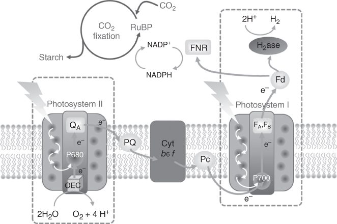
Figure 10.1 Schematic representation of the photosynthetic chain.

Figure 10.2 Schematic representation of photoelectrochemical cells (PECs) for water splitting or CO2 reduction coupled with water oxidation.
10.2 Photocathode Materials for H2 Evolution
We have broken this first part into three sections separated by the nature of the component performing the absorption and conversion of sunlight. We begin with systems where the light absorber is a solid‐state semiconducting material and typically an inorganic extended solid. In most cases, this material is p‐type and is also responsible for charge separation. The molecular component is the H+ reduction catalyst. The second part discusses dye‐sensitised systems where a molecular dye is responsible for solar energy conversion. Charge separation is provided by a solid‐state semiconductor that does not efficiently absorb solar light. H+ reduction is mediated by a molecular catalyst. The third part is concerned with systems in which an organic semiconducting material converts solar energy. These materials are blended to create a p–n junction that separates the charges and a catalyst is added for H+ reduction.
10.2.1 Molecular Photocathodes for H2 Evolution Based on Low Bandgap Semiconductors
This part is focused on p‐type inorganic semiconductors grafted with molecular catalysts [9] as photocathodes for H2 evolution. The inorganic semiconductors currently in the limelight are silicon (Si, 1.1 eV bandgap), gallium phosphide (GaP, 2.2 eV bandgap), indium phosphide (InP, 1.3 eV bandgap), cuprous oxide (Cu2O, 2.1 eV bandgap) and gallium indium phosphide (GaInP2, 1.8 eV bandgap). They all possess a low bandgap responsible for visible‐light absorption [10, 11].
In the following, we will present the different photoelectrodes reported so far with a specific focus on the various methodologies used to construct such hybrid systems.
10.2.1.1 Molecular Catalysts Physisorbed on a Semiconductor Surface
The simplest method that has been used is to simply physisorb a molecular catalyst onto the semiconductor surface. This can be done by drop‐casting or soaking method. Nann et al. [12] used an iron sulfur carbonyl catalyst [Fe2S2(CO)6], which can be considered as a mimic of the catalytic subsite of [FeFe] hydrogenase enzyme and therefore capable for catalytic proton reduction, to fabricate an InP‐based photocathode (Figure 10.3). The photocathode fabrication involves the layer‐by‐layer coating (10 layers) of InP quantum dots (QDs) onto gold support using thiol chemistry. The modified photocathode was immersed in a toluene solution of the synthetic mimic overnight, to allow spontaneous attachment of the diiron mimic onto InP QDs. Photoelectrolysis at −0.4 V vs Ag/AgCl in sodium tetrafluoroborate aqueous electrolyte in a three‐electrode system produced ∼250 nA cm−2 current density under illumination with a 395 nm LED array. The current density was stable for 1 h.
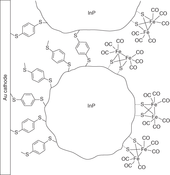
Figure 10.3 Structure of the InP‐based electrode with physisorbed diiron catalyst.
Source: From Nann et al. [12]. Reproduced with permission of John Wiley & Sons.
The same [Fe2S2(CO)6] catalyst has also been physisorbed on planar silicon [13] and nanostructured silicon such as porous silicon [14, 15], porous silicon nanoparticles [16], silicon nanowires [13] and diatom‐derived silicon [17] to fabricate photoelectrodes for H2 production. Photoelectrolysis was carried out in 0.5 M sulfuric acid (∼pH 0.3) as an electrolyte in a three‐electrode system under illumination with an Abet solar simulator (1 sun irradiation). A comparison of the studies using [Fe2S2(CO)6] catalyst based on the approximate current density and faradaic efficiency is shown in Table 10.1. Stable photocurrents were observed for porous silicon and silicon nanowire photocathodes coated with [Fe2S2(CO)6] catalyst for a reasonable amount of time. Although planar silicon coated with [Fe2S2(CO)6] catalyst showed higher photocurrents than porous silicon with [Fe2S2(CO)6] catalyst, stability was a major concern with planar silicon. In the case of particle systems coated with [Fe2S2(CO)6] catalyst such as InP QDs, porous silicon nanoparticles and diatom‐derived silicon, lower photocurrent values and modest stability were observed when compared with robust porous silicon and silicon nanowire systems, respectively. The reason perhaps the low electronic conduction between particles and varied amount of particles attached on the electrode surface. However, silicon‐based molecular photocathodes improved the current density and, therefore, H2 production, by several orders of magnitude when compared with previous work by Nann et al. [12].
Table 10.1 Comparison of the studies involving molecular photocathodes coated with [Fe2S2(CO)6] catalyst at pH = 0.3 under illumination with an Abet solar simulator.
| Photocathodes coated with [Fe2S2(CO)6] | Applied potential (V vs RHE) | Current density (A cm−2) | Faradaic efficiency (%) | References |
| Gold electrode coated with InP QDs | −0.14 | 0.25 × 10⁻⁶ | 60 | [12] |
| Planar silicon | −0.24 | 5.00 × 10⁻³ | 77 | [13] |
| Porous silicon | −0.24 | 2.80 × 10⁻³ | 90 | [14, 15] |
| Porous silicon nanoparticles | −0.13 | 2.20 × 10⁻⁶ | 14 | [16] |
| Diatom‐derived silicon | −0.24 | 6.00 × 10⁻⁶ | 12 | [17] |
| Silicon nanowire | −0.24 | 17.00 × 10⁻³ | 99 | [13] |
Chorkendorff and coworkers used the same strategy to decorate naked H‐terminated p‐Si(100) photocathodes with various sulfide clusters of molybdenum and tungsten (Figure 10.4) [18, 19]. Excellent photocurrent densities (12–14 mA cm−2 at saturation) were observed under red light irradiation. Clearly, molybdenum‐based clusters (8 mA cm−2 at 0 V vs. reversible hydrogen electrode (RHE)) are more efficient than tungsten‐based clusters (8 mA cm−2 at 0.3–0.35 V vs RHE) to promote catalysis at low applied potentials. The presence of Cu in the tetranuclear clusters does not influence the results, whereas Co‐based clusters yield unstable performances. Slightly better performances are obtained when using silicon nanopillars [19]. Except for electrodes based on Co/W and Co/Mo clusters, stable performance over 1 h was observed with less than 5% loss of the photocurrent density over the first 30 min.

Figure 10.4 Structure of the bioinspired sulfide clusters of molybdenum and tungsten used as hydrogen‐evolving catalysts by Chorkendorff and coworkers [18] to decorate silicon‐based photocathodes.
10.2.1.2 Covalent Attachment of the Catalyst to the Surface of the Semiconductor
To better control the stability of the catalyst linkage, molecular technologies based on semiconductor surface chemistry have been developed. Two approaches have been used. The first one consists in directly functionalising the surface of the naked semiconductor, whereas the second relies on the coating of the semiconductor with a layer of transparent metal oxide onto which the catalyst is covalently grafted.
The surface chemistry of silicon and other II–V semiconductors is rich and allows for the creation of stable covalent E−C (E = Si, Ga, …) bonds. For example, UV light can be used to induce the coupling of alkene to p‐Si(111) and p‐GaP(100) surfaces. This allowed Moore and Sharp to decorate such surfaces by protected pendant amino groups [20]. Further deprotection of the amino groups followed by amide coupling with a phthalimide‐functionalised nickel bis(diphosphine) catalyst, initially developed for a covalent attachment onto carbon nanotubes (CNTs) [21, 22], gave semiconductor substrates bearing the nickel complex at the surface as shown by grazing angle‐attenuated total reflectance (GATR) FTIR and XPS spectroscopies. GATR‐FTIR spectra of the functionalised substrates also display a vibrational band characteristic of surface oxide layers likely formed during surface functionalisation. No photoelectrochemical activity is reported for this construct, likely due to the presence of this passivating layer. In another study, the same methodology was used to graft a cobalt or iron porphyrins at the surface of p‐GaP(100) substrate (Figure 10.5) [24]. These electrodes proved active for light‐driven hydrogen evolution with photocurrents up to 1.3 mA cm−2 at 0 V vs RHE in 0.1 M phosphate buffer (pH 7) and 1 mA cm−2 at 0.35 V vs RHE for the cobalt porphyrin system. The current density was found to be stable for >5 min.

Figure 10.5 Structures of molecular‐based electrodes based on p‐Si [23] or p‐GaP [24] semiconductor materials.
Rose and coworkers were successful in immobilising a nickel bis(diphosphine) complex (Figure 10.5) starting for a chlorinated p‐Si(111) wafer by a stepwise surface modification procedure exploiting palladium‐catalysed coupling chemistry [23]. Unreactive sites are blocked with methyl residues, which provide a good stability upon cycling in CH3CN in the presence of trifluoroacetic acid (TFA). A 2.5 × 10⁻¹⁰ mol cm−2 surface concentration of the Ni catalyst was estimated from XPS and electrochemical characterisations. Under 33 mW cm−2 broadband LED irradiation, the onset HER potential was found at −0.06 V vs. normal hydrogen electrode (NHE), only 40 mV more negative than a control Pt‐coated p‐Si electrode. The covalently assembled semiconductor–molecular catalyst construct has an onset for light‐driven HER shifted 200 mV more positive than a methylated p‐Si photoelectrode in contact with a solution of the same catalyst.
An alternative method consists in coating the surface of the semiconductor by a layer of a transparent conducting or semiconducting oxide, typically TiO2. Then the catalyst can be attached onto the metal‐oxide surface through the covalent binding of phosphonate or carboxylate groups. This stepwise functionalisation permits to take benefit of the three‐dimensional structuration of the metal‐oxide layer to increase catalyst loading. In addition, the deposition of a protection layer can be well controlled with such a stepwise strategy. A thin Ti layer or atomic layer deposition (ALD)‐deposited TiO2 layers have been used in this context. Actually, this strategy was first used by Chorkendorff and coworkers as an alternative of the drop‐casting method presented above. Planar n+p silicon electrode was first protected by a 7‐nm‐thick metallic Ti layer and then coated with a 100‐nm‐thick TiO2 film. A [Mo3S4] cluster bearing phosphonate functional groups was then attached onto the TiO2 surface to yield an efficient photocathode developing 20 mA cm−2 current density at 0 V vs. RHE and proven stability over 1 h (Figure 10.6) [25].

Figure 10.6 Structure of photoelectrodes based on H2‐evolving catalysts attached onto TiO2 via phosphonate [25] and carboxylate linkages [26].
Turner and coworkers used a similar strategy to graft a cobaloxime catalyst onto TiO2‐protected GaInP2 semiconductor [26]. ALD was first used to protect the GaInP2 surface against oxidative corrosion. A 35‐nm‐thick TiO2 film proved optimal to obtain good photoelectrocatalytic performances after soaking the electrode in an ethanolic solution of a picolinic acid derivative of a cobaloxime. Further stabilisation of the electrode construct was demonstrated when additional layers of TiO2 (10 cycles) were deposited using ALD (Figure 10.6). Current density up to 9 mA cm−2 was measured at 0 V vs. RHE under 1‐Sun irradiation. The photocathode showed an initial decay of the photocurrent over the first 4 h and the current density was then sustained for 16 h at ∼5 mA cm−2 corresponding to a turnover frequency (TOF) of 1.9 s−1 in 0.1 M sodium hydroxide (pH 13).
Similarly, a molecular nickel bidiphosphine catalyst was attached through phosphonate linkage onto a silicon photocathode protected by an organic dimethoxyphenyl monolayer embedded into an aluminium–zinc oxide layer capped with a 20‐Å‐thick TiO2 layer [27]. The passivation of the silicon surface with organic and inorganic coatings improved the stability as well as charge extraction towards the interface with the electrolyte where the catalyst operates. The onset potential was ∼200 mV more positive for such a semiconductor/organic coating/AZO/TiO2 molecular catalyst system compared with semiconductor/organic coating/TiO2 molecular catalyst system.
10.2.1.3 Covalent Attachment of the Catalyst Within an Oligomeric or Polymeric Material Coating the Semiconductor Surface
Although it is the last presented here, this strategy has been the first to be implemented to construct a H2‐evolving photocathode based on silicon. In 1984, Mueller‐Westerhoff and Nazzal [28] covalently attached a 1‐methyl‐ferrocenophane catalyst to polymethylstyrene and coated this polymer onto a p‐type silicon photocathode (Figure 10.7). The polystyrene film was also used to protect the silicon surface from corrosion. H2 evolution was observed with a saturating current density of 230 mA cm−2 under 9 suns for 5 days in neat boron trifluoride hydrate electrolyte, the high acidity of which probably prevents passivation of the silicon electrode. H2 evolution was also observed in aqueous acidic electrolytes such as perchloric acid (HClO4), fluoroboric acid and hydrochloric acid. This field experienced a renaissance 5 years ago with the work of Moore and coworkers [29]. These authors investigated cobaloxime catalysts on GaP semiconductor photocathodes for H2 evolution. Two different polymeric frameworks, polyvinylpyridine (PVP) [30, 31] and polyvinylimidazole (PVI) [32, 33], were investigated, both of which are able to coordinate cobaloxime in axial positions thanks to their pyridine or imidazole residues. Table 10.2 gathers the results obtained for based on H‐bridged cobaloximes [30, 31] as well as BF2‐annulated cobaloximes [34]. Parameters such as light intensity [31], pH [34], orientation and crystal faces of GaP [33] have been varied. Table 10.2 can be summarised that H‐bridged cobaloxime shows greater efficiency when PVP was used a grafting polymer at pH 7, whereas BF2‐annulated cobaloxime shows greater efficiency with PVP grafting polymer at pH 4.5 (Figure 10.7). This observation is to be confirmed with PVI grafting polymer, but is in line with previous observations that BF2‐annulated cobaloximes require more acidic conditions to mediate electrocatalytic H2 evolution [35, 36].

Figure 10.7 Structure of various photoelectrodes based on ferrocenophane [28] and cobaloxime [29] catalysts embedded or grafted in polymeric frameworks.
Table 10.2 The reports by Moore and coworkers based on GaP‐modified cobaloxime photocathodes.
| Cobaloxime | Grafting polymer | pH | Illumination (100 mW cm−2) | Orientation and crystal faces | j at 0 V vs RHE (mA cm−2) | References |
| H‐bridged | PVP | 7 | Newport Oriel apex illuminator model 71228 light source | 100 | ∼2.80 | [30] |
| BF2‐annulated | PVP | 7 | Solar light PV cell test simulator model 16S‐300‐005V4.0 xenon lamp | 100 | ∼0.90 | [31] |
| H‐bridged | PVP | 7 | PV cell testing 16S 300 W solar simulator | 100 | 1.20 | [34] |
| H‐bridged | PVP | 4.5 | PV cell testing 16S 300 W solar simulator | 100 | ∼1.15 | [34] |
| BF2‐annulated | PVP | 7 | PV cell testing 16S 300 W solar simulator | 100 | 0.56 | [34] |
| BF2‐annulated | PVP | 4.5 | PV cell testing 16S 300 W solar simulator | 100 | ∼1.15 | [34] |
| H‐bridged | PVI | 7 | 100 W Oriel solar simulator | 111A | ∼0.89 | [33] |
| H‐bridged | PVI | 7 | 100 W Oriel solar simulator | 111B | ∼0.89 | [33] |
| H‐bridged | PVP | 7 | 100 W Oriel solar simulator | 100 | ∼1.3 | [32] |
| H‐bridged | PVI | 7 | 100 W Oriel solar simulator | 100 | ∼1.2 | [32] |
In conclusion, light‐harvesting semiconductor‐tethered molecular catalyst systems seem promising for H2 production, especially as modern techniques allow to overcome surface passivation issues. However, the fabrication of bulk semiconductors often depends on rare earth elements such as In, Ga or Ge, which is not always economically viable; organic photovoltaic solar cells may be a cost‐effective alternative with identical designs of semiconductor systems.
10.2.2 H2‐evolving Photocathodes Based on Organic Semiconductors
Organic semiconductor materials (OSCs) are conducting polymers, oligomers or self‐assembled discrete molecules that use abundant materials and can be deposited using low‐cost solution‐based processes. Additionally, OSCs display high optical absorption in the visible region of the solar spectrum. They generally possess much more reducing excited states than inorganic semiconductors and their electronic properties can be easily tuned through structural modifications [37]. These materials allowed to develop organic solar cells reaching 10% of power conversion efficiency (PCE) [38]. Light‐induced charge separation is achieved at the interface between the two OSCs. Upon absorption of a photon in one of the OSCs, an exciton (i.e. a pair of electrostatically bound electron and hole) forms and then migrates to the junction with the other OSC. Here, the exciton dissociates, resulting in the appearance of a hole in one OSC called the donor and an electron in the other OSC called the acceptor. In photovoltaic cells, electrons and holes then migrate to the electrodes where charges are collected. A key issue is the structuration of the two materials as excitons can only diffuse over a few tens of nanometres during their lifetime, that is, before spontaneous recombination takes place. Therefore, the two OSCs must be either deposited as two very thin layers, possibly with an interlayer containing both compounds, yielding a mixed interlayer junction, or as a blend of the two materials forming molecular p–n junctions all over the bulk layer (bulk heterojunction, BHJ). In general, BHJs are formed between a polymer or an array of small molecules, acting as the light absorber, and a fullerene derivative [39]. To use such organic junctions in the context of direct photoelectrochemical water splitting, different conditions should be met: (i) the organic layer in contact with a liquid electrolyte must maintain the capacity of light absorption and generating charges as well as the internal charge separation and transport to the active surface; (ii) an appropriate photovoltage must be reached to allow charge transfer between the organic layer and an acceptor located in the electrolyte or at the surface of the photoelectrode and (iii) the electrochemical reaction at the organic semiconductor/liquid electrolyte interface must be facilitated by an appropriate catalyst. Early reports described photocathodes made of conducting polymers, such as polyacetylene (CH) [40], polypyrrole [41], polyaniline [42], poly(3‐methylthiophene) [43] or poly(3‐hexylthiophene) (P3HT) [44, 45]. However, these photoelectrodes did not contain any junction between OSCs nor HER catalysts and charge separation arise from the Schottky junction between p‐type OSC and electrolyte. Hence, only low photocurrents (few to tens of microamperes per square centimetre) were obtained in aqueous electrolytes, depending on the solution pH, irradiation intensity, excitation wavelength and film thickness. Another step in the photoactive cathode design was to blend the p‐type P3HT‐conjugated polymer, with low bandgap and a high degree of intermolecular order leading to high‐charge carrier mobility [46], as the light‐harvesting unit and a fullerene derivative, such as phenyl‐C61‐butyric‐acid methyl ester (PCBM), as electron acceptor in a BHJ structure in order to promote electron transfer. The resulting photocathode was used in aqueous saline solution [47]. Again, in the absence of any catalyst, very low photocurrents were observed and the faradaic yield for H2 evolution was determined to be 0.3% [47].
Implementation of HER catalysts was found to be key to reach higher efficiencies. With Pt nanoparticles loaded onto the top of an organic p/n bilayer film of small molecules (metal‐free phthalocyanine, H2Pc/fullerene, C60), photocurrent values reached several cents of microamperes per square centimetre and the faradic efficiency for hydrogen production in aqueous media approached or even surpassed 90% (Figure 10.8) [48]. H2 production at Pt‐coated C60/water interface uses electrons from the conduction band of the C60 layer. Although the bottom of the conduction band of C60 is less negative than H2 generation, the formation of the two‐electron reduced C60 2− species was evidenced spectroscopically after a 20‐min induction period [48].

Figure 10.8 Mechanism of light‐driven H2 evolution in the ITO/H2Pc/C60‐Pt system. H2 evolves at Pt‐loaded C60, after a 20‐min induction period during which C60 2− is formed.
Source: From Abe et al. [48]. Reproduced with permission of American Chemical Society.
Al‐doped ZnO (40‐nm thickness) was used to cover P3HT/PCBM and acted as electron‐selective layer to a Pt/C catalyst [49]. The resulting photocathode delivers more than 1 mA cm−2 at 0 V vs. RHE under neutral pH conditions with 100% Faradic efficiency after equilibrium between the Zn2+/Zn0 concentration equilibrium in the AZO film is reached.
The photoelectrode shown in Figure 10.8 has been combined with photoanode based on OSC to oxidise thiol [50] or based on TiO2 to oxidise water [51] (Figure 10.9). By the use of these photoanodes, H2 could be generated without additional electric bias. Of note, it is positive to invert the coating order and obtain an (indium tin oxide) ITO/n‐type OSC/p‐type OSC architecture with photoelectrochemical activity for water oxidation [52] or hydrazine oxidation [53, 54]. In the latter case, concomitant H2 generation occurs at the counter Pt electrode without any additional electric bias.
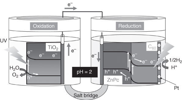
Figure 10.9 Schematic illustration of a two‐compartment cell for unassisted solar water splitting using a TiO2 photoanode and an OSC‐based photocathode.
Amorphous molybdenum sulfide (a‐MoS x ) can be used as an earth‐abundant HER catalyst instead of Pt to develop photocathodes based on the same P3HT/PCBM BHJ [55]. It has been demonstrated recently that a‐MoS x is a coordination polymer based on discrete trinuclear molybdenum disulfide clusters [56]. Photocathodes prepared by the direct spray deposition of mixtures of a‐MoS x and TiO2 on the organic BHJ‐active layer (Figure 10.10) deliver a photocurrent of 200 μA cm−2 at 0 V vs. RHE and up to 300 µA cm−2 at −0.4 V vs. RHE with a 0.6 V anodic shift of the H2 evolution reaction onset potential, a value close to the open‐circuit potential of the P3HT:PCBM solar cell. The presence of TiO2 nanoparticles in the MoS3 film optimises both electron extraction at the PCBM interface and electron transport within the catalytic layer [55], as also observed in other architectures with compact TiO x layer separating the P3HT:PCBM BHJ layer and the catalytic film [57]. Different interfacial layers were investigated to improve the charge transfer between P3HT:PCBM and a‐MoS x . Metallic Al/Ti interfacial layers led to an increase in the photocurrent by up to 8 mA cm−2 at 0 V vs. RHE. A 50‐nm‐thick C60 layer also works as an interfacial layer, with a current density reaching 1 mA cm−2 at 0 V vs. RHE [59]. A common issue is the long‐term stability of the light‐driven activity under operation. In a different architecture, the use of an insoluble cross‐linked PEDOT:PSS hole selective underlayer between the transparent conducting oxide substrate and the P3HT:PCBM BHJ layer proved to be quite efficient to avoid delamination of the organic layer and to allow sustained PEC activity for more than 3 h with faradaic efficiency of 100% in pH 2 aqueous media [57]. Alternatively, reduced graphene oxide, molybdenum, tungsten and nickel oxide underlayers proved efficient for sustained photoelectrochemical activity in acidic aqueous electrolytes [60, 61]. However, photoelectrodes based on P3HT:PCBM BHJ core do not allow to store much energy as the onset potential for H2 evolution is marginally positive with respect to the equilibrium potential of the H+/H2 couple. We then switched to planar p/n heterojunctions of small molecules and oligomers as this technology allows the use of a wider variety of donor and acceptor molecules. The use of α‐sexithiophene (α‐6T) and boron subphthalocyanine chloride (SubPc) as donor and acceptor OSC materials, respectively, in combination with C60 as electron‐extracting layer (Figure 10.10) indeed resulted in a significant increase of both the onset potential and the solar‐to‐hydrogen power saved [59, 60] for H2 evolution of OPV‐based photocathodes [58].
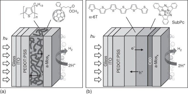
Figure 10.10 Architectures of (a) the P3HT:PCBM/a‐MoS x [57] and (b) SubPc:C60/a‐MoS x [58] H2‐evolving photocathodes.
Source: From Haro et al. [57]. Reproduced with permission of American Chemical Society.
10.2.3 Dye‐sensitised Photocathodes for H2 Production
Dye‐sensitised photocathodes for H2 production are typically composed of three major parts: (i) a semiconductor (SC) layer for charge separation, (ii) a molecular dye for light harvesting and (iii) a catalyst for converting H+ to H2. Upon visible‐light irradiation, two successive electron transfers take place (Figure 10.11): first, hole injection from the excited dye to the semiconductor valence band occurs and generates the reduced dye, which, in turn, transfers the electron to the H2‐evolving catalyst. Obviously, two successive light‐induced cycles are required for hydrogen production to occur.
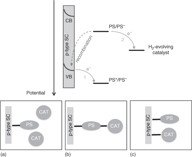
Figure 10.11 Schematic presentation of the electron transfers taking place upon irradiation of a dye‐sensitised photocathode (top) and the three different H2‐evolving photocathode architectures (bottom): physisorbed or diffusing catalyst (a); covalent or supramolecular dye–catalyst assembly (b); co‐grafted dye and catalyst (c).
The development of such H2‐evolving dye‐sensitised photocathodes follows on from the knowledge acquired on p‐type dye‐sensitised solar cells (p‐DSSCs) [62, 63]. Indeed, both systems rely on similar requirements: (i) a p‐type semiconductor fulfilling precise specifications such as transparency in the visible‐light domain, good carrier mobility, porosity to insure a high molecular loading, a valence band potential suitable for electron transfer to a molecular photosensitiser (Figure 10.11); (ii) the robust grafting of molecular photosensitisers onto the surface of the semiconductor and (iii) the choice of an efficient electron acceptor in order to avoid the detrimental recombination of the photoreduced dye with the holes generated in the semiconductor (Figure 10.11). However, two main differences also arise for the construction of H2‐evolving dye‐sensitised photocathodes: first, the final electron acceptor is no more the electrolyte but the H2‐evolving catalyst; as a consequence, the efficiency of the process does not rely anymore on a single electron transfer but on multielectronic catalysis, thus introducing kinetic limitations. Second, the system should operate in aqueous electrolytes, which introduces new constraints both regarding stability and electronics because of the pH dependence of the surface state of the semiconductor. Such additional complexity renders the development of efficient dye‐sensitised H2‐evolving photocathodes more challenging. Most of the systems reported to date are assessed under a three‐electrode configuration using a reference electrode and a Pt counter electrode and not in a complete device. Examples of complete devices, such as tandem‐dye‐sensitised photoelectrochemical cells, are scarce, owing to the difficulty to find suitable working conditions, matching the requirements of both the anode and the cathode activities.
Currently, the range of known transparent and stable p‐type metal oxides that can be prepared from inexpensive materials and by techniques available to most laboratories is limited to NiO [64, 65], CuO [66], CuCrO2 [67, 68], CuAlO2 [68, 69] and CuGaO2 [68, 70]. To date, the majority of reported photocathodes for H2 production rely on NiO [5, 71], the preparation of which has been subject to optimisation for p‐DSSCs [64]. Nonetheless, NiO remains sub‐optimal as a p‐type semiconductor due to low hole mobility, an absence of hole traps and low permittivity [72]. Alternatively, quasi‐metallic oxides such as ITO also proved to be suitable porous materials for the construction of dye‐sensitised photocathodes [73–75].
A wide range of dyes suitable for sensitisation of p‐type semiconductors have been reported in recent years, and some structural prerequisites for good performance have been elucidated, thanks to intensive studies on p‐DSSCs [63]. It is important that the dye offers a large driving force for hole injection and long‐lived charge separation. The former can be optimised by modifying the electronic structure so that the oxidation potential of the dye (HOMO) is significantly more positive than the valence band of the NiO. The latter has been addressed by designing dyes based on a donor acceptor motif [72], also called “push–pull” dyes. The electron‐rich donor moiety (HOMO) is anchored to the NiO, whereas the electron poor acceptor (LUMO) is located away from the NiO, thus disfavouring recombination. The bridge between the two moieties is as long as possible and rigid to avoid bending of the acceptor unit towards the NiO surface. A range of chemical groups are available for anchoring molecules to metal‐oxide surfaces such as carboxylic acid, phosphonic acid, hydroxamic acid and silatranes [76]. Carboxylic and phosphonic acids are commonly utilised.
There is a wide range of molecular catalysts reported for proton reduction to hydrogen, which may be incorporated into a photocathode system. The catalyst may be dissolved in the electrolyte solution (Figure 10.11a) or attached to the electrode surface. In most cases where a catalyst is attached to the surface, it is functionalised with the same anchoring groups as the dyes used in DSSCs (Figure 10.11c). In some molecular systems, the catalyst is covalently attached to the dye and does not require a separate anchoring group (Figure 10.11b). It is desirable that the catalyst operates at a high rate (TOF), with minimal energy requirements (overpotential), and has high stability (turnover number, TON). One of the best performing catalysts for H2 production is Pt. However, Pt is rare and there is not enough in the Earth's crust if all the vehicles in use today were to transition to a hydrogen economy [77], as such there is a large research effort to develop systems that use earth‐abundant elements [9, 78, 79]. This chapter focuses on catalysts using relatively abundant metals and Pt will not be discussed.
10.2.3.1 Dye‐sensitised Photocathodes with Physisorbed or Diffusing Catalysts
One of the earliest examples of a dye‐sensitised photocathode for H2 production was reported in 2012 [80]. An organic dye, denoted P1, well‐established in the field of p‐DSSCs, was used as the sensitiser (Figure 10.12). P1 consists of a triphenylamine (TPA) donor unit, linked to two dicyanovinylene acceptor units via thiophene bridges, and a carboxylate anchoring group. The H2‐evolving photocathode was built by simply dropping a cobaloxime catalyst solution onto the sensitised NiO surface and allowing it to dry. Cyclic voltammetry (CV) indicated that electron transfer from the reduced dye to the catalyst is energetically feasible. Chronoamperometry experiments (−0.4 V vs. Ag/AgCl) were performed under chopped light irradiation (>400 nm) and showed −4 µA photocurrent density with P1 alone compared with −15 µA in the presence of the cobaloxime. H2 production was detected using a modified Clark‐type electrode. In both cases, the photocurrent decays over tens of seconds, but the decay is much faster with the catalyst and this is most probably due to rapid leaching of the cobaloxime into the electrolyte.
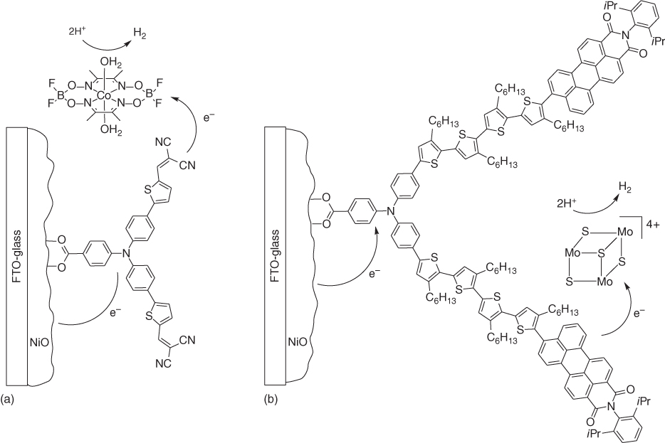
Figure 10.12 Structure of photocathodes based on dye‐sensitised NiO with a physisorbed (a) [80] or a diffusing (b) [81] H2‐evolving catalyst.
Source: From Click et al. [81]. Reproduced with permission of American Chemical Society.
Later in the same year, a photocathode allowing H2 production without any applied bias was reported in conjunction with a photoanode [82]. It consisted of a NiO film sensitised with an organic donor–bridge–acceptor dye, relying on a TPA unit bis‐functionalised with perylene monoimide (PMI) acceptors through sexithiophene bridges. This dye‐sensitised photocathode allows H2 production with unity Faradaic efficiency, without any additional catalyst, which is unprecedented in the field. It produced a stable 3.9 µA cm−2 photocurrent density and up to 0.6% incident photon to current efficiency (IPCE). In a tandem configuration with a BiVO4 photoanode, H2 was produced with 80% Faradaic efficiency without any applied bias. Furthermore, the dye‐sensitised film is stable in HCl and NaOH solutions for days; the observed stability is likely to be the result of the hexyl chains protecting the surface from the solution.
This stability effect was also recently reported for a photocathode sensitised with a related TPA–quaterthiophene–PMI push–pull dye, inspired from the thylakoid membranes of photosystems I and II (Figure 10.12) [81]. The presence of hexyl chains on the organic dye creates a hydrophobic layer over the electrode surface protecting not only NiO from acid dissolution but also the carboxylate anchoring of the dye from surface desorption. As a consequence, the electrode was stable at pH 0, which is the optimal pH for the [Mo3S4]4+ H2‐evolving catalyst present in solution. Under these conditions, the dye‐sensitised photocathode maintained a photocurrent density of −183 µA cm−2 for 17 h at 0 V vs. NHE with a Faradaic efficiency for H2 production of 49%.
An alternative strategy for improving stability is the application of a thin layer of Al2O3 by ALD to prevent dye desorption. In one example, a PMI‐based dye‐sensitised NiO film was protected by 30 ALD cycles of Al2O3 [83]. A further advantage of Al2O3 over layers lies in the insulating properties of Al2O3 that can slow down charge recombination between the reduced dye and the NiO surface (see another example in Ref. [84] described below), as demonstrated with femtosecond transient absorption spectroscopy. The resultant electrode was stable to air and light over 45 days and could be assessed in H2SO4 aqueous solutions. Addition of either a nickel bis(diphosphine) or a cobaloxime H2‐evolving catalyst to the solution gave significant photocurrent enhancement and led to hydrogen production with Faradaic efficiencies of 98% and 60% for the Ni and Co catalysts, respectively. When films without ALD treatment were assessed during 2 h with the Ni catalyst in solution, a lower Faradaic efficiency (80%) was measured and complete loss of the dye was observed, whereas the dye remained intact on ALD‐treated electrodes.
10.2.3.2 Dye‐sensitised Photocathodes Based on Covalent or Supramolecular Dye–Catalyst Assemblies
Reports on supramolecular or covalent dye–catalyst dyad assemblies grafted onto NiO are scarce. In principle, this is advantageous because charge transfer is no longer diffusion‐limited as for catalysts in solution, and the dye and catalyst are not competing for surface sites as occurs for co‐adsorption strategies.
The first example of a H2‐evolving dye–catalyst assembly anchored onto NiO was reported in 2013 [84]. A cyclometalated tris‐heteroleptic ruthenium photosensitiser was employed. The phenylpyridine ligand was anchored to NiO through a carboxylate group and pendant pyridines on the bipyridine ligands were coordinated to a cobaloxime catalyst (Figure 10.13). CV showed that hole injection from the excited Ru dye to NiO and electron transfer from the reduced Ru dye to the cobaloxime (see Figure 10.11) were both energetically favourable. The anchoring shows good stability in water and phosphate buffer (pH 7) attributed to the increased electron density from the phenylpyridine at the carboxylate group. Upon irradiation, the onset potential of the catalytic wave is shifted 40 mV more positive, indicating that solar energy can be stored by the system. The IPCE spectrum matches the absorption spectrum of the dye and is enhanced in the presence of the cobaloxime. A single ALD layer of Al2O3, coated onto NiO before grafting the dye–catalyst assembly, was shown to more than double the photocurrent density; this beneficial effect was attributed to reduced hole–electron recombination across the NiO surface. The photocathode produced 290 nmol H2 with a Faradaic efficiency of 45%, at −0.2 V vs. NHE for 2.5 h (pH 7 phosphate buffer). Shifting the applied bias positive to 0.1 V reduced the unproductive dark current to give a Faradaic efficiency of 68%.
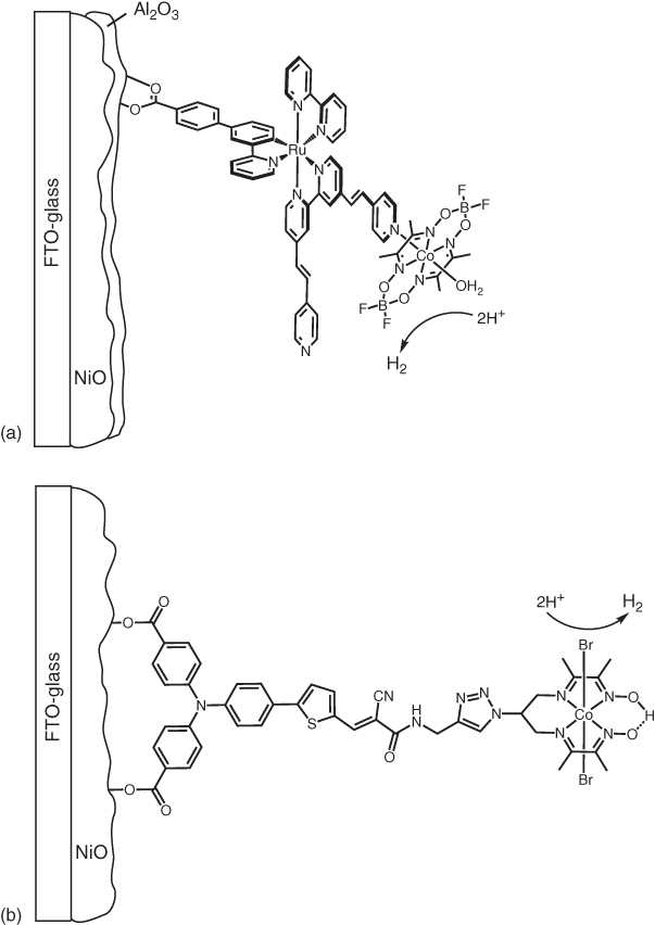
Figure 10.13 Structures of photocathodes based on supramolecular (a) [84] or covalent (b) [85] dye–catalyst assemblies.
Source: (a) From Ji et al. [84]. Reproduced with permission of American Chemical Society. (b) From Kaeffer et al. [85]. Reproduced with permission of American Chemical Society.
The first fully noble metal‐free dyad was composed of a push–pull organic dye covalently attached to a cobalt diimine–dioxime catalyst by a copper‐catalysed azide–alkyne cycloaddition (“click” chemistry) (Figure 10.13) [85]. It was demonstrated that the dye could transfer electrons to the Co catalyst both on thermodynamic grounds and by the observation of the photoaccumulation of Co(I) under visible‐light irradiation in the presence of triethanolamine (TEOA) as electron donor. In MES buffer (pH 5.5) at 0.14 V vs. RHE, a photocurrent of −15 µA cm−2 was observed, and H2 was produced with a Faradaic efficiency of 10%.
In 2016, a layer‐by‐layer strategy was reported to construct a H2‐evolving photocathode based on a [Ru(bpy)3]2+ derivative photosensitiser and a nickel bis(diphosphine) catalyst. Both of them are functionalised by phosphonic acid groups to allow a covalent anchoring of the Ru dye onto NiO and the chelation of Zr4+ cations (Figure 10.14a) [86]. The assembly was built through a step‐by‐step procedure, the NiO surface being first covered by a monolayer of phosphonated photosensitiser, before soaking in a ZrOCl2 solution, and finally in the phosphonic-acid-substituted catalyst solution. The best performing electrode was constructed with one layer of the phosphonic acid functionalised [Ru(bpy)3]2+ and two layers of Ni catalyst. It displayed a photocurrent of −9 µA cm−2 at 0.3 V vs. RHE and a Faradaic efficiency for H2 production of 10%. Post‐photoelectrocatalysis characterisation of the electrode showed that no Ru was lost from the surface. The Ni catalyst was harder to detect due to the underlying NiO dominating XPS or inductively coupled plasma‐optical emission spectrometry (ICP‐OES) measurements. However, the CV of the electrode was unchanged after photoelectrolysis, suggesting little modification of the surface composition.

Figure 10.14 Structure of H2‐evolving dye‐sensitised photocathodes based on layer‐by‐layer fabricated supramolecular dye–catalyst assemblies [75, 86].
Source: From Gross et al. [86]. Reproduced with permission of Royal Society of Chemistry.
The following example is conceptually very similar to the previous one but relies on a conducting inverse opal nanostructured ITO electrode material (Figure 10.14b) [75]. Additionally, a phosphonic acid‐substituted dianiline (DA) was inserted between NiO and the Ru photosensitiser to provide longer‐lived charge separation, as confirmed with nanosecond transient absorption measurements: for the ITO‐DA‐Zr‐RuP2 2+ assembly in the absence of catalyst, a long‐lived signal at 510 nm characteristic for the reduced dye is observed, in agreement with hole injection into ITO. For the assembly including NiP, this signal can still be observed but with a lower yield, indicative of electron transfer to the catalyst within the first 50 ns of the experiment. Under photoelectrocatalytic conditions, the photocathode produced H2 with 53% Faradaic efficiency and with a quantum yield of 0.85%, in MES buffer pH 5.1 at an applied potential of −0.25 V vs. NHE.
10.2.3.3 Dye‐sensitised Photocathodes Based on Co‐grafted Dyes and Catalysts
Co‐grafting dye and catalyst onto the electrode is an appealing alternative to covalent assembly of the two components, which often requires tedious synthetic steps. This strategy relies on electron hopping from the reduced dye to the catalyst on the surface for hydrogen production to occur. However, in sharp contrast with photoinduced intramolecular electron transfer processes within dyad assemblies, this process remained underexplored until the recent studies by the group of L. Hammarström. The first demonstration of electron hopping between molecules on NiO was reported in 2012 [87]. The dye used was Coumarin‐343 due to its high reduction potential and fast hole injection into NiO. The selected catalyst was a derivative of a known Fe phosphine complex (Fe1), reported to produce H2 with a TOF of 10 000 s−1 (Figure 10.14a). The radical anion of Fe1 could be observed within the 50 ns time resolution of the equipment and the charge recombined with holes in NiO over 100 µs. Interestingly, these processes were unaffected by the dyeing order of the dye and catalyst. In the absence of Fe1, no signals were observed on the nanosecond timescale, in agreement with the previously reported femtosecond hole injection from dye to NiO followed by recombination on the picosecond timescale. To rationalise these data, it is postulated that electrons migrate across the surface via a sub‐nanosecond self‐exchange mechanism between dye molecules. Due to low mobility in NiO, holes are localised; this self‐exchange mechanism may thus transport the electrons away from the holes to Fe1, explaining the nanosecond lifetime for the Fe1 anion despite dye–NiO charge recombination occurring on the picosecond timescale.
Four years later, the photoinduced dynamics of C343 on NiO was investigated with a different catalyst, a Fe carbonyl benzene dithiolate complex (Fe2 in Figure 10.15a) [88]. For co‐adsorbed C343 and Fe2, hole injection is observed from C343 to NiO on c. 200 fs timescale, as for C343 alone. However, for C343 alone, the reduced dye lifetime is hundreds of picoseconds, whereas with Fe2 the reduced C343 has a half‐life of 10 ps. In this case, the neutral dye signal recovers and the reduced catalyst signature is observed and persists for up to 30 µs. The electron transfer from dye to catalyst is three orders of magnitude faster than ‘hole‐hopping’ observed on TiO2 [92, 93], and this may be due to the large driving force for electron transfer from dye to catalyst in this case. Unreactive C343 anion cannot be observed, suggesting that there are no dye molecules unable to transfer electrons to Fe2, either directly or by rapid hopping from dye to dye.
![Schematic structure of the photoinduced dynamics of C343 on NiO investigated with a different catalyst, a Fe carbonyl benzene dithiolate complex employed for the construction of co-grafted H2-evolving photocathodes.; Schematic structure of the well-known [Ru(bpy)3]2+dye in combination with a cobaloxime catalyst employed for the construction of co-grafted H2-evolving photocathode.; Schematic structure of the P1 dye and a cobaloxime catalyst employed for the construction of co-grafted H2-evolving photocathode.](http://images-20200215.ebookreading.net/4/1/1/9783527341634/9783527341634__molecular-technology-volume__9783527341634__images__c10f015.jpg)
Figure 10.15 Dyes and catalysts employed for the construction of co‐grafted H2‐evolving photocathodes.
Source: (a) From Ref. [87–89]. (b) From Ref. [90]. (c) From Li et al. [91]. Reproduced with permission of American Chemical Society.
Fe2 showed poor binding to NiO and to improve on this, a novel catalyst was prepared with a phosphonate anchoring group (Fe3 in Figure 10.15a) [89]. Transient absorption spectroscopy of C343 on NiO (λ exc = 440 nm) shows hole injection in <150 fs, in agreement with the previous work, and charge recombination over 9 ps. A co‐sensitised sample of C343 and Fe3 on NiO shows quite different kinetics. Hole injection is similar to C343 alone, but the signal for the C343 anion decays much faster and via several processes between 1 and 1000 ps. A signal corresponding to reduced Fe3 can be observed from 1 ps and persists for >2 ns. The decay of the C343 anion is assigned to the reduction of Fe3, and therefore, this reduction occurs via a combination of different processes. However, the reduction of Fe3 mostly takes place between 1 and 10 ps and with an electron transfer yield of 70%. This electron transfer occurs more quickly and in greater yields than previously observed for C343 with Fe2, and this may be related to the flexibility of the linking group. C343 co‐grafted with Fe3 on NiO was measured on a longer timescale in order to elucidate the fate of the reduced Fe3. The signal assigned to reduced Fe3 decays via multiple processes with time constants from ∼2 µs to >10 ms. The longer components, which outcompete the lifetime of reduced Fe2, are again attributed to the flexible linker in Fe3. Lifetimes of tens of milliseconds are important as protonation of the reduced Fe3 is expected to occur on the millisecond timescale. Indeed, the system produced H2 (acetate buffer pH 4.5, −0.3 V vs. Ag/AgCl) with a Faradaic efficiency of 50% and a photocurrent of −10 µA cm−2. IR spectroscopy showed that deactivation is, at least in part, due to the loss of the CO ligands and desorption of Fe3 from the surface, whereas the C343 is quite stable.
A photoelectrode was assembled with a bis‐phosphonate derivative of the well‐known [Ru(bpy)3]2+ dye in combination with a cobaloxime catalyst possessing a pyridine dicarboxylate anchoring group (Figure 10.15b) [90]. Under a bias of −0.4 V vs. Ag/AgCl, a cathodic photocurrent of −13 µA cm−2 was observed. Hydrogen production was not quantified, but the photocathode was combined with a molecular photoanode under a two‐electrode configuration. The tandem cell produced greater photocurrent than the photocathode alone but less than the photoanode alone, indicating that the photocathode activity is limiting the device performance.
Another example of a co‐grafted photocathode was prepared with CdSe QDs as the light absorber combined with a cobaloxime catalyst [119]. The QDs were capped with thioglycolic acid, which provides a carboxylate function for grafting onto NiO, whereas the cobaloxime contained a phosphonate anchoring group. The electrode was constructed from an open porous NiO structure where nanoflakes were grown from a nickel nitrate precursor, in order to have a high surface area and promote high loadings of sensitiser and catalyst. Indeed, when co‐grafted with QDs and cobaloxime, the photocurrent density was 1.7 times greater when compared with a classical doctor‐bladed NiO preparation. The electrode displayed stable photocurrents up to 110 µA cm−2 at 0 V vs. NHE in neutral aqueous solution and produced hydrogen with 81% Faradaic efficiency. When a cobaloxime without a phosphonate anchoring group was used, the photocurrent rapidly decayed to 66 µA cm−2, thus highlighting the benefit of co‐grafting the catalyst. Other QDs/NiO‐based photoelectrodes have been prepared with deposited MoS x catalyst [94] or molecular cobalt dithiolene catalyst in solution [95].
In 2015, a tandem water‐splitting cell was reported based on molecular dyes and catalysts [91]. The photocathode consisted of the P1 dye and a cobaloxime catalyst, functionalised with an alkyl–phosphonate anchoring group, co‐adsorbed onto NiO (Figure 10.15c). The photocathode displayed a photocurrent of −45 µA cm−2 on the timescale of the linear scan voltammetry (LSV) at applied potentials <−0.1 V vs NHE. This dropped to −20 µA cm−2 at longer times. Hydrogen production was confirmed with a Faradaic efficiency of 68%. The photocathode was integrated into a tandem cell with a photoanode composed of an organic dye and a Ru‐based water oxidation catalyst co‐adsorbed onto TiO2. The tandem cell gave a Faradaic efficiency of 55% for H2 without any applied potential and a solar to hydrogen efficiency of 0.05%. In one example of a molecular photocathode not using NiO, a [Ru(bpy)3]2+ derivative with pendant pyrrole groups was polymerised onto a carbon electrode, followed by electrodeposition of MoS x [96]. The electrode gave a photocurrent of −25 µA cm−2 with an applied bias of 0.1 V vs Ag/AgCl at pH 0.3. Under these conditions, H2 was produced with 98% Faradaic efficiency. In terms of the quantity of MoS x , a TON of 31 was obtained, equating to a TOF of 16 h−1.
Proof of concept for dye‐sensitised H2‐evolving photocathodes has been made in the last 5 years. However, low current density and poor durability remain as major challenges. A commercial device should perform efficiently for many months or years and yet most reports detail activity on the scale of hours.
10.3 Photocathodes for CO2 Reduction Based on Molecular Catalysts
The reduction of CO2 to obtain high‐energy compounds has attracted much attention as one of the key technologies for addressing serious issues such as global warming and shortages in energy and carbon resources. Since the famous report from Lehn and coworkers about the highly selective reduction of CO2 to CO using fac‐Re(bpy)(CO)3Cl as an electrocatalyst [97] as well as a photocatalyst [98], many types of molecular (photo)catalysts have been intensively developed [99]. For example, metal complexes of Re(I), Ru(II), Co(II), Ni(II), Mn(I) and Fe(II) and some pyridine derivatives have been proposed as potential catalysts for electrochemical and photochemical systems. In this section, some of the successful photoelectrochemical CO2 reduction systems using molecular catalysts or molecular photocatalysts combined with electrodes are introduced.
10.3.1 Photocatalytic Systems Consisting of a Molecular Catalyst and a Semiconductor Photoelectrode
As already mentioned in the section about H2 evolution, semiconductors with a narrow bandgap can absorb visible light, and it is expected that a combined system with molecular electrocatalysts will be useful even for selective CO2 reduction (Figure 10.16).
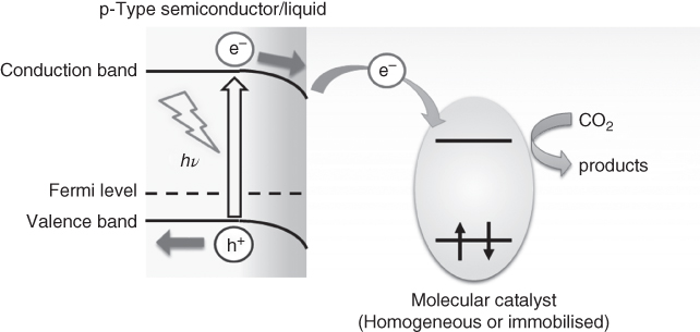
Figure 10.16 Schematic of CO2 reduction using a combination of a molecular catalyst and a semiconductor photoelectrode.
In the initial stage of the studies, combinations of semiconductor photoelectrodes with solutions containing a molecular electrocatalyst were developed for CO2 reduction. A current was obtained at potentials more positive than those of the theoretical redox potentials under irradiation of the semiconductor photoelectrodes. This indicated that the catalytic reduction reaction at the molecular catalyst progressed by utilisation of highly reducing conduction band electrons that were produced by photoexcitation of the semiconductor photoelectrodes. It was reported that macrocyclic NiII and CoII complexes were found to be good electrocatalysts for CO2 reduction to CO with p‐Si (1.1 eV) [100, 101], p‐GaAs (1.4 eV) [102] and p‐GaP (2.2 eV) [103] photoelectrodes. Recently, Kubiak and coworkers examined in detail a photoelectrochemical system using p‐Si as a semiconductor photoelectrode and Re(bpy‐Bu t )(CO)3Cl (bpy‐Bu t = 4,4′‐di‐tert‐butyl‐2,2′‐bipyridine, Figure 10.17a) as a molecular catalyst for CO2 reduction to CO [106]. Briefly, when the p‐Si electrode was selectively photoexcited (λ ex = 661 nm) in an Ar atmosphere in acetonitrile containing the Re complex and a supporting electrolyte, the potential of the reduction of the Re complex shifted in the positive direction by ∼500 mV compared with that of the corresponding reaction using a platinum electrode. Under a CO2 atmosphere, the system afforded CO with a Faraday efficiency of 97% ± 3%, and its quantum efficiency for light‐to‐chemical energy conversion reached 61%. An interesting feature of this system was that direct hydrogen production from the p‐Si electrode surface could be controlled by the addition of water and variation of the concentration of the molecular catalyst, which afforded control of the CO/H2 production ratio [107]. Fe [108] and Mn [109] complexes combined with silicon‐based photoelectrodes were also successfully applied as molecular catalysts for CO2 reduction.

Figure 10.17 Structures of Re molecular catalyst (a) utilised in Ref. [103] and Ru catalysts with pyrrole (b) and phosphonate groups (c) used in Refs [104, 105].
Source: Schreier et al. [104]. https://www.nature.com/articles/ncomms8326. Licensed under CC BY 4.0.
Immobilisation of molecular electrocatalysts on semiconductor electrodes was examined with respect to efficient electron injection from the photoexcited electrode to the electrocatalyst. Grätzel and coworkers recently reported a CO2 reduction system using polycrystalline Cu2O in the form of a p‐type semiconductor decorated with a Re(bpy)CO3Cl molecular catalyst with a phosphonate anchoring unit (Figure 10.18) [110]. The photocathode was prepared by electrodeposition of Cu2O followed by sequential modification with 20 nm of Al‐doped ZnO (AZO) and 100 nm of TiO2 by ALD [111]. Cu2O is generally photoelectrochemically unstable; however, decomposition of the Cu2O electrode was effectively suppressed by protecting the surface with a TiO2 layer, whereas the AZO layer between these acted as an n‐type buffer layer for constructing a p–n junction with the Cu2O layer, thereby enhancing charge separation. Moreover, they synthesised a mesoporous scaffold with a thickness of 4.5–5 µm with 18 nm TiO2 particles on the surface of the flat photoelectrode in order to support a sufficient amount of the Re catalyst. Photoelectrochemical measurements revealed that this photoelectrode generated substantial photocurrents exceeding 2.5 mA cm−2 under simulated sunlight in a CO2‐purged acetonitrile solution containing 0.1 M tetrabutylammonium hexafluorophosphate as an electrolyte. The mesoporous scaffold gave a 40‐fold increase in current compared with that of the flat photocathode. Control experiments were performed in the absence of Cu2O and light. Six hundred millivolt more negative potential was required to observe catalytic current when a mesoporous layer of TiO2 on FTO was used as the electrode. This indicates that the photovoltage was produced by photoexcitation of the Cu2O layer. Notably, both the photocurrent and obtained photovoltage showed an improvement over a previously reported system that used a TiO2/AZO/Cu2O photoelectrode in an acetonitrile solution containing a dissolved Re molecular catalyst (2.1 mA cm−2 and 560 mV) [104]; that is, the immobilisation of the molecular catalyst on the photoelectrode surface resulted in enhancement of the photoelectrochemical activity for CO2 reduction. They suggested the following reasons for this: (i) electron transfer from the semiconductor electrode to the catalyst immobilised on the electrode surface should be more efficient compared to that in the combined system of the photocathode with the homogeneous Re catalyst in solution; (ii) immobilisation of the Re catalyst on the high surface area of the mesoporous TiO2 scaffold could decrease light absorption by the catalyst, that is, the so‐called inner filter effect, resulting in effective formation of photogenerated electrons on the photocathode. The system displayed >80% Faradaic efficiency for CO generation from CO2 in the first hour, although the photocurrent gradually decreased. The authors noted the possibility of catalyst deactivation on the electrode, which was possibly caused by structural changes in the bipyridine ligand of the Re catalyst.
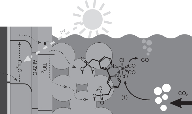
Figure 10.18 Protected Cu2O photoelectrode with covalently bound Re(I) CO2 reduction catalyst.
Source: Schreier et al. [110]. Reprinted with permission of American Chemical Society.
Aiming to couple CO2 reduction with water oxidation, Morikawa, Sato and colleagues immobilised a Ru complex polymer ([Ru(N^N)(CO)2] n , RCP, N^N = diimine ligand) as a catalyst layer on a zinc‐doped indium phosphide photoelectrode (InP–Zn, E g = 1.35 eV) [105]. This polymer was synthesised from the monomer shown in Figure 10.17b by photoelectrochemical polymerisation using the InP–Zn photoelectrode. Ru−Ru bonds were formed by a reductive reaction using electrons generated by photoexcitation of the InP–Zn photoelectrode, and then the pyrrole groups were oxidatively polymerised by anodic polarisation. This method was originally developed by Deronzier and coworkers [112]. The RCP‐modified p‐InP–Zn electrode generated a cathodic photocurrent under visible‐light irradiation in a CO2‐purged aqueous solution, and the onset potential was 0.8 V more positive than that of the dark cathodic current. The formation of formic acid as a product of CO2 reduction was confirmed using the RCP‐modified InP–Zn photocathode at a potential of −0.6 V vs Ag/AgCl under visible light (λ > 400 nm), and the Faradaic efficiency was 62.3%. These results suggest that photoexcited electrons in the conduction band of InP–Zn transferred to the RCP, resulting in subsequent reduction of CO2 by the reduced RCP. Notably, the photocathode with the RCP, which was prepared by cathodic polymerisation only, showed only 34.3% of the current efficiency for formate formation. The authors noted that the two‐step polymerisation that formed the polypyrrole structure reinforced the contact between the RCP and p‐InP–Zn, resulting in a higher Faradaic efficiency. They also pointed out the possibility of the formation of gaseous products, for example, CO and H2, as the reason for the decrease in the Faradaic efficiency, whereas no detailed analysis of the gas phase component was performed. They subsequently reported a photocathode using Cu2ZnSnS4 (CZTS, E g = 1.5 eV) as a p‐type semiconductor, which consists of abundant and relatively cheap elements, with the same RCP catalyst [113]. CZTS modified with the RCP exhibited a much higher cathodic photocurrent than unmodified CZTS in CO2‐purged water, which suggests that the photoexcited electrons in CZTS were transferred to the RCP during the CO2 reduction reaction. Furthermore, both a higher photocurrent and production of formic acid were obtained by adding an equimolar amount of a Ru complex with phosphonate groups as anchor (Figure 10.17c) in the polymerisation process on the photocathode. The authors suggested that stronger contact with the RCP on the photoelectrode could be obtained by chemisorption of the phosphonate anchors, and thus a higher activity for CO2 reduction was achieved. A photoelectrode in which S was partially substituted by Se (Cu2ZnSn(S,Se)4 – CZTSSe) was combined with the RCP. The photocurrent and formic acid generation were improved due to higher hole conductivity obtained by Se substitution. In both systems using CZTS and CZTSSe‐based photocathodes, the Faradaic efficiencies were ∼80%.
Morikawa and coworkers successfully applied these photocathodes with an n‐type semiconductor photoanode, which could use water as an electron source for the reduction of CO2. The reaction proceeded via step‐by‐step excitation of both semiconductor electrodes, known as a Z‐scheme‐type electron transfer, using simulated solar light containing UV wavelengths. When the RCP‐modified semiconductor photocathodes were used for CO2 reduction, the valence bands of the semiconductors of the photocathodes were too ‘shallow’; that is, they were more negative compared with the redox potential of water oxidation, and thus this reaction could not take place at the counter electrode without applying an external bias. To solve this problem, they utilised oxide‐based n‐type semiconductor electrodes (either TiO2 or SrTiO3) as the photoanode for water oxidation (Figure 10.19). First, a photoelectrochemical cell consisting of an RCP/InP–Zn photocathode and a Pt/TiO2 photoanode was assembled [114]. The electrodes were partitioned by a Nafion film, and CO2 and Ar were introduced into the cathodic and anodic sides, respectively. The cell was then irradiated with simulated sunlight (AM 1.5) from the anode side without bias. The TiO2 absorbed only the UV light and the InP–Zn absorbed the remaining light transmitted through the photoanode. Formic acid was generated linearly from the cathodic side and, at the same time, oxygen was formed at the anodic side. Isotopic labelling experiments clearly indicated that formic acid and oxygen were derived from CO2 and water, respectively. In this system, the conduction band edge potential of TiO2 was 0.5 V more negative than the valence band edge potential of InP. Thus, photogenerated electrons in the conduction band of TiO2 could move to the valence band of the excited InP through the outer circuit, resulting in Z‐scheme‐type electron transfer. The efficiency of the conversion of sunlight energy to chemical energy was 0.03%.
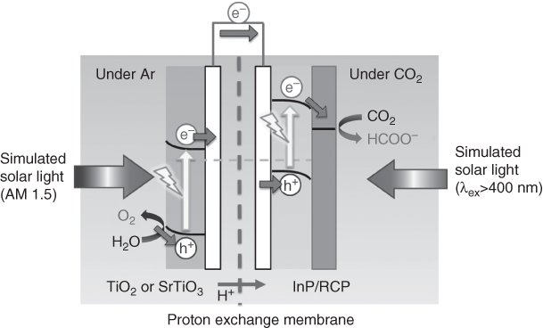
Figure 10.19 Schematic of the photoelectrochemical cell for tandem CO2 reduction and water oxidation comprising a RCP/InP–Zn photocathode and metal‐oxide photoanodes.
The same group achieved much higher energy conversion efficiency by changing the photoanode from TiO2 to SrTiO3 [115]. As the bandgap of SrTiO3 (3.2 V) is larger than that of TiO2 (3.0 eV), shorter wavelengths of light would be absorbed. The SrTiO3 photoanode generated an anodic photocurrent at a much more negative potential compared with that of the TiO2 electrode, which indicated that the conduction band potential of SrTiO3 was located at a more negative potential than that of TiO2, and the driving force of electron transfer to the photocathode increased. The photocurrent generated from the photoelectrochemical cell using SrTiO3 and RCP/InP–Zn was seven times higher than that from the cell using the TiO2 photoanode, and the energy conversion efficiency reached 0.14%.
The same group also reported a monolithic stand‐alone device composed of an amorphous Si/SiGe triple junction tandem photovoltaic cell and the RCP catalyst. This system was highly active for the reduction of CO2 to HCOOH with 4.6% energy conversion efficiency, where the RCP catalyst was separated from the light absorber (the photovoltaic) with a carbon cloth substrate [116].
10.3.2 Dye‐sensitised Photocathodes Based on Molecular Photocatalysts
The use of molecular photocatalysts immobilised on electrodes for CO2 reduction is attractive because the molecular structure may be tuned in order to optimise redox properties. They can also display high catalytic efficiency and selectivity for CO2 reduction. As is the case for the H2‐evolving photoelectrodes described in Section 10.2.2, molecular photocatalysts need to be fixed to a p‐type semiconductor electrode (e.g. NiO) to drive CO2 reduction with irradiation and using electrons injected from the valence band of the semiconductor (Figure 10.20).

Figure 10.20 Schematic of CO2 reduction using a molecular photocatalyst immobilised on a semiconductor electrode.
In 2014, Inoue and colleagues reported a system in which a supramolecular photocatalyst composed of a zinc porphyrin sensitiser and a Re catalyst unit (Figure 10.21a) was immobilised on NiO with carboxylic groups as anchors [6]. This supramolecular photocatalyst strongly absorbs visible light, which is attributed to the Soret band of the Zn porphyrin at 430 nm. They first demonstrated the photocatalytic activity of this system under irradiation with visible light (λ ex = 430 nm) in a DMF–triethylamine (TEA, 4 : 1, v/v) mixed solution. The TON of CO formation and the quantum yield were 14% and 0.12%, respectively. They then examined the immobilisation of the supramolecular complex on NiO in order to perform photoelectrochemical CO2 reduction. The fluorescence lifetimes (τ) of both the Zn porphyrin mononuclear complex and the supramolecular complexes immobilised on NiO were shortened to about 30 ps from that in solution (τ < 2 ns), which suggested efficient electron injection from NiO to the excited state of the Zn porphyrins. Nanosecond laser flash photolysis experiments showed the formation of a radical anion of the Zn porphyrins with a lifetime of 180 ns. CO2 reduction was performed using the photoelectrode with the Zn porphyrin–Re supramolecular photocatalyst in CO2‐saturated DMF solution containing tetrabutylammonium hexafluorophosphate (0.1 M) as a supporting electrolyte under irradiation at λ ex = 430 nm. This gave CO as a main product and a TON of 10 based on the immobilised complex, although the Faradaic efficiency was only 6.2%. An alternative photocathode, which was prepared by co‐adsorption of the supramolecular complex with Zn porphyrin as an additional photosensitiser at a ratio of 24 : 1 (mononuclear sensitiser: supramolecular sensitiser), gave a TON of 122 based on the Re catalyst unit. This result was believed to imply that electrons are concentrated in the Re complex unit in the supramolecular photocatalyst by electron hopping between molecules.

Figure 10.21 Structures of the supramolecular photocatalysts comprising a zinc porphyrin (a, [115]) or Ru(II) (b, [7, 116]) sensitiser and a Re(I) catalyst unit with carboxylic or methylphosphonate groups as anchors.
Ishitani and colleagues employed a supramolecular photocatalyst, which consisted of a Ru(II) photosensitiser and a Re(I) catalyst with methylphosphonate groups as anchors (RuRe, Figure 10.21b), for photoelectrochemical CO2 reduction by immobilisation on a NiO electrode [7]. This photocatalyst showed high activity for CO2 reduction in an aqueous solution (quantum yield for CO formation = 13%, TON = 130) [117] as well as in organic solvent. As the valence band edge potential of NiO was more negative than the reduction potential of the excited state of the Ru photosensitiser unit, electron transfer from NiO to the light‐absorbing Ru complex was expected to proceed. This process was clearly observed as a cathodic photocurrent when using a model mononuclear Ru complex on NiO in acetonitrile electrolyte (0.1 M Et4NBF4) under irradiation by visible light, which selectively excites the Ru complex. CO2 reduction was examined using the photoelectrode modified with RuRe at an applied potential of −1.2 V vs. Ag/AgNO3 in a DMF–TEOA (5 : 1, v/v) mixed solution. A cathodic photocurrent and corresponding selective CO generation were observed, and the TON of CO formation based on immobilised RuRe was 32 after 22 h irradiation. This photoelectrode was later successfully employed for CO2 reduction in an aqueous solution [118]. In a CO2‐purged aqueous solution containing 50 mM NaHCO3 (pH = 6.6), a photocathodic response was clearly observed under irradiation at λ ex = 460 nm, where only RuRe was photoexcited. The photoelectrode was irradiated for 12 h with an applied bias of −0.7 V vs. Ag/AgCl, giving 361 nmol of CO (TONCO = 32 based on the amount of RuRe adsorbed on the NiO electrode). Although a small amount of H2 was produced as a by‐product, the total selectivity of CO formation was 91%. This photocathode was then successfully combined with a CoO x /TaON photoanode, which was reported as an efficient photoanode for water oxidation under visible‐light irradiation, in a functional photoelectrochemical cell (Figure 10.22). This cell produced 79 nmol of CO with a small amount of H2 (6 nmol) and O2 (77 nmol) from the photocathode and photoanode, respectively. The cell was operated under visible‐light irradiation (λ ex > 400 nm) with an applied electrical bias of 0.3 V and a chemical bias of 0.10 V originating from the pH difference between the electrolytes for each electrode. The light energy conversion efficiency of the reaction was 1.6 × 10⁻⁵, considering the electrical and chemical bias. This is the first example of a visible‐light‐driven CO2 reduction system using water as the reductant, based on molecular photocatalysts hybridised with semiconductor photocatalysts.

Figure 10.22 Schematic of hybrid photoelectrochemical cell comprising the NiO–RuRe photocathode and CoO x /TaON photoanode [118].
Acknowledgements
This work was supported by the French National Research Agency (Labex program, ARCANE, ANR‐11‐LABX‐0003‐01 and Joint JST‐ANR project PhotoCAT, ANR 14 JTIC 0004 01).
References
- 1 Vesborg, P.C.K. and Jaramillo, T.F. (2012). RSC Adv. 2: 7933–7947.
- 2 Lewis, N.S. and Nocera, D.G. (2007). Proc. Natl. Acad. Sci. U. S. A. 104: 20142–20142.
- 3 Ashford, D.L., Gish, M.K., Vannucci, A.K. et al. (2015). Chem. Rev. 115: 13006–13049.
- 4 Yu, Z., Li, F., and Sun, L. (2015). Energy Environ. Sci. 8: 760–775.
- 5 Queyriaux, N., Kaeffer, N., Morozan, A. et al. (2015). J. Photochem. Photobiol. C 25: 90–105.
- 6 Kou, Y., Nakatani, S., Sunagawa, G. et al. (2014). J. Catal. 310: 57–66.
- 7 Sahara, G., Abe, R., Higashi, M. et al. (2015). Chem. Commun. 51: 10722–10725.
- 8 Ager, J.W., Shaner, M.R., Walczak, K.A. et al. (2015). Energy Environ. Sci. 8: 2811–2824.
- 9 Coutard, N., Kaeffer, N., and Artero, V. (2016). Chem. Commun. 52: 13728–13748.
- 10 Goetzberger, A., Hebling, C., and Schock, H.‐W. (2003). Mater.Sci. Eng. R Rep. 40: 1–46.
- 11 Navarro, R.M., del Valle, F., Villoria de la Mano, J.A. et al. (2009). Photocatalytic water splitting under visible light: concept and catalysts development. In: Advances in Chemical Engineering (ed. I.d.L. Hugo and R. Benito Serrano), 111–143. Academic Press.
- 12 Nann, T., Ibrahim, S.K., Woi, P.‐M. et al. (2010). Angew. Chem. Int. Ed. 49: 1574–1577.
- 13 Chandrasekaran, S., Nann, T., and Voelcker, N. (2016). Nanomaterials 6: 144.
- 14 Chandrasekaran, S., Macdonald, T.J., Mange, Y.J. et al. (2014). J. Mater. Chem. A 2: 9478–9481.
- 15 Chandrasekaran, S., Vijayakumar, S., Nann, T., and Voelcker, N.H. (2016). Int. J. Hydrogen Energy 41: 19915–19920.
- 16 Chandrasekaran, S., McInnes, S.J.P., Macdonald, T.J. et al. (2015). RSC Adv. 5: 85978–85982.
- 17 Chandrasekaran, S., Macdonald, T.J., Gerson, A.R. et al. (2015). ACS Appl. Mater. Interfaces 7: 17381–17387.
- 18 Hou, Y., Abrams, B.L., Vesborg, P.C.K. et al. (2012). J. Photon. Energy 2, 026001‐026001‐026001‐026016.
- 19 Hou, Y.D., Abrams, B.L., Vesborg, P.C.K. et al. (2011). Nat. Mater. 10: 434–438.
- 20 Moore, G.F. and Sharp, I.D. (2013). J. Phys. Chem. Lett. 4: 568–572.
- 21 Le Goff, A., Artero, V., Jousselme, B. et al. (2009). Science 326: 1384–1387.
- 22 Huan, T.N., Jane, R.T., Benayad, A. et al. (2016). Energy Environ. Sci. 9: 940–947.
- 23 Seo, J., Pekarek, R.T., and Rose, M.J. (2015). Chem. Commun. 51: 13264–13267.
- 24 Khusnutdinova, D., Beiler, A.M., Wadsworth, B.L. et al. (2017). Chem. Sci. 8: 253–259.
- 25 Seger, B., Herbst, K., Pedersen, T. et al. (2014). J. Electrochem. Soc. 161: H722–H724.
- 26 Gu, J., Yan, Y., Young, J.L. et al. (2016). Nat. Mater. 15: 456–460.
- 27 Kim, H.J., Seo, J., and Rose, M.J. (2016). ACS Appl. Mater. Interfaces 8: 1061–1066.
- 28 Mueller‐Westerhoff, U.T. and Nazzal, A. (1984). J. Am. Chem. Soc. 106: 5381–5382.
- 29 Cedeno, D., Krawicz, A., and Moore, G.F. (2015). Interface Focus 5: 20140085.
- 30 Krawicz, A., Yang, J., Anzenberg, E. et al. (2013). J. Am. Chem. Soc. 135: 11861–11868.
- 31 Krawicz, A., Cedeno, D., and Moore, G.F. (2014). Phys. Chem. Chem. Phys. 16: 15818–15824.
- 32 Beiler, A.M., Khusnutdinova, D., Jacob, S.I., and Moore, G.F. (2016). Ind. Eng. Chem. Res. 55: 5306–5314.
- 33 Beiler, A.M., Khusnutdinova, D., Jacob, S.I., and Moore, G.F. (2016). ACS Appl. Mater. Interfaces 8: 10038–10047.
- 34 Cedeno, D., Krawicz, A., Doak, P. et al. (2014). J. Phys. Chem. Lett. 5: 3222–3226.
- 35 Baffert, C., Artero, V., and Fontecave, M. (2007). Inorg. Chem. 46: 1817–1824.
- 36 Artero, V., Chavarot‐Kerlidou, M., and Fontecave, M. (2011). Angew. Chem. Int. Ed. 50: 7238–7266.
- 37 Thompson, B.C. and Frechet, J.M.J. (2008). Angew. Chem. Int. Ed. 47: 58–77.
- 38 Green, M.A., Emery, K., Hishikawa, Y. et al. (2015). Prog. Photovolt. Res. Appl. 23: 1–9.
- 39 Sariciftci, N.S., Smilowitz, L., Heeger, A.J., and Wudl, F. (1992). Science 258: 1474–1476.
- 40 Chen, S.N., Heeger, A.J., Kiss, Z. et al. (1980). Appl. Phys. Lett. 36: 96–98.
- 41 Kaneko, M., Okuzumi, K., and Yamada, A. (1985). J. Electroanal. Chem. 183: 407–410.
- 42 Genies, E.M. and Lapkowski, M. (1988). Synth. Met. 24: 69–76.
- 43 Glenis, S., Tourillon, G., and Garnier, F. (1984). Thin Solid Films 122: 9–17.
- 44 El‐Rashiedy, O.A. and Holdcroft, S. (1996). J. Phys. Chem. 100: 5481–5484.
- 45 Suppes, G., Ballard, E., and Holdcroft, S. (2013). Polym. Chem. 4: 5345–5350.
- 46 Li, C., Liu, M., Pschirer, N.G. et al. (2010). Chem. Rev. 110: 6817–6855.
- 47 Lanzarini, E., Antognazza, M.R., Biso, M. et al. (2012). J. Phys. Chem. C 116: 10944–10949.
- 48 Abe, T., Tobinai, S., Taira, N. et al. (2011). J. Phys. Chem. C 115: 7701–7705.
- 49 Haro, M., Solis, C., Blas‐Ferrando, V.M. et al. (2016). ChemSusChem 9: 3062–3066.
- 50 Abe, T., Chiba, J., Ishidoya, M., and Nagai, K. (2012). RSC Adv. 2: 7992–7996.
- 51 Abe, T., Fukui, K., Kawai, Y. et al. (2016). Chem. Commun. 52: 7735–7737.
- 52 Abe, T., Nagai, K., Kabutomori, S. et al. (2006). Angew. Chem. Int. Ed. 45: 2778–2781.
- 53 Abe, T., Taira, N., Tanno, Y. et al. (2014). Chem. Commun. 50: 1950–1952.
- 54 Abe, T., Tanno, Y., Taira, N., and Nagai, K. (2015). RSC Adv. 5: 46325–46329.
- 55 Bourgeteau, T., Tondelier, D., Geffroy, B. et al. (2013). Energy Environ. Sci. 6: 2706–2713.
- 56 Tran, P.D., Tran, T.V., Orio, M. et al. (2016). Nat. Mater. 15: 640–646.
- 57 Haro, M., Solis, C., Molina, G. et al. (2015). J. Phys. Chem. C 119: 6488–6494.
- 58 Morozan, A., Bourgeteau, T., Tondelier, D. et al. (2016). Nanotechnology 27: 355401.
- 59 Bourgeteau, T., Tondelier, D., Geffroy, B. et al. (2015). ACS Appl. Mater. Interfaces 7: 16395–16403.
- 60 Bourgeteau, T., Tondelier, D., Geffroy, B. et al. (2016). J. Mater. Chem. A 4: 4831–4839.
- 61 Mezzetti, A., Fumagalli, F., Alfano, A. et al. (2017). Faraday Discuss. doi: 10.1039/C1036FD00216A.
- 62 Hagfeldt, A., Boschloo, G., Sun, L.C. et al. (2010). Chem. Rev. 110: 6595–6663.
- 63 Odobel, F. and Pellegrin, Y. (2013). J. Phys. Chem. Lett. 4: 2551–2564.
- 64 Dini, D., Halpin, Y., Vos, J.G., and Gibson, E.A. (2015). Coord. Chem. Rev. 304, 179–305, 201.
- 65 Wood, C.J., Summers, G.H., Clark, C.A. et al. (2016). Phys. Chem. Chem. Phys. 18: 10727–10738.
- 66 Al‐Jawhari, H.A. (2015). Mater. Sci. Semicond. Process. 40: 241–252.
- 67 Powar, S., Xiong, D., Daeneke, T. et al. (2014). J. Phys. Chem. C 118: 16375–16379.
- 68 Yu, M., Draskovic, T.I., and Wu, Y. (2014). Phys. Chem. Chem. Phys. 16: 5026–5033.
- 69 Bandara, J. and Yasomanee, J.P. (2007). Semicond. Sci. Technol. 22: 20.
- 70 Srinivasan, R., Chavillon, B., Doussier‐Brochard, C. et al. (2008). J. Mater. Chem. 18: 5647–5653.
- 71 Tian, H. (2015). ChemSusChem 8: 3746–3759.
- 72 Odobel, F., Pellegrin, Y., Gibson, E.A. et al. (2012). Coord. Chem. Rev. 256: 2414–2423.
- 73 Hamd, W., Chavarot‐Kerlidou, M., Fize, J. et al. (2013). J. Mater. Chem. A 1: 8217–8225.
- 74 Huang, Z., He, M., Yu, M. et al. (2015). Angew. Chem. Int. Ed. 54: 6857–6861.
- 75 Shan, B., Das, A.K., Marquard, S. et al. (2016). Energy Environ. Sci. 9: 3693–3697.
- 76 Zhang, L. and Cole, J.M. (2015). ACS Appl. Mater. Interfaces 7: 3427–3455.
- 77 Gordon, R.B., Bertram, M., and Graedel, T.E. (2006). Proc. Natl. Acad. Sci. U. S. A. 103: 1209–1214.
- 78 Wang, M., Chen, L., and Sun, L. (2012). Energy Environ. Sci. 5: 6763–6778.
- 79 McKone, J.R., Marinescu, S.C., Brunschwig, B.S. et al. (2014). Chem. Sci. 5: 865–878.
- 80 Li, L., Duan, L.L., Wen, F.Y. et al. (2012). Chem. Commun. 48: 988–990.
- 81 Click, K.A., Beauchamp, D.R., Huang, Z. et al. (2016). J. Am. Chem. Soc. 138: 1174–1179.
- 82 Tong, L., Iwase, A., Nattestad, A. et al. (2012). Energy Environ. Sci. 5: 9472–9475.
- 83 Kamire, R.J., Majewski, M.B., Hoffeditz, W.L. et al. (2017). Chem. Sci. 8: 541–549.
- 84 Ji, Z., He, M., Huang, Z. et al. (2013). J. Am. Chem. Soc. 135: 11696–11699.
- 85 Kaeffer, N., Massin, J., Lebrun, C. et al. (2016). J. Am. Chem. Soc. 138: 12308–12311.
- 86 Gross, M.A., Creissen, C.E., Orchard, K.L., and Reisner, E. (2016). Chem. Sci. 7: 5537–5546.
- 87 Gardner, J.M., Beyler, M., Karnahl, M. et al. (2012). J. Am. Chem. Soc. 134: 19322–19325.
- 88 Brown, A.M., Antila, L.J., Mirmohades, M. et al. (2016). J. Am. Chem. Soc. 138: 8060–8063.
- 89 Antila, L.J., Ghamgosar, P., Maji, S. et al. (2016). ACS Energy Lett. 1: 1106–1111.
- 90 Fan, K., Li, F., Wang, L. et al. (2014). Phys. Chem. Chem. Phys. 16: 25234–25240.
- Meng, P., Wang, M., Yang, Y. et al. (2015). J. Mater. Chem. A. 3: 18852–18859.
- 92 Li, F., Fan, K., Xu, B. et al. (2015). J. Am. Chem. Soc. 137: 9153–9159.
- 93 Hu, K., Robson, K.C.D., Beauvilliers, E.E. et al. (2014). J. Am. Chem. Soc. 136: 1034–1046.
- 94 Brennan, B.J., Durrell, A.C., Koepf, M. et al. (2015). Phys. Chem. Chem. Phys. 17: 12728–12734.
- 95 Dong, Y., Chen, Y., Jiang, P. et al. (2015). Chem. Asian. J. 1660–1667.
- 96 Ruberu, T.P.A., Dong, Y., Das, A., and Eisenberg, R. (2015). ACS Catal. 5: 2255–2259.
- 97 Lattach, Y., Fortage, J., Deronzier, A., and Moutet, J.‐C. (2015). ACS Appl. Mater. Interfaces 7: 4476–4480.
- 98 Hawecker, J., Lehn, J.‐M., and Ziessel, R. (1984). J. Chem. Soc. Chem. Commun. 328–330.
- 99 Hawecker, J., Lehn, J.‐M., and Ziessel, R. (1986). Helv. Chim. Acta 69: 1990–2012.
- 100 Yamazaki, Y., Takeda, H., and Ishitani, O. (2015). J. Photochem. Photobiol. C Photochem. Rev. 25: 106–137.
- 101 Bradley, M.G. and Tysak, T. (1982). J. Electroanal. Chem. Interfacial Electrochem. 135: 153–157.
- 102 Bradley, M.G., Tysak, T., Graves, D.J., and Viachiopoulos, N.A. (1983). J. Chem. Soc. Chem. Commun. 349–350.
- 103 Beley, M., Collin, J.‐P., Sauvage, J.‐P. et al. (1986). J. Electroanal. Chem. Interfacial Electrochem. 206: 333–339.
- 104 Chartier, P., Beley, M., Sauvage, J.P., and Petit, J.P. (1987). New J. Chem. 11: 751–752.
- 105 Schreier, M., Curvat, L., Giordano, F. et al. (2015). Nat. Commun. 6: 7326.
- 106 Arai, T., Sato, S., Uemura, K. et al. (2010). Chem. Commun. 46: 6944–6946.
- 107 Kumar, B., Smieja, J.M., and Kubiak, C.P. (2010). J. Phys. Chem. C 114: 14220–14223.
- 108 Kumar, B., Smieja, J.M., Sasayama, A.F., and Kubiak, C.P. (2012). Chem. Commun. 48: 272–274.
- 109 Alenezi, K., Ibrahim, S.K., Li, P., and Pickett, C.J. (2013). Chem. Eur. J. 19: 13522–13527.
- 110 Torralba‐Peñalver, E., Luo, Y., Compain, J.‐D. et al. (2015). ACS Catal. 5: 6138–6147.
- 111 Schreier, M., Luo, J., Gao, P. et al. (2016). J. Am. Chem. Soc. 138: 1938–1946.
- 112 Paracchino, A., Laporte, V., Sivula, K. et al. (2011). Nat. Mater. 10: 456–461.
- 113 Chardon‐Noblat, S., Deronzier, A., Ziessel, R., and Zsoldos, D. (1998). J. Electroanal. Chem. 444: 253–260.
- 114 Arai, T., Tajima, S., Sato, S. et al. (2011). Chem. Commun. 47: 12664–12666.
- 115 Sato, S., Arai, T., Morikawa, T. et al. (2011). J. Am. Chem. Soc. 133: 15240–15243.
- 116 Arai, T., Sato, S., Kajino, T., and Morikawa, T. (2013). Energy Environ. Sci. 6: 1274–1282.
- 117 Arai, T., Sato, S., and Morikawa, T. (2015). Energy Environ. Sci. 8: 1998–2002.
- 118 Nakada, A., Koike, K., Nakashima, T. et al. (2015). Inorg. Chem. 54: 1800–1807.
- 119 Sahara, G., Kumagai, H., Maeda, K. et al. (2016). J. Am. Chem. Soc. 138: 14152–14158.