
4.6. Twelve-Pulse Diode Rectifier
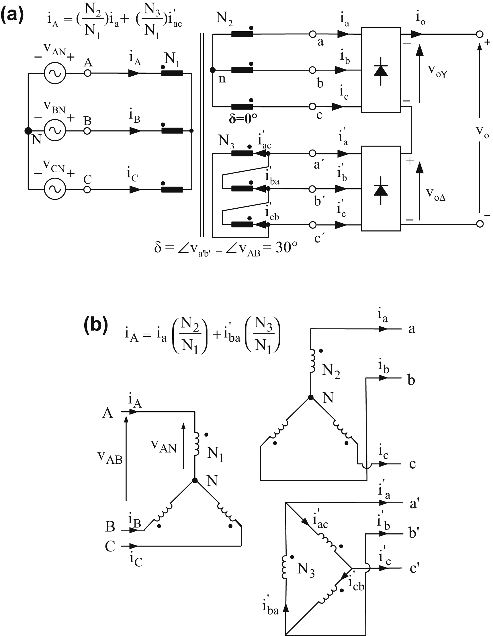
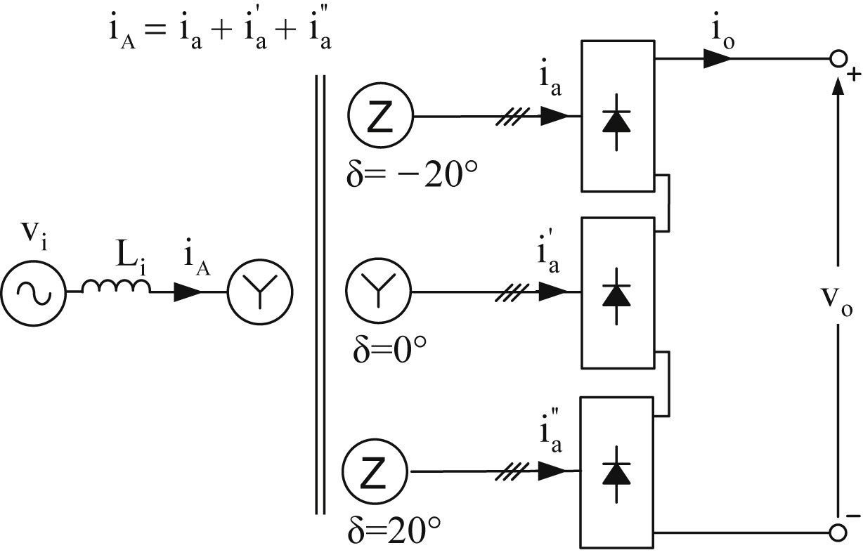
Fig. 4.14 presents the power circuit of a 12-pulse rectifier topology consisting of two 6-pulse rectifiers and a Y-Y-Δ transformer. It should be pointed out, that the voltages in the delta-connected secondary winding exhibit a phase difference of 30° with respect to the star-connected winding voltages. It should be noted that in order for the two secondary windings to have the same line-to-line voltages, the turns ratio between the two secondary windings must satisfy the equation  .
.
The 12-pulse rectifier when compared to the 6-pulse rectifier exhibits the following advantages:
• The average value of the maximum output voltage is double and, consequently, supplies the load with double power.
• The output voltage exhibits lower ripple and, consequently, a smaller output filter will be needed. This is achieved with the help of the input transformer due to the phase difference of 30° between the power supply voltages of the two six-pulse rectifiers.
• The current drawn from the input ac source has lower harmonic content which results in higher input power factor and smaller input filter. The particular transformer acts as a filter to the input current.
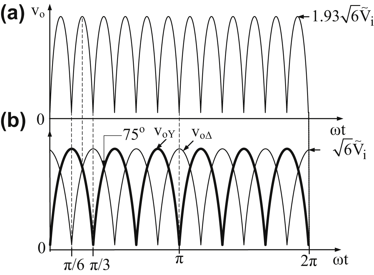
Fig. 4.15(a) shows the output voltage waveform of the 12-pulse rectifier, and Fig. 4.15(b) shows the output voltages of the two 6-pulse rectifiers which have a phase difference of 30°. The phase difference between the output voltage pulses of the two six-pulse rectifiers is created by the input transformer, which shifts the input line-to-line voltages of the lower rectifier by 30° with respect to the corresponding voltages of the upper rectifier.
The output voltage of the 12-pulse rectifier is given by the following equation:
![]() (4.115)
(4.115)
The average output voltage is given by the sum of the average voltages of the two six-pulse rectifiers as follows:
 (4.116)
where  = rms input phase voltage.
As can be seen from Fig. 4.15, the maximum value of vo is given by the sum of the values of the corresponding power supply line voltages of the two six-pulse rectifiers at their intersection point. Therefore, according to Fig. 4.15(b) the maximum output voltage is given by:
![]() (4.117)
(4.117)
Furthermore, considering Eq. (4.85) the amplitude of the output voltage of the nth harmonic component is given by:
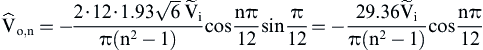 (4.118)
Fig. 4.16 presents the frequency spectrum of the output voltage of the 12-pulse diode rectifier. As can be seen from Fig. 4.16, the first output voltage higher harmonic component for the 12-pulse rectifier is the 12th while for the 6-pulse is the sixth. So the 12-pulse diode rectifier output voltage not only has a higher dc component than the 6-pulse rectifier, but also exhibits lower ripple resulting in a smaller output filter.
Fig. 4.17 shows the input current waveforms of the two six-pulse rectifiers of the 12-pulse diode rectifier for a resistive–inductive load with pure dc output current of  value (i.e., ωL ≫ R).
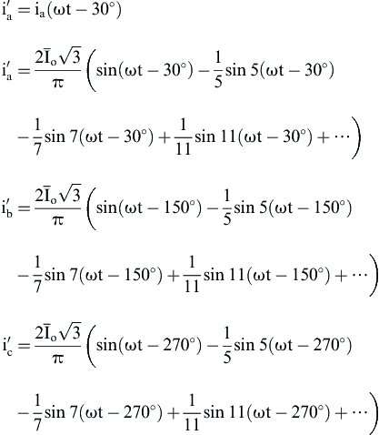
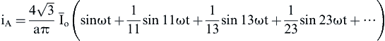
As can be seen from Fig. 4.17, the fundamental harmonic component of ia is in phase with the input phase voltage of the rectifier, and the waveforms of ia and  are of the same form but exhibit a phase difference of 30° while their pulses have a width of 120°. As has been stated in the previous section of this chapter, the harmonic components of a quasi-square-wave with a pulse width of 120° according to Eq. (4.99) are given by the following equation:
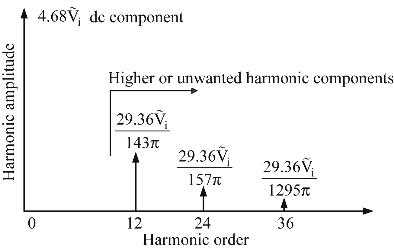
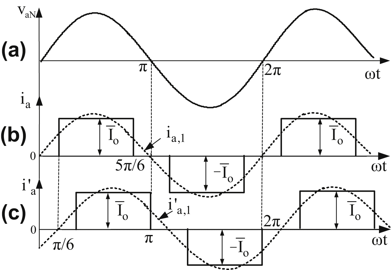
Figure 4.17 Input current waveforms of the two six-pulse diode rectifiers with a resistive–inductive load with pure dc output current of  value.
(a) Power supply input phase voltage; (b) rectifier input current from YY transformer; (c) rectifier input current from YΔ transformer.
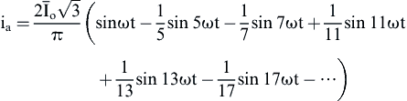 (4.119)
From Eq. (4.119) the following results are obtained:
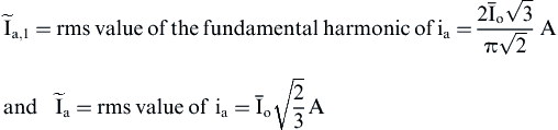 (4.120)
Moreover,
 (4.121)
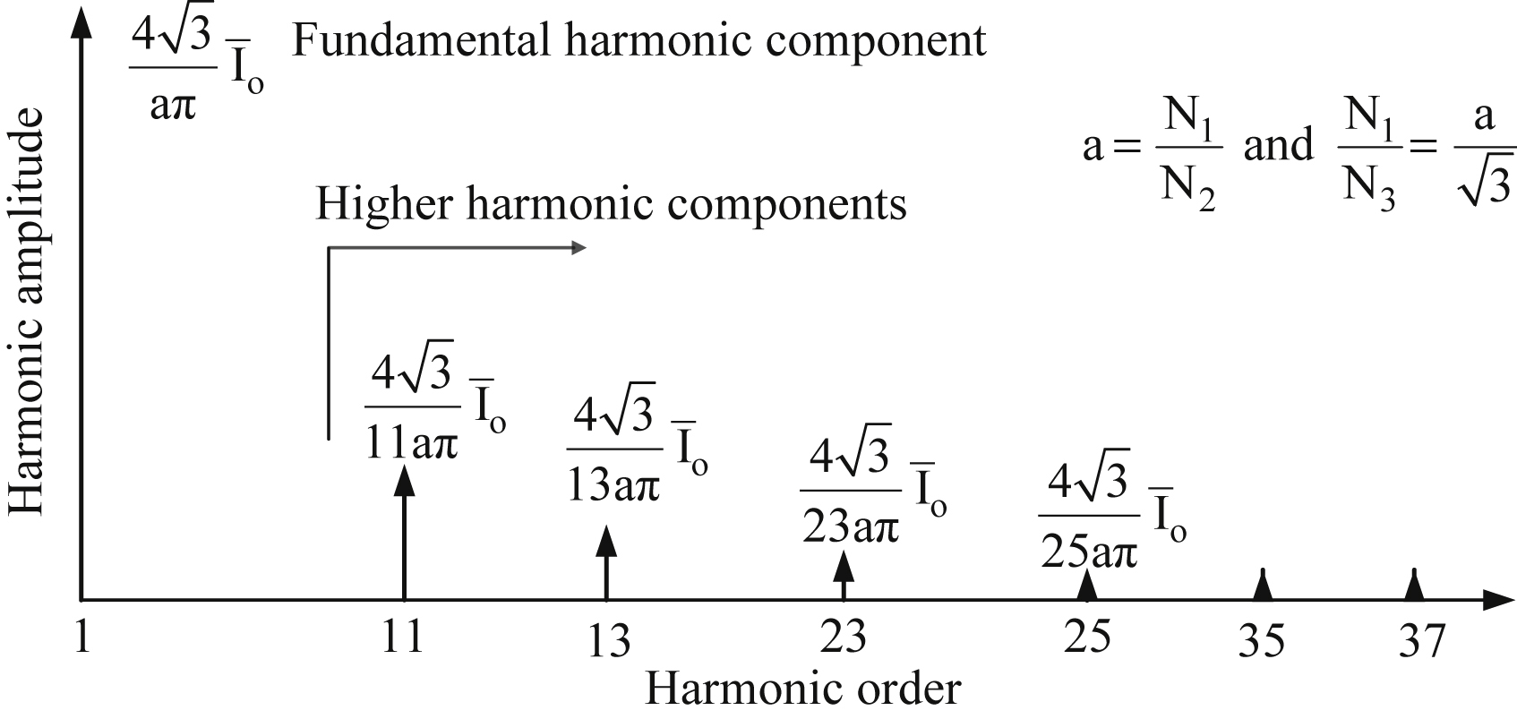
Examining Eqs. (4.119) and (4.121), it can be concluded that the input current frequency spectrum of the two six-pulse rectifiers is the same as that of Fig. 4.12.
From Fig. 4.14, it is verified that for the currents of the Δ secondary winding, the following equations hold:
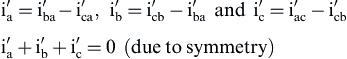 (4.122)
In Δ secondary winding a current of homopolar harmonic components ihom flows, which appears due to current asymmetries and/or due to nonlinear ferromagnetic material (i.e., core saturation phenomenon) is given by the following equation:
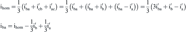 (4.123)
Using Eqs. (4.122) and (4.123), the following current equations are obtained for the Δ secondary winding of the transformer:
![]() (4.124)
(4.124)
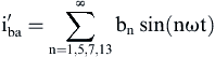
Assuming that the transformer exhibits symmetry and linear magnetization characteristics (i.e., ihom = 0), Eq. (4.124) can be written as follows:
![]() (4.125)
(4.125)
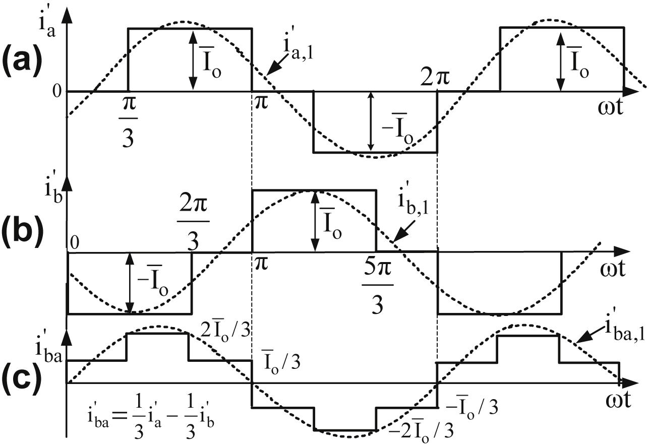
Fig. 4.18 shows the current waveforms of the transformer Δ secondary winding.
 (4.126)
where
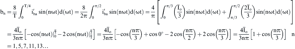 (4.127)


 (4.128)
Therefore, from Eq. (4.128), the following equation holds:
![]() (4.129)
(4.129)
Due to the symmetry and the stepwise nature of  waveform, its rms value for the interval 0 ≤ ωt ≤π/2 is equal to that of one cycle and is given by the following equation:
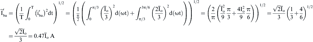 (4.130)
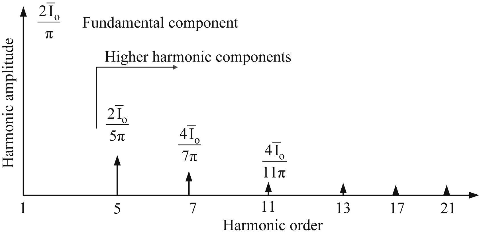
Fig. 4.19 presents the frequency spectrum of the phase current that flows through the Δ secondary winding.

Examining Fig. 4.14, it is concluded that the power supply current iA of the 12-pulse diode rectifier is given by:
![]() (4.131)
(4.131)
The transformation ratios of the YYΔ transformer are given by:
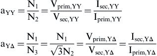 (4.132)
Selecting the number of turns ratio of the transformer in such a way that the power supply line-to-line voltages of both six-pulse rectifiers are equal will yield:
![]() (4.133)
(4.133)
and, therefore, Eq. (4.131) becomes:
![]() (4.134)
(4.134)
Using Eq. (4.134) and Fig. 4.18, the waveforms of Fig. 4.20 are obtained. As can be seen from Fig. 4.20, the fundamental components of the four currents are in phase.
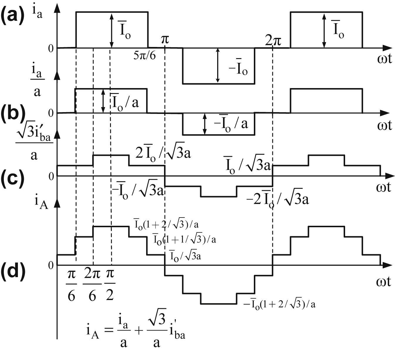
Figure 4.20 Transformer current waveforms of 12-pulse diode rectifier with resistive–inductive load and pure dc output current of  value.
(a) Current of Y secondary winding; (b) current of Y secondary winding in relation to primary; (c) current of Δ secondary winding in relation to primary; (d) power supply current.
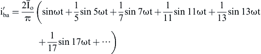
Using Fig. 4.20(d), the power supply current can be represented by the following Fourier series:
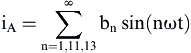 (4.135)
where
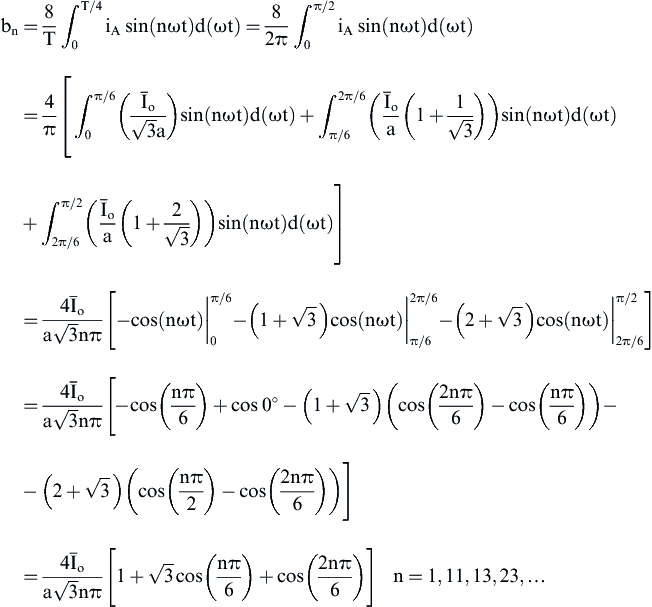 (4.136)
Therefore, using Eqs. (4.135) and (4.136) the power supply current can be represented by the following Fourier series:
 (4.137)
![]() (4.138)
(4.138)
Due to the symmetry and the multilevel form of iA waveform, its rms value for the interval 0 ≤ ωt ≤ π/2 is equal to that of one cycle and is given by the following equation:
 (4.139)
As can be seen from Eq. (4.137), the power supply current iA spectrum does not include the 5th, 7th, 17th, and 19th components as it happens with power supply current spectra of the six-pulse rectifiers. This means that the 12-pulse rectifier will need a smaller input filter to satisfy a required THD. Fig. 4.21 presents the frequency spectrum of the 12-pulse rectifier power supply current.
Using the frequency spectra of ia, , and iA, their THD% factors are calculated:
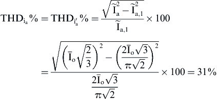 (4.140)
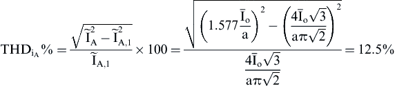 (4.141)
From the above THD factors, one can see the low harmonic content of the 12-pulse rectifier input current compared to the six-pulse.
Fig. 4.22 shows the rectifier current waveforms for a resistive–inductive load with a low-output current ripple.
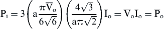
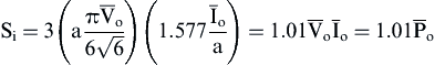
Taking into consideration the fact that for the 12-pulse diode rectifier the phase difference between the power supply voltage and the power supply current fundamental component is equal to zero (Figs. 4.17, 4.18, and 4.20), the following equations are obtained:
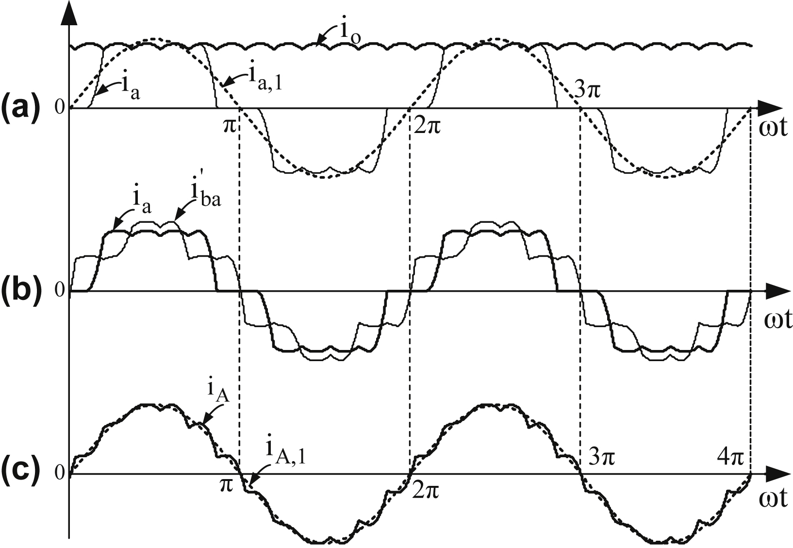
Figure 4.22 Current waveforms of 12-pulse diode rectifier with resistive–inductive load.
(a) 12-pulse rectifier output current and Y secondary winding current; (b) Y secondary current ia and Δ secondary winding phase current ; (c) power supply current iA.
 (4.142)
![]() (4.143)
(4.143)
![]() (4.144)
(4.144)
 (4.145)
![]() (4.146)
(4.146)
 (4.147)
 (4.148)
![]() (4.149)
(4.149)
![]() (4.150)
(4.150)
The number of six-pulse rectifier units required to generate a number of output pulses and the phase difference required between the input power supply voltages of the six-pulse rectifiers are given by the following equations:
![]() (4.151)
(4.151)
 (4.152(a))
Moreover, the average output voltage of a multi-pulse rectifier is given by:
![]() (4.152(b))
(4.152(b))
Fig. 4.23 shows the power circuit of an 18-pulse rectifier.
Table 4.5 presents some general useful relations for power electronics analyses.
..................Content has been hidden....................
You can't read the all page of ebook, please click here login for view all page.