
Power System Energy Storage Technologies
Abstract
Electrical energy storage can play an important role in electricity supply by storing off-peak energy for delivery in periods of peak demand and by helping to stabilize the generation from intermittent resources such as wind and solar power. Analysis suggests that for optimum grid stability, 15% of capacity should be based on energy storage. However, the storage of electricity has proved difficult to master. The main large-scale energy storage technologies are pumped storage hydropower, compressed-air energy storage, and, at the lower capacity range, batteries. For smaller-scale storage supercapacitors and flywheels can be used and small superconducting magnetic energy storage rings have been used in some grid stability applications. Pumped storage hydropower accounts for most of the capacity already in place and much of this was built to support nuclear-generating capacity. There is interest today in energy helping the integration of intermittent renewable capacity.
Energy storage plays a vital part in the modern global economy. At a national level, oil and gas are regularly stored by both utilities and governments, while at a smaller scale petrol stations store gasoline and all cars carry a storage tank to provide them with the ability to travel a significant distance between refueling stops. Domestic storage of hot water is also usual in modern homes. Yet when it comes to electrical energy, storage on anything but a small scale in batteries is rare.
Part of the reason for this is that storage of electricity, although it can be achieved in a number of ways, is difficult. In most storage technologies the electricity must be converted into some other form of energy before it can be stored. For example, in a battery it is converted into chemical energy, while in a pumped storage hydropower plant the electrical energy is turned into the potential energy contained within an elevated mass of water. Energy conversion makes the storage process complex and the conversion itself is often inefficient. These and other factors help to make an energy storage system costly.
In spite of such obstacles, large-scale energy storage plants have been built in many countries. In the majority of cases these installations are pumped storage hydropower plants, often built to capture and store power from base-load nuclear power plants during off-peak periods. Many of these storage plants were built in the 1970s. More recently there has been renewed interest in technologies such as pumped storage for grid support, particularly in European countries that are installing large capacities of renewable capacity such as wind and solar power. However, the economics of energy storage often make construction difficult to justify in a liberalized electricity market.
While economics may not always favor their construction, energy storage plants offer significant benefits for the generation, distribution, and use of electric power. At the utility level, for example, a large energy storage facility can be used to store electricity generated during off-peak periods (typically overnight), and this energy can be delivered during peak periods of demand when the marginal cost of generating additional power can be several times the off-peak cost. Energy arbitrage of this type is potentially a lucrative source of revenue for storage plant operators and is how most pumped storage plants operate.
At a smaller scale, energy storage plants can supply emergency backup in case of power plant failure, as well as other grid support features that help to maintain grid stability. They can also be employed in factories or offices to take over in case of a power failure. Indeed, in a critical facility where an instantaneous response to loss of power is needed, a storage technology may be the only way to ensure complete reliability.
Energy storage also has an important role to play in the efficient use of electricity from renewable energy. Many renewable sources of energy, such as solar, wind, and tidal energy, are intermittent and so are incapable of supplying electrical power continuously. Combining some form of energy storage with a renewable energy source helps remove this uncertainty and increases the value of the electricity generated. It also allows all the renewable energy available to be used. Today, the shedding of excess renewable power when demand does not exist for it, or when the grid cannot cope with it, is becoming common on some grid systems with high renewable capacity.
While there are many types of electrical energy storage systems, pumped storage hydropower plants account for virtually all grid storage capacity available today with perhaps 130 GW of generating capacity in operation, based on estimates by the International Hydropower Association.1 This was effectively the only large-scale energy storage technology available until the late 1970s but in the past 30–40 years new interest has been stimulated and a range of other technologies have been developed. These vary in size so that some are suitable for transmission system–level storage while others are more suited to the distribution grid or even for small micro-grids. They include a range of battery storage systems, compressed-air energy storage, large storage capacitors and flywheels, superconducting magnetic energy storage, and systems designed to generate hydrogen as an energy storage medium. The widespread adoption of electric vehicles that use battery energy storage could potentially offer a major new means of storing grid electricity too.
If deployed widely, these technologies could potentially transform the way the grid-based delivery of electrical energy operates by eliminating the need for expensive peak power plants while at the same time integrating the range of renewable generation technologies now available. This would, in turn, eliminate the vulnerability of electricity production to the vagaries of the global fossil fuel markets, creating more stable economic conditions everywhere. There is no consensus on how much storage capacity would be required to achieve this on a mature national grid but it could be equivalent to around 10–15% of the available generating capacity.
In spite of the apparent advantages offered by energy storage, widespread adoption remains slow. Cost appears to be the main obstacle, although developments are slowly bringing costs down. At the same time the growth of distributed generation is offering new opportunities for small-scale energy storage facilities. This chapter will look at the range of technologies available and where they might fit into the electricity system.
Types of energy storage
Electricity is an ephemeral form of energy that normally has to be used as soon as it has been generated. This is why the role of system operators and their electricity dispatching systems are important; they have to balance the demand for electricity with its supply. If one fails to match the other, problems occur: system voltages rise or fall and grid frequency may change and cause problems across the grid. It would seem obvious, given this situation, that some reservoir of saved electricity would be a major boon to grid operation. Yet storing electricity has proved difficult to master.
Storing electricity in its dynamic form, amps and volts, is almost impossible. The nearest one can get is a superconducting magnetic energy storage ring that will store a circulating DC current indefinitely provided it is kept cold. A capacitor storage system stores electricity in the form of static electric charge. All other types of energy storage convert the electricity into another form of energy. This means that the energy must then be converted back into electricity when it is needed.
A rechargeable battery may appear to store electricity but in fact it stores the energy in chemical form. A pumped storage hydropower plant stores potential energy, a flywheel stores kinetic energy, and a compressed-air energy storage plant stores energy in the form of compressed air, another type of potential energy. Alternatively, one might use electrolysis to turn electricity into hydrogen, yet another chemical transformation of the energy. This can then be burned in a thermal power plant or used in a fuel cell to turn it back into electricity.
The storage systems based on these processes are all viable ways of storing electricity and many of them are commercially available. Each has different characteristics, such as response time and storage efficiency, that helps differentiate the technologies and define their applications.
Some of these systems can deliver power extremely rapidly. A capacitor can provide power in 5 ms, as can a superconducting energy storage system. Flywheels are very fast too, and batteries should respond in tens of milliseconds. A compressed-air energy storage plant probably takes 2–3 minutes to provide full power. Response times of pumped storage hydropower plants can vary between 10 seconds and 15 minutes. This technology is generally suitable for peak power delivery but less suited to fast-response grid support.
The length of time the energy must be stored will also affect the technology choice. For very long-term storage of days or weeks, a mechanical storage system is best, and pumped storage hydropower is the most effective provided water loss is managed carefully. Batteries are also capable of holding their charge for extended periods. Energy loss in other systems will make them less practical for long-term storage. For daily cycling of energy, both pumped storage and compressed-air energy storage are suitable, while batteries can be used to store energy for periods of hours. Capacitors, flywheels, and superconducting magnetic energy storage are generally suited to short-term energy storage, though flywheels can be used for more extended energy storage too.
Another important consideration is the efficiency of the energy conversion process. An energy storage system utilizes two complementary processes: storing the electricity and then retrieving it. Each will involve some loss. The roundtrip efficiency is the percentage of the electricity sent for storage that actually reappears as electricity again. Typical practical figures for different types of systems are shown in Table 10.1.
Table 10.1
Roundtrip Efficiency of Energy Storage Technologies
| Energy Storage Technology | Roundtrip Storage Efficiency |
| Capacitors | 90% |
| Superconducting magnetic energy storage | 90% |
| Flow batteries | 90% |
| Compressed-air energy storage | 65% |
| Flywheels | 80% |
| Pumped storage hydropower | 75–80% |
| Batteries | 75–90% |
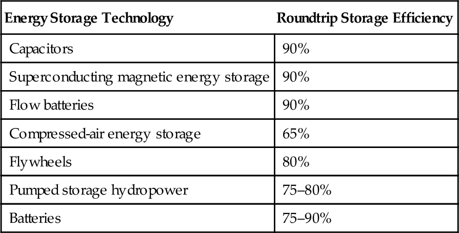
Electronic storage systems such as capacitors can be very efficient, as can batteries. However, the efficiencies of both will fall with time due to energy leakage. Flow batteries, where the chemical reactants are separated, perform better in this respect and will maintain their roundtrip efficiency better over time. Mechanical storage systems, such as flywheels, compressed-air energy storage, and pumped storage hydropower, are relatively less efficient. However, the latter two, in particular, can store their energy for long periods if necessary without significant loss.
All these factors must be taken into consideration when considering the most suitable energy storage technology for a given application. For large-scale utility energy storage there are three possible technologies to choose among: pumped storage hydropower, compressed-air energy storage, and, at the low end of the capacity range, large batteries. Batteries can also be used for small- to medium-size distributed energy storage facilities,2 along with flywheels and capacitor storage systems. Meanwhile, fast-acting, small superconducting magnetic energy storage units are being used to aid grid stability. Superconducting facilities have been considered in the past for large-scale energy storage too, but they appear to be prodigiously expensive based on the technology available today.
Pumped storage hydropower
Pumped storage hydropower is both the simplest and most widely used technique for storing electrical energy today. It was first deployed in Switzerland around 1904,3 and there is probably around 130 GW of capacity in use, though estimates vary. These plants vary in size from a few megawatts to over 1000 MW, with the largest close to 3000 MW in capacity. Plants can be found in Australia and China across Europe and in Russia, but the largest aggregate capacities are in Japan and the United States. Many are used in conjunction with nuclear power plants so that the latter can operate at full power irrespective of demand. However, some smaller plants are also used for peak shaving and load management duties independent of the availability of nuclear power.
The reservoir-based pumped storage plant is an adaptation of the conventional hydropower plant to enable it to operate reversibly (Figure 10.1). In a conventional hydropower plant with a reservoir water collects in the reservoir and is then released through the plant’s turbines as power is required. This confers an element of energy storage but the water in the reservoir can only be used once.
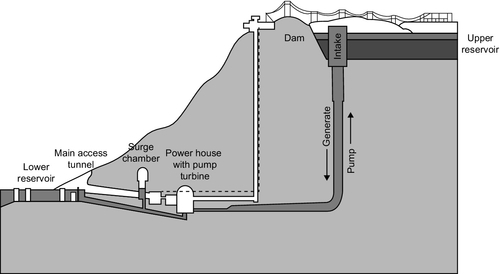
In a pumped storage plant there is a second reservoir below the turbine hall. Water that has been released from the first reservoir and used to generate electricity is collected again here and stored. The power station is also equipped with pumps—in most cases its power turbines can be operated in reverse as pumps—and during periods when excess power is available on the grid these pumps are used to pump the water that has been collected in the reservoir below the turbine hall back into the higher reservoir above the turbine hall. The water is cycled between the two reservoirs to provide either power or energy storage as needed.
This type of plant is extremely robust and though roundtrip efficiency is lower than for some other technologies, long-term energy losses are low. Leakage and evaporation are the main sources of loss and, if these are managed well, water loss can be kept small. Today this is the only technology available for very large-scale energy storage.
Pumped Storage Technology
The basic layout of a pumped storage hydropower plant involves two reservoirs, one above the other, and a turbine/pumping hall capable of both generating power from the stored water in the upper reservoir and pumping water from the lower reservoir back to the upper. For hydropower plants, in general, the energy available from a given volume of water is greater, the greater the head of water. In the case of the pumped storage plant this head is the vertical distance between the upper reservoir and the turbines. The greater this distance, the more energy a given quantity of water can store; put another way, the larger the head, the smaller the volume of water needed for a given amount of energy. However, the pumped storage head will be limited by the type of turbine that can be utilized.
While the highest head available would in theory be best, very high heads require Pelton turbines to exploit them efficiently and these cannot be used as pumps. A very high-head plant would, therefore, require separate pumps and turbines, as was used in the earliest pumped storage facilities. Using separate pumps and turbines is more expensive than using a single-pump/turbine unit. Therefore, most pumped storage plants use Francis or Deriaz turbines, which can be used in both modes. This limits the head that can be used to achieve good efficiency to about 700 m. Modern multistage pump turbines may be capable of extending this to around 1200 m.
A pump turbine may not achieve the efficiency possible when using independently optimized pumps and turbines, but the best combined pump turbines are capable of reaching around 95% efficiency for generation and 90% for pumping, leading to a roundtrip efficiency of 86%. Most plants operate in the 75–80% range.
The Francis turbine is the type most commonly used as a pump turbine. While highly efficient, it has fixed blades so the blade design is generally a compromise designed to optimize both generation and pumping efficiency. The Deriaz turbine is of similar design but with adjustable blades making it possible to optimize for generation and pumping independently. These have been used for pumped storage plants in several parts of the world but will generally be more costly than Francis turbines because of the additional complexity.
Variable-Speed Operation
While most pumped storage hydropower plants have been built using pump turbines that operate at a fixed speed that is synchronized with the grid there are significant advantages to be gained by having the ability to operate at variable speed. For pumping, variable-speed operation allows the pump to function with surplus power at different demand levels and it can take power while the demand level is changing on the grid, allowing for much greater flexibility of operation. In generation mode, variable-speed operation allows the unit to supply varying quantities of power. A fixed-speed turbine can only supply its rated output at grid frequency.
Variable-speed operation requires that the turbine generator be decoupled from the grid through a power electronic interface so that the electricity produced by the turbine at variable frequency can be injected into the grid at the synchronous frequency, or the latter can be adjusted when in pumping mode to allow variable pumping capacity. Therefore, a variable-speed pump generator will be more costly than a fixed-speed unit.
Pumped Storage Sites
The single greatest limitation (aside from economics) faced by pumped storage hydropower is the availability of suitable sites. A plant of this type requires two reservoirs at different heights. This can be difficult to engineer.
In rare cases it is possible to find two existing lakes that can be utilized to create a pumped storage facility. If natural lakes are exploited, it will be necessary to take into account the fact that the water level in both will vary more widely than it would naturally and assessing the environmental impact of these changes. More commonly, a natural lake might form one reservoir while the second is human-made. The third option is for both reservoirs to be human-made. However, this can add significantly to the capital cost of such a plant.
A further, and yet rarely attempted, solution is to use the sea as the second or lower reservoir. This is the layout of the 30 MW Yanbaru seawater pumped storage plant in Japan. One other idea that has never yet been exploited is to bury the lower reservoir underground in a suitable geological formation.
Plant capability depends on both the size of the reservoirs and the head, or vertical, height between them. The volume of the reservoirs will determine the overall capacity of the plant to store and supply energy. The more water, the more energy it can contain. However, for a given storage capacity, the output will depend both on the size of the turbines and the head. A high head can deliver more power from a given flow of water than a small head.
Performance
Pumped storage plants are capable of rapid response to sudden changes in demand. The Dinorwig plant in Wales can go from standby to synchronization at full output of 1320 MW in 12 seconds, a ramp rate of 110 MW/sec. Other, more modern pumped storage plants have been specified to be capable of output ramping when in operation at up to 500 MW/min, which compares favorably with gas turbine peaking plants and modern combined cycle power plants.
With adequate control of evaporation and leakage, the energy stored in a pumped storage reservoir can be retained indefinitely. This is not a significant advantage when most plants cycle daily, but it could prove so under circumstances where energy needs to be stored seasonally, such as solar power for use in winter, or wind power for use in less windy summer months.
Costs
An energy storage plant such as a pumped storage hydropower plant will depend for its revenue on being able to buy power at low cost and then sell it at higher cost. The income will, therefore, vary depending on a wide range of conditions. From an economic point of view the capital cost of building the plant will be the most important factor in determining its viability. This is likely to be relatively high because, like most hydropower plants, pumped storage is a capital-intensive technology.
At the top end, capital costs are likely to be as high or higher than for a traditional hydropower plant, which, as shown in Chapter 8, are generally in the range $1000–2000/kW. A 500 MW plant proposed for construction in California has an estimated cost of $1.1 billion and a capacity of 500 MW, or around $2200/kW. In contrast, the Tianghuangping pumped storage plant in Zhejiang province, China, cost $1.1 billion for 1800 MW when it came on-line in 2001, around $600/kW. Much of the difference can probably be accounted for by the lower labor costs in China.
Small pumped storage plants are likely to be relatively more expensive than larger installations.
Compressed-air energy storage
Compressed-air energy storage (CAES) is a system whereby energy is stored in the form of air pressurized above atmospheric pressure. Compressed air has a long history as a means of both storing and distributing energy. Systems based on this energy distribution medium were installed during the late 19th century in cities as various as Paris (France), Birmingham (U.K.), Dresden (Germany), and Buenos Aries (Argentina) to supply power for industrial motors and commercial use in a variety of applications including the textile and printing industries.
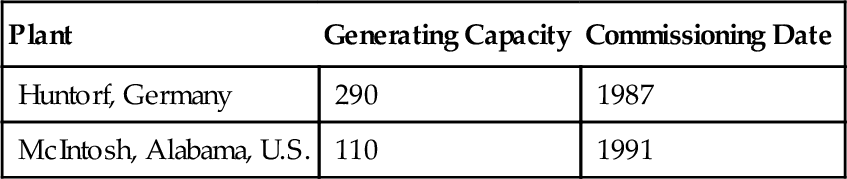
The use of compressed-air storage as an adjunct to the power grid began with the construction of the Huntorf power plant that was built in Germany in 1978 but only operated commercially for 10 years. A second CAES plant was built by the Alabama Electric Cooperative in the United States and entered service in 1991. The latter facility has continued to provide storage services ever since. Details of these two plants are shown in Table 10.2.
Table 10.2
Commercial CAES Plants
| Plant | Generating Capacity | Commissioning Date |
| Huntorf, Germany | 290 | 1987 |
| McIntosh, Alabama, U.S. | 110 | 1991 |
In spite of being championed by organizations such as the U.S. Electric Power Research Institute, no further commercial project has ever been built, although others have been proposed and work even started on two. Even so, CAES remains of interest because it is the only other very large-scale energy storage system after pumped storage hydropower. Individual CAES plants are generally smaller than typical pumped storage plants but sites suitable for their construction are much more widespread than those for the hydropower storage plants. They could, therefore, provide a more widely distributed large-scale energy storage network.
Compressed-Air Energy Storage Principle
A CAES plant requires two principal components: a storage vessel in which compressed air can be stored without loss of pressure, and a compressor/expander to charge the storage vessel and then extract the energy again (Figure 10.1). (The latter might, in fact, be a compressor and a separate expander.) In operation the plant is broadly analogous to the pumped storage hydropower plant. Surplus electricity is used to compress air with the compressor and the higher-pressure air is stored within the storage chamber. This stored energy can then be retrieved by allowing it to escape through the expander, an air turbine that is essentially a compressor operating in reverse. The expanding air drives the air turbine, which turns a generator to provide electrical power.
The compression and expansion functions of the CAES plant can be performed by the two primary components of a standard gas turbine. As seen in Chapter 4, the gas turbine comprises three components: a compressor, combustion chamber, and turbine. If the combustion chamber is removed and the two rotary components separated, then these can alternately use electricity to compress air for storage and extract energy from it again to regenerate the stored power (Figure 10.2).
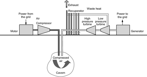
In practice, a slightly different arrangement is preferred that is closer still to the gas turbine. A rotary gas turbine compressor is used to compress air that is then stored in the storage chamber. When power is required, compressed air is extracted again and fed into a combustion chamber where it is mixed with fuel and ignited, generating a higher-pressure, higher-temperature thermodynamic fluid that is then used to drive the turbine stage of the plant.
Since a plant operated in this way requires natural gas or another fuel, it is not a straightforward energy storage system. However, the economics of this mode of operation appear to be the most attractive because it can generate more electricity than was used to store the compressed air. Additional generation is between 25% and 60% depending on the plant design. A further advantage is that the turbine stage of the plant does not have to drive the compressor as it would in a conventional gas turbine, so it can generate up to three times more power than it would when coupled to a compressor. Therefore, turbines for CAES plants are relatively smaller than for a similar generating capacity gas turbine.
Compressed-Air Storage Facilities
The most important part of a CAES plant is somewhere to store the compressed air. Small-scale CAES plants—with storage capacities up to 100 MWh and outputs up to 20 MW—can use aboveground storage tanks built with steel pressure vessels but large, utility-scale plants need underground caverns in which to store the air. The natural gas industry has used underground storage caverns for years to store gas; these same caverns can provide ideal storage facilities for a CAES plant. However, the demand for such a cavern limits the development of CAES to places where such storage caverns are available.
A number of different types of underground caverns can be exploited. The most expensive is a human-made rock cavern excavated in hard rock or created by expanding existing underground mine workings. Such a site must be located in an impervious rock formation if it is to retain the compressed air without loss so the suitability of underground coal mines and limestone mines will depend on whether they are air-tight.
Salt caverns are another type of storage site, one that has been commonly used for gas storage. These are created within naturally occurring underground salt domes by drilling into the dome and pumping in water to dissolve and remove the salt to create an enclosure. Salt deposits suitable for such caverns occur in many parts of the world.
It is another type of geological structure, however, an underground porous rock formation, which offers the cheapest underground storage facility. Structures of this type suitable for gas storage are found where a layer of porous rock is covered by an impervious rock barrier. Examples can be found in water-bearing aquifers, or in porous underground strata from which oil or gas have been extracted. Aquifers can be particularly attractive as storage media because the compressed air will displace water within the porous rock, setting up a constant-pressure storage system. With rock and salt caverns, in contrast, the pressure of the air will vary as more is added or released.
All three types of underground storage structures require sound rock formations to prevent the air from escaping. They also need to be sufficiently deep and strong to withstand the pressures imposed on them. It is important, particularly in porous-rock storage systems, that there are no minerals present that can deplete the oxygen in the air by reacting with it. Otherwise, the ability of the air to react with the fuel during combustion will be affected, reducing the power available during the generation phase of the storage generation cycle.
Underground rock structures capable of storing compressed air are often widely available. For example, a survey in the United States found accessible sites of different types across 80% of the country.
Turbine Technology and CAES Cycles
A CAES plant generally exploits standard gas turbine compressor and turbine technology, but because the two units operate independently, they can be sized differently to match the requirements of the plant. The larger the compressor compared to the turbine, the less time it requires to charge the cavern with a given amount of energy. The Hundorf plant that was built in Germany required 4 hours of compression to provide 1 hour of power generation, whereas the McIntosh plant in Alabama needs only 1.7 hours of compression for 1 hour of generation.
As a consequence of compression and generation being separated, a CAES plant turbine can operate well at part load as well as full load. More complex operation is also possible. The Alabama plant, for example, uses two turbine stages with the exhaust from the last turbine is used to heat air from the cavern before it enters the first turbine. Fuel is not actually burned in the compressed air until it enters a combustion chamber between the first and second chambers.
Many of the refinements used to improve gas turbine performance outlined in Chapter 4 can be used in CAES plants too. For example, the compressor can be divided into two sections with air cooling between the stages to reduce its volume (intercooling) and heat from the turbine exhaust can be recovered and used to heat the compressed air extracted from the storage chamber (recuperation). Reheating, where the turbine is divided into two stages with an additional combustion chamber between stage one and stage two can also be applied versions of these latter two are used in the McIntosh plant, as noted before.
Mechanical components are never 100% efficient so there are consequential energy losses during compression and expansion in a CAES plant. There is also an additional source of energy loss. When air is compressed it generates heat and this heat energy is lost in a conventional CAES plant. A proposed additional refinement to the conventional mode of operation involves capturing this heat and storing it for use to heat the pressured air as it exits the storage chamber, before entering the turbine. This adiabatic cycle could theoretically be used to design a CAES plant that has no need for additional fossil fuel and that could achieve a roundtrip efficiency of 65%.
In principle a CAES plant could be of virtually any size and one proposed project would have had a generating capacity of 2400 MW. However in practice most schemes are likely to be smaller than this, in the tens or hundreds of megawatts range. Startup for the two plants that have operated was around 12 min but both could be brought into service in 5 min if necessary. Round trip efficiency without the use of additional fuel will be low for conventional CAES plants such as the two that have operated but, as noted, refinements could improve this.
Costs
There is little experience with CAES so any cost estimates must be considered tentative. However, it would appear to be an economically attractive option for energy storage. Proposals within the last 10 years or so for conventional CAES plants in the United States have had installed costs of $400–900/kW depending on size and storage type. An adiabatic plant is likely to be much more expensive, with potential costs as high as $1700/kW.
Large-scale batteries
Batteries are the most widely known means of storing electrical energy. Invented during the 19th century, they are now used for a whole range of portable applications from starter motor power in vehicles to providing an electrical source for mobile phones, tablet computers, and tiny electronic devices such as hearing aids. More recently, batteries have also been used in a range of mostly small renewable energy applications, and in addition some large cells have been used for grid storage and stability uses.
All batteries are electrochemical devices that convert the energy that is released during a variety of chemical reactions into electrical energy. This energy would normally be released as heat if the reaction was permitted to proceed conventionally by mixing the reactants. In an electrochemical cell (i.e., a battery) the reaction is controlled in such a way that most of this heat can be converted into electricity.
There are two distinct battery types in common use: primary cell and secondary cell. A primary cell (or battery) can only be used once. After that it cannot be recharged. However, a secondary cell is capable of being recharged, reversing the internal chemical reaction and regenerating the reactants that provided the power in the first place. It is these secondary cells that are of use in the power and utility industries.
Secondary cells can be further divided into two types: standard secondary cells and flow batteries. Standard cells are the type found in portable computers or vehicles. They are completely self-contained, and have no mechanical parts. Charging and discharging is carried out via the cell terminals and all of the reactants required are contained within the battery package. Secondary cells can be found in two types: shallow discharge cells, such as those used for vehicle starter power, which are never fully discharged, and deep discharge cells that can be completely exhausted without damage.
A flow battery is different because the actual cell within which the chemical reactants react and generate electricity does not carry the reactants themselves. Instead, these are stored in external reservoirs and pumped through the cell as required. This type of battery is more complex than a conventional secondary cell, but it has the advantage that battery capacity is limited by reservoir size and this can easily be increased for relatively little cost. On the other hand, flow batteries tend only to be economical in large sizes because of the additional cost associated with their construction.
Battery Principle
A battery is a device that can exploit a chemical reaction to produce electricity. The reactions upon which a cell is based will define the particular cell type. In all cases the reaction will occur spontaneously if the reactants are mixed, generating heat in the process. However, in the battery the reactants are separated and only allowed to react in a particular way.
The chemical reaction used in every battery can notionally be divided into two half-reactions and the battery will contain two electrodes, called the anode and cathode; each electrode is associated with one of these half-reactions. The half-reactions involve the creation of charged ions and the capture or release of electrons. Under normal circumstances where the reactants are intimately mixed, these processes occur simultaneously at the same location. However, in a battery the two electrodes are separated by an electrolyte that will allow charged ions to pass from one electrode to the other but will not allow electrons to pass. These can only cross from one electrode to the second to complete the reaction through an external circuit. This is the electrical current that can be used to drive electrical and electronic equipment. It is this separation of processes by the use of a selective filter (in this case, the electrolyte) that allows the cell to generate power.
As mentioned, batteries are generally divided into primary cells and secondary cells. Primary cells contain reactants that will only react once to produce power. After that the cell is spent. A secondary cell can be recharged by applying a reverse polarity to the cell, reversing the chemical cell reaction and regenerating the original cell reactants. It is this type of cell that is of use for energy storage.
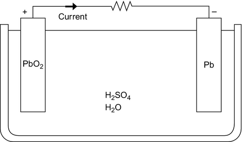
There are a number of battery types that can be used for grid and utility applications. The most widely used secondary cell is the lead-acid battery, similar to the type commonly used in vehicles (Figure 10.3). Lead-acid batteries account for roughly half of all secondary cell sales, globally, and are widely available. Another type, nickel-cadmium (NiCad) batteries, are less common. NiCad batteries were used for portable computers until they were superseded by alternatives that were better suited to the duty cycle of such devices. They have also been used for automotive applications, particularly under low-temperature conditions when they behave more reliably than lead-acid cells. Other cell types developed specifically for portable electronic devices include nickel-metal hydride cells and lithium-ion cells. Both are potentially useful for utility storage. A high-temperature battery, the sodium-sulfur battery, has also been popular for utility applications.
In addition to these conventional secondary cells, a variety of devices known as flow cells or flow batteries have also been tested for large-scale energy storage applications. These include zinc-bromide, vanadium-redox, and polysufide-bromide flow cells. None has so far found widespread commercial application but new types are being developed. They are considered attractive because they have much longer lifetimes than conventional secondary batteries.
Traditional electrochemical storage systems boast a best-case cycle conversion efficiency (electricity to cell storage and back into electricity) of 90%, but a more typical figure would be 70%. Most batteries also suffer from leakage of power over time. Left for too long, the cell discharges itself. This means that battery systems can only be used for relatively short-term storage. Flow cells do not suffer from this problem because the reactants are not stored together and this helps reduce long-term energy losses.
An additional problem with traditional secondary batteries is their tendency to age. After a certain number of cycles, the cell stops holding its charge effectively, or the amount of charge it can hold declines. Much development work has been aimed at extending the lifetime of electrochemical cells but this remains a problem. Again flow cells, because of their design, can avoid this problem.
Against this, batteries are able to supply their output extremely quickly—under 5 msec for a conventional battery and less than 100 msec for a flow battery. Some are also capable of very high-power outputs and discharge rates.
Lead-Acid Batteries
Lead-acid batteries were among the first secondary cells to be developed and were used for load leveling in very early power distribution systems. The cell is based on a reaction between lead-oxide and sulfuric acid. Efficiencies of lead-acid batteries vary depending on factors such as the temperature and duty cycle but are typically between 75% and 85% for DC–DC cycling. However, cells discharge themselves over time so they cannot be used for very long-term power storage. If cycled carefully, cells for utility applications can have lifetimes of 15–30 years.
The cells have a water-based liquid electrolyte and operate at ambient temperature. Both high and low temperatures can reduce their performance. They are also relatively heavy and have a poor energy density, although neither of these factors are a handicap for stationary applications. In addition, they are cheap and easily recycled.
Several very large energy storage facilities based on lead-acid batteries have been built. These include and 8.5 MW unit constructed in West Berlin in 1986 while the city was still divided into East and West, and a 20 MW unit built in Puerto Rico in 1994. While the former operated successfully for several years, cell degradation led to the latter closing after only five years. Lead-acid cells have been very popular for renewable applications such as small wind or solar installations where they are used to store intermittently generated power to make it continuously available.
Nickel-Cadmium Batteries
The nickel-cadmium battery is one of a family of nickel batteries that includes nickel–metal hydride, nickel-iron, and nickel-zinc batteries. There is also a nickel-hydrogen battery in which one cell reactant is gaseous hydrogen. All have a nickel electrode coated with a reactive and spongy nickel hydroxide while the cell electrolyte is almost always potassium hydroxide. Cell reactions vary depending on the second component.
The only nickel-based cell that has been exploited for utility applications is the nickel-cadmium cell. Nickel-cadmium batteries have higher energy densities and are lighter than lead-acid batteries. They also operate better at low temperatures. However, they tend to be more expensive. This type of battery was used widely in portable computers and phones but has now been superseded by lithium-ion batteries.
Efficiencies of nickel-cadmium cells are typically around 70% although some have claimed up to 85%. Lifetimes tend to be rated at around 10–15 years though some have lasted longer. These cells discharge themselves more rapidly than lead-acid cells and can lose 5% of their charge in a month. There can also be a problem with disposal since cadmium is highly toxic.
The largest nickel-cadmium battery ever built is a 40 MW unit in Alaska that was completed in 2003. It occupies a building the size of a football field and comprises 13,760 individual cells.
Lithium Batteries
Lithium batteries, including both lithium-hydride and lithium-ion batteries, have become popular for consumer electronic devices because of their low weight, high energy density, and relatively long lifetimes. Lithium is extremely reactive and can burst into flames if exposed to water, but modern lithium cells use lithium bound chemically so that it cannot react easily. As with nickel, there are a number of lithium cell variants but the most popular today is the lithium-ion cell. These are designed so that there is no free lithium present at any stage during the charging or discharging cycle.
The use of lithium batteries in grid and utility applications is beginning to grow with units being tested in a number of locations. One large installation, due to start operating in 2013, is a 2 MW lithium-ion facility for the Orkney Islands off the northwestern coast of Scotland. The future development of lithium batteries may benefit from interest by automotive manufacturers in their use in hybrid and electric vehicles.
Sodium-Sulfur Batteries
The sodium-sulfur battery is a high-temperature battery (Figure 10.4). It operates at 300 °C and utilizes a solid electrolyte, making it unique among the common secondary cells. One electrode is molten sodium and the other molten sulfur, and it is the reaction between these two that is the basis for the cell reaction. Although the reactants, and particularly sodium, can behave explosively, modern cells are generally reliable. However, a fire was reported in 2012 at a sodium-sulfur battery installation in Japan.
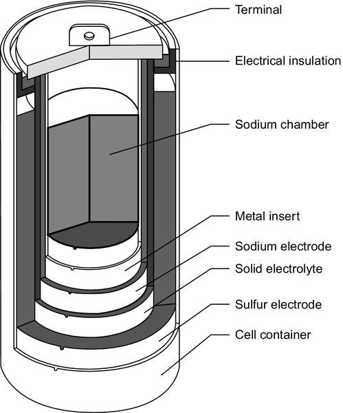
Early work on the sodium-sulfur battery took place at the Ford Motor Co. in the 1960s but modern sodium-sulfur technology was developed in Japan by the Tokyo Electric Power Co., in collaboration with NGK insulators, and it is these two companies that have commercialized the technology. Typical units have a rated power output of 50 kW and 400 kWh. Lifetime is claimed to be 15 years or 4500 cycles and the efficiency is around 85%. Sodium-sulfur batteries have one of the fastest response times, with a startup speed of 1 msec.
Flow Batteries
A flowing-electrolyte battery, or flow battery, is a cross between a conventional battery and a fuel cell. It has electrodes like a conventional battery, where the electrochemical reaction responsible for electricity generation or storage takes place, and an electrolyte. However, the chemical reactants responsible for the electrochemical reaction and the product of that reaction are stored in tanks separate from the cell and pumped to and from the electrodes as required, much like a fuel cell (Figure 10.5). The processes occurring here are usually somewhat different to the simple electrochemical process described earlier but the principle is similar.
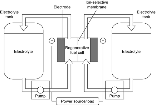
A number of flow batteries have been tested including the zinc-bromide flow battery, the polysulfide-bromide battery, and the vanadium redox battery. A number of newer designs are also in the research stage. Response times for flow batteries are longer than for conventional secondary batteries but they should be able to supply full power within 100 msec. However, flow batteries have not been extensively tested commercially so their overall performance has yet to be established.
Costs
The costs of battery systems vary widely depending on type and size. Large batteries are generally cheaper than similar small installations. Battery costs are normally based on the cost per kilowatt-hour rather than the cost per kilowatt. The cheapest of the conventional cells is the sodium-sulfur battery with a cost in the range of $250–900/kWh. Lead-acid battery costs are in the range of $400–2300/kWh and nickel-cadmium of $1800–2400/kW. Flow batteries are potentially cheaper with costs in the range of $150–800/kWh depending on the type.
Superconducting magnetic energy storage
Superconductivity offers, in principle, the ideal way of storing electric power. The storage system comprises a coil of superconducting material that is kept extremely cold. Off-peak electricity is converted to DC and fed into the storage ring where it stays, ready to be retrieved as required. Provided the system is kept below a certain temperature, electricity stored in the ring will remain there indefinitely without loss (Figure 10.6).

The key to the superconducting magnetic energy storage (SMES) device is a class of materials called superconductors. Superconductors undergo a fundamental change in their physical properties below a certain temperature called the transition temperature, which is a characteristic of each material. When a material is cooled below its transition temperature it becomes superconducting. In this state it has zero electrical resistance. This means that it will conduct a current with zero energy loss.
Unfortunately, the best superconducting materials are metallic alloys that only undergo this transition below 20 °K (− 253 °C). Temperatures this low must be maintained by cooling the superconducting coil with liquid hydrogen or liquid helium—in either case an expensive process. In recent years scientists have discovered a new range of ceramic materials that become superconducting at relatively high temperatures, temperatures accessible by cooling with liquid nitrogen. (Liquid nitrogen boils at 98 °K, − 175 °C.) Most of these materials have proved to be rather brittle ceramics that are difficult to work with but techniques are being found to exploit them. This is helping make superconductivity more economically attractive for a range of utility applications including storage.
Superconductors store DC current without loss but energy losses occur during the conversion of grid AC to DC and then from DC back to AC. The roundtrip efficiency is typically 90% for daily cycling but will be lower for long-term storage because of the energy required to maintain the coil below its transition temperature. There are also small continuous losses within the coil at the point where power is fed in and out. Startup time for a SMES system is around 5 msec.
When SMES devices were first proposed, they were conceived as massive energy storage rings of up to 1000 MW, similar in capacity to pumped storage hydropower plants. No such storage ring has ever been built, but smaller SMES devices are being used for grid support roles and this appears to be the main commercial market.
Modern technology has enabled smaller commercial SMES storage units with capacities between 100 kW and 100 MW to be constructed. The largest built to date can deliver 10 MW. The storage capacity of these commercial devices is between 10 kWh and 30 kWh, relatively low for utility storage but useful for very fast grid support functions.
One of the earliest SMES devices to be used commercially was commissioned by the U.S. Bonneville Power Administration in the 1980s. This unit had a storage capacity of 30 MJ and a power rating of 10 MW. The device could release 10 MJ of energy in one-third of a second to damp power swings on the Pacific Intertie. Today a typical commercial unit has a storage capacity of 3 MJ (0.83 kWh) and can deliver 3 MW of power for one second.
Costs
Although a few commercial SMES devices are available, costs have been difficult to establish. In general, the cost is relatively low per unit size (MW) but high in terms of storage capacity (MWh). For short-term grid stability duty, they appear to be competitive with other types of storage such as batteries, flywheels, and capacitors.
Flywheels
A flywheel is a simple mechanical energy storage device comprising a large wheel on an axle fitted with frictionless bearings. The flywheel stores kinetic energy as a result of its rotation. The faster it rotates, the more energy it stores. Provided there is a means to extract this energy again, the system can be used for a variety of energy storage applications.
Traditional flywheel-based systems have been in use as mechanical energy storage devices for thousands of years. Millstones, potters wheels, and hand looms have all used them to both store energy and smooth out the peaks in energy delivery by hand or foot. Simple flywheel energy storage devices are also fitted to all piston engines to maintain smooth engine motion. The engine flywheel is attached physically to the engine camshaft, and as the pistons cause the camshaft to rotate they feed energy into the flywheel. For electricity storage applications, energy will normally be fed into the flywheel using a reversible motor-generator.
Flywheel Principle
A flywheel depends on a rotating mass to store energy that is then held in the kinetic energy of rotation of the rotor. The stored energy is proportional to the moment of inertia of the rotor about its axis (directly related to its mass) and its rotational speed.
Conventional flywheels such as those used for piston engines are fabricated from heavy metal disks made of iron or steel. However, these disks are only capable of rotating at low speeds. For power applications, new lighter composite materials have been developed, capable of rotating at 10,000–100,000 rpm without fracturing under the immense centrifugal force they experience. These are made from carbon fiber or glass fiber composite materials that, while less dense than the metals they replace, can store more energy at the very high rotational speeds at which they operate. See Figure 10.7.
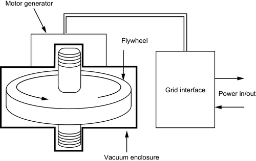
Friction losses can be significant at high rotational speeds and energy storage flywheels generally use magnetic bearings to minimize such losses. These are normally supplemented by conventional bearings in case the magnetic bearing fails. Friction losses from air drag can also be significant at the speeds at which modern flywheels rotate, so they will normally be housed in a vacuum chamber, evacuated to reduce this source of loss too. The whole device must be enclosed within an exceedingly strong container that will prevent the pieces of the flywheel scattering like shrapnel in the event of a catastrophic failure.
Energy is fed into a flywheel using a motor to rotate it up to its maximum speed. Energy is extracted from the rotor through a generator driven by the flywheel shaft. Extracting energy from the flywheel will lead to its rotational speed lowering. The makes grid synchronization virtually impossible so most flywheels use electronic AC–DC–AC converters to eliminate this problem and permit variable-speed operation. Flywheels are generally maintenance free.
Flywheel Performance Characteristics
For a flywheel to operate effectively as an electrical energy storage system it must be kept rotating at its full operating speed. This requires continuous energy feed to compensate for friction losses. Roundtrip efficiency estimates vary with some manufacturers claiming up to 90%. Other sources such as the U.S. Department of Energy suggest 70–80% is more typical.
The energy stored in a flywheel is a function of the mass of its rotor. The larger the rotor, the more it can hold. However, the power it can deliver will depend on the size of the generator used for energy extraction. Most flywheels are designed for backup power or grid support functions during which they are expected to deliver high power for a short period of perhaps a few seconds at most. Such units can have small rotors but relatively large power extraction systems. Other flywheels have been designed for long-term energy delivery. These will have rotors that are capable of storing a large amount of energy compared to the size of the energy extraction system.
Flywheels can usually respond extremely quickly. In grid backup systems they should be capable of reaching full power within half a cycle, 25 msec, and some are quoted with response times of 5 msec. Such units will probably be able to supply their full output between 5 seconds and 15 seconds.
Commercial flywheels are available with power ratings between 2 kW and 2 MW and with storage capacities between 1 kWh and 100 kWh. One of the largest commercial systems is a unit with ten 100 kW flywheels used by the New York Transit System to support its electric traction power network. This system can supply 1 MW of power for 6 seconds. However, the largest flywheel so far constructed is one used in Japan for fusion research. This system can supply 340 MW for 30 seconds.
Costs
The commercial cost of a flywheel system is around $2000/kW, although costs have been put as low as $500/kW. The cost per unit of stored energy is around $1 million/kWh for small commercial flywheel systems though it may be lower for large flywheels. These costs reflect the fact that most flywheel systems store a small amount of energy but can deliver it in a quick burst of high power.
Capacitors
Capacitors are electrical or electronic devices that store energy in the form of electrostatic charge. The simplest capacitor comprises two metal plates separated by a small air gap so that no current can pass between them. When a voltage is applied across it the plates become statically charged and this charge can later be released by creating a short circuit between the plates.
Capacitors of various sorts are key components of electrical and electronic circuitry, particularly when creating tuned circuits. While blocking DC current they will allow an AC current to pass with an amplitude that is inversely proportional to the frequency. However, conventional capacitors are capable of storing only a limited quantity of electrical energy. Since the end of the 1970s a new type of capacitor has been available, called an electrochemical capacitor, and these can store much larger quantities of energy. These capacitors, which have names like supercapacitors or ultra-capacitors, are based on electrochemical processes that are similar to those in batteries.
Energy Storage Capacitor Principles
A simple electrostatic capacitor comprises two plates with an air gap between them. When a voltage is applied to the plates, charge builds up on them to neutralize the voltage by creating an equal and opposite static-charge voltage across the plates. The charge will continue to build as the voltage is increased until it is high enough to cause air to breakdown and start conducting electricity.
The amount of charge the capacitor will hold can be increased by placing a dielectric material between the plates that reduces the strength of the field between the plates, allowing more charge to build up before breakdown occurs. An electrochemical capacitor is similar to this in that it has a dielectric material between the capacitor plates, but in this case the dielectric is a liquid electrolyte such as sulfuric acid or potassium hydroxide (Figure 10.8). The capacitor plates themselves are inert materials that will not react with these reagents.
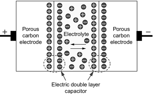
When a charge is applied to the capacitor it causes the usual charge buildup. However, in this case the charge on each plate is neutralized by an opposing layer of charged ions from the electrolyte. This creates a double layer of charge at each plate, effectively leading to two capacitive charged layers, which massively increases the amount of charge the unit can hold.
The simplest electrochemical capacitors use a water-based electrolyte, which restricts the voltage that each can support to around 0.9 V before electrolysis of the water begins. This limits the amount of charge the capacitor can hold but otherwise these capacitors have excellent characteristics. Basic capacitors of this type (known as symmetrical capacitors) have two identical electrodes made from carbon. By varying the construction of one electrode, it is possible to increase the amount of energy the device can hold. Devices of this type are called asymmetrical capacitors. A second type of electrochemical capacitor uses an organic electrolyte, which allows it to support a voltage up to 2.7 V. Both symmetrical and asymmetrical versions of these capacitors are available too. Since single capacitors of either type can only support a relatively low voltage (in grid terms), electrochemical capacitors are usually stacked in series to allow higher voltages to be exploited.
Performance Characteristics
Electrochemical capacitors can be cycled for tens of thousands of times without degradation provided the voltage across them is kept below the maximum so that no internal reaction takes place. However, once they are charged they do lose charge slowly through leakage in the same way as a battery. The leakage levels in water-based electrochemical cells are similar to those of a lead-acid battery. Leakage levels are lower with organic-based electrolytes.
Leakage will reduce long-term storage life, but with fast cycling, roundtrip efficiency can be 95% or higher. In addition, capacitors can normally discharge their energy very rapidly without damage so long as excessive internal heating is avoided. Energy density is moderate between 1 Wh/kg and 5 Wh/kg for symmetrical capacitors and up to 20 Wh/kg for asymmetrical capacitors. In comparison, a lead-acid battery has an energy density up to 42 Wh/kg. Response time is fast at 5 msec.
Units can be designed with the capability to deliver power levels between 1 kW and 5 MW, but actual energy storage capacity is generally relatively low at 1–10 kWh. When power is withdrawn from a capacitor the voltage falls, so sophisticated DC–AC conversion systems are needed to maintain a constant voltage output.
Applications
Electrochemical capacitors have been used both for energy storage and for braking energy recovery systems in automotive applications. For grid use they are best suited to backup or fast reaction grid support, offering a similar performance to flywheels. Although capacitors are not yet widely deployed for grid support they have been tested in a number of configurations. These include adding rapid-response storage to small distributed generation grids or micro-grids where they can provide fast-reacting grid support when the output from intermittent renewable resources suddenly falls and before a backup engine–based system can take over. Capacitors are also being tested for high-voltage grid support services.
Costs
The cost of capacitor storage is likely to be similar to that for flywheels at around $2000/kW. Based on cost per unit of energy storage, the price is again expected to be similar to that of flywheels with costs from $7000/kWh to perhaps $1million/kWh depending on the size of the unit. As with flywheels, this reflects the use of this in low storage capacity, high power output configurations for rapid, short-duration delivery of power.
Hydrogen energy storage
Hydrogen offers a potential energy storage medium because of its versatility. The gas can be produced by electrolysis of water, making it easy to integrate with electricity generation. Once made, the hydrogen can be burned in thermal power plants to generate electricity again or it can be used as the energy source for fuel cells. In both cases the only combustion product is water. Potentially, it may also be used as an automotive replacement for petroleum or natural gas. Finally, hydrogen has a high-energy density making it an efficient means of storing energy.
For all these reasons hydrogen has been seen as a potential fossil fuel replacement in a future energy economy. For this to become feasible, several problems must be overcome including improving efficiency of its production and finding an economical means of storing it for automotive applications. In the meantime, the limited use of hydrogen as an energy storage medium for intermittent renewable sources such as wind energy is being explored.
Hydrogen Energy Essentials
Hydrogen, as a fuel, can be generated by the electrolysis of water using an electrical voltage. This has been carried out industrially for many years with the main system being an alkaline electrolyzer, exploited most successfully by the Norwegian utility Norsk Hydro. Large-scale electrolyzers have been built that are capable of handling inputs of 100 MW for hydrogen generation and the product is around 99.8% pure. Conversion efficiency is 90%. Alternatives to the alkaline electrolyzer are proton exchange membrane electrolyzers that are currently being developed and could potentially achieve 94% efficiency, but with the need for a platinum catalyst. High-temperature ceramic electrolyzers are also under development.
Once produced, hydrogen must be stored, for instance, as shown in Figure 10.9. While the gas has a high-mass energy density, it is very light and has a low-volume energy density so it must be compressed or stored in a concentrated state. For power generation applications, storage under pressure in steel or composite tanks is probably the favored method. The gas can be liquefied but only by using cryogenic equipment, making the process costly. There have also been attempts to store hydrogen in the solid state within certain alloys that will absorb it in large quantities. This may eventually offer the best storage method for automotive applications, although the weight of the storage system is currently a major problem.
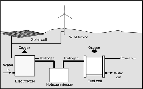
Once manufactured and stored, hydrogen can be converted back into electricity in a number of ways. It can be burned like natural gas, although the combustion temperature is generally higher than for the former. However, most gas turbines, piston engines, and gas-fired boilers can easily be adapted for its use. When burned in this way it produces only water as a by-product. Alternatively, and possibly most efficiently, hydrogen can provide the fuel for a fuel cell system as illustrated in Figure 10.9. For a future energy economy based on hydrogen, this offers one of the most promising solutions with 60% efficiency achievable in a simple fuel cell and perhaps 70–75% with a hybrid system.
Performance Characteristics
When used as an energy storage medium within an electricity system, hydrogen will generally be used as fuel in a conventional or fuel cell power plant and generally cannot be brought into service as rapidly as some of the fast-acting storage systems discussed above. It should, therefore, be considered as a system of energy arbitrage rather than for grid support.
The main drawback today of hydrogen storage is the round cycle efficiency. With an electrolyzer operating at 90% efficiency and a power plant converting it back into electricity with perhaps 60% efficiency, the best roundtrip efficiency that can be expected is 54%, much lower than other storage systems discussed earlier. Such low efficiency may be tolerable in a renewable energy storage system, such as a wind–hydrogen storage unit where the wind energy must otherwise be shed. It is unlikely to be considered sufficiently efficient for generation from off-peak grid power in most other circumstances if there is an alternative available.
Costs
Since hydrogen energy storage as an electrical energy storage medium has yet to be tested, there are no realistic costs available for practical systems. If it is to be of use it would need to be able to compete with the high storage capacity technologies such as pumped storage hydropower, CAES, or large battery storage.