
Piston Engine–Based Power Plants
Abstract
Piston engines are the largest group of thermodynamic heat engines in use today. Those used for power generation are invariably derived from other types used for transportation. There are two main types of piston engine: the spark-ignition engine and diesel engine. The diesel engine is the more efficient but it also generates more pollution. There are also two common engine cycles: the two-stroke cycle and four-stroke cycle. The latter is most commonly found in engines used for electricity production. In most engines there is a compromise between high efficiency and high emission levels and big power plants generally require emission control systems. Modified engines such as the dual-fuel engine attempt to achieve both high efficiency and low emissions. Piston engines can operate on a range of fuels but many modern units burn natural gas. Another category of engine, the Stirling engine, can be used for solar generation.
Piston engines or reciprocating engines (the two terms are often used interchangeably) are by a wide margin the largest group of thermodynamic heat engines in use around the world. Their applications range from model airplanes to lawn mowers, and they include all the automotive power plants found in motorcycles, cars, trucks, and many other sorts of heavy machinery. They also power locomotives, ships, and many small aircraft, and they provide stationary electrical power and combined heat and power to numerous sites across the globe.
The number in use is enormous; the United States alone produces more than 35 million each year. Engines vary in size from less than 1 kW (model engines can be a few watts) to 65,000 kW. They can burn a wide range of fuels including natural gas, biogas, LPG, gasoline, diesel, biodiesel, heavy fuel oil, and even coal. They are manufactured all over the globe and there is a large global base of expertise in their maintenance and repair.
In line with the wide range of engines available, the power generation applications of piston engines are enormously varied. Small units can be used for standby power or for combined heat and power in homes and offices. Larger standby units are often used in situations where a continuous supply of power is critical, such as in hospitals or to support highly sensitive computer installations like for air traffic control and the many server farms around the world. Commercial and industrial facilities use medium-size piston engine–based combined heat and power units for base-load power generation. Large engines, meanwhile, can be used for base-load, grid-connected power generation, while smaller units form one of the main sources of base-load power to isolated communities with no access to an electricity grid.
The piston engines used for power generation are almost exclusively derived from similar engines designed for motive applications. Smaller units are normally based on car or truck engines, while the larger engines are based on locomotive or marine engines. Performance of these engines vary. The small engines are usually cheap because they are mass produced, but they have relatively low efficiencies and short lives. Larger engines tend to be more expensive, but they will operate for much longer. Large, megawatt-scale engines are among the most efficient prime movers available,1 with simple cycle efficiencies approaching 50%.
There are two main types of reciprocating engines: the spark-ignition engine and the compression or diesel engine. The latter was traditionally the most popular for power generation applications because of its higher efficiency. However, it also produces high levels of atmospheric pollution, particularly nitrogen oxide. As a consequence, spark-ignition engines burning natural gas have become the more popular units for power generation, at least within industrialized nations. A third type of piston engine, called the Stirling engine, is also being developed for some specialized power generation applications. This engine is novel because the heat energy used to drive it is applied outside the sealed piston chamber.
Internal combustion engines
The common feature of all reciprocating engines is a cylindrical chamber housing a piston. In its most basic form the engine comprises a single cylinder sealed at one end and open at the other end. A cylindrical-shaped disk of metal, the piston, is designed to fit closely within the cylinder to seal the open end, and this piston can move backwards and forwards easily within the cylinder. This it does in response to the pressure changes in the gas contained within the cylinder at various stages in the engine cycle. Meanwhile, air and fuel can be admitted into the sealed end of the cylinder, and exhaust gases removed after combustion through moveable valves. The outside of the piston is attached via a hinged lever to the main drive shaft of the engine. Movement of the piston in and out of the cylinder is converted via this hinged linkage into rotary motion of the main shaft and this rotary motion is used to derive power or electricity.
To convert chemical energy contained within a fuel into mechanical energy, an air–fuel mixture is admitted into the cylinder of the engine and ignited, causing a controlled explosion and a high-pressure impulse from which the power of the engine is derived. The pressure impulse forces the gases in the cylinder to expand, pushing the piston to the limit of its movement. This controlled explosion gives the engines its common name: the internal combustion engine.
There are two main types of internal combustion engine: the spark ignition engine and the diesel or compression-ignition engine, each defined by the way in which fuel is admitted into the engine cylinder and how ignition of the air–fuel mixture is initiated. The two types of engine can be further subdivided according the engine cycle they employ. Two are common: the two-stroke cycle and the four-stroke cycle. Internal combustion engines account for virtually all the reciprocating engines in use around the world.
Of the two common engine cycles, the four-stroke cycle is the most commonly used, particularly for small- and medium-size engines. A two-stroke cycle is employed is some very small engines because it can provide a high power-to-weight ratio. It is also often used in very large engines since it is capable of high efficiency and tolerating very poor fuels.
Both cycles are broadly similar in concept to the principle employed in the gas-turbine engine described in Chapter 4. Air is compressed and then fuel added and ignited, generating a hot, high-pressure gas from which energy can be extracted in the form of mechanical work. However, whereas the gas-turbine engine is continuously compressing air, mixing it with fuel and igniting the mixture, the piston engine carries these processes out sequentially.
Engine Cycles
The internal combustion engine is a thermodynamic heat engine, and as such belongs to the same category as steam turbines and gas turbines. However, the physical nature of the reciprocating engine is very different to that of the turbines. The reciprocating engine principle was developed in the latter half of the 19th century, though some primitive engines were in existence before that. Nikolaus Otto is generally credited with building the first four-stroke internal combustion engine in 1876. In doing so, he established the principle still in use today.
The Otto cycle engine employs a spark to ignite a mixture of air and, traditionally, gasoline2 compressed by the piston within the engine cylinder. This spark ignition causes an explosive release of heat energy that increases the gas pressure in the cylinder, forcing the piston outwards as the gas tries to expand. This explosion is the source of power, its force on the piston turning the crankshaft to generate rotary motion.
The Otto cycle was modified by Rudolph Diesel in the 1890s. In his version, air is compressed in a cylinder by a piston to such a high pressure that its temperature rises above the ignition point of the fuel, which is then introduced into the chamber and ignites spontaneously without the need for a spark. This represents a simplification of the Otto cycle but is not without its complications, particularly from an emissions perspective.
In a four-stroke engine each piston of the engine—and there can be a large number depending on the particular engine type and application—is equipped with at least two valves: one to admit air or an air–fuel mixture, and a second to exhaust spent gases after ignition. The opening and closing of these valves is mechanically synchronized with the movement of the piston backwards and forwards.
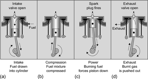
The four-stroke cycle derives its name from the four identifiable movements of the piston in the chamber, two of expansion and two of compression, for each full power cycle. Starting with the piston at the top of its chamber, and the chamber empty, the first stroke is an intake stroke in which either air (diesel cycle) or a fuel and air mixture (Otto cycle), is drawn into the piston chamber by movement of the piston to expand the volume of the enclosed space (Figure 5.1) and the air or fuel–air valve is open. This valve closes at the end of the first stroke. The second stroke is a compression stroke during which the gases in the cylinder are compressed by the piston returning toward the top of its chamber. In the case of the Otto cycle, a spark ignites the fuel–air mixture at the top of this second stroke, creating an explosive expansion of the compressed mixture that forces the piston down again. This is the power cycle. In the diesel cycle fuel is introduced through a separate nozzle close to the top of the compression stroke, igniting spontaneously in the hot gas with the same effect. After the power stroke, the fourth stroke is the exhaust stroke during which the exhaust gases are forced out of the piston chamber through the second valve, which is now open. This closes at the end of the fourth stroke and the cycle begins again. In both spark-ignition and diesel engines a large flywheel attached to the crankshaft stores angular momentum generated by the power stroke and this provides sufficient momentum to carry the crankshaft and piston through the three other stokes required for each cycle.
The shaft of an engine that is fitted with a single piston and cylinder will receive a power impulse once every two rotations, leading to a relatively uneven transfer of power. However, if the engine has multiple cylinders, the cycle of each can be staggered relative to the others so that they deliver their power sequentially, leading to a much more even rotational motion. For a four-stroke engine it is normal for four (or a multiple of four) pistons to be attached to the crankshaft, with one of each set of four timed to produce a power stroke while the other three move through different stages of their cycles. The introduction of fuel and air and the removal of the exhaust gases are then controlled by valves that are mechanically timed to coincide with the various stages of the cycle on each cylinder.
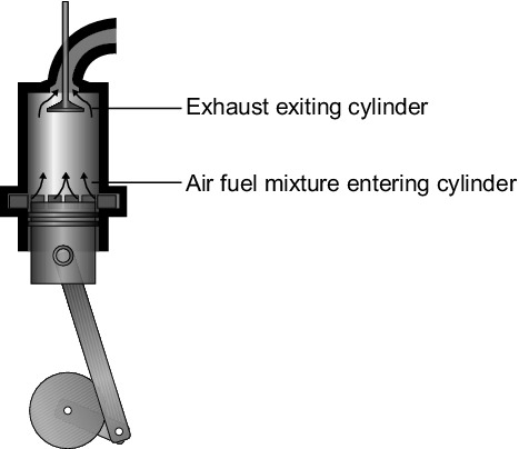
In a two-stroke engine, intake and exhaust strokes are not separate. Instead, fuel is forced into the piston chamber (intake) from an opening in the crankshaft casing toward the end of the power stroke, pushing out the exhaust gases through a second opening at the top of the chamber. The same stroke then compresses the fuel–air mixture within the cylinder, the exhaust port having been closed by movement of the piston. This exhaust–compression stroke is then followed by ignition of the fuel and a power–expansion stroke, then a repeat of the cycle (Figure 5.2).
Two-stroke engines are simpler than four-stroke engines because they do not require valves. In addition, power is delivered by each cylinder at each revolution of the shaft rather than once every two revolutions. This means they can deliver more power for a similar weight.
Engine Size and Engine Speed
The speed at which a piston engine operates will usually depend on its size. In general, small units operate at the highest shaft rotational speed and large units at the lowest shaft speed. In addition, in most situations a piston engine–based power unit will have to be synchronized to an electricity grid operating at 50 Hz or 60 Hz, so the engine speed will also be determined by one or the other of these rates. So, for example, a 50 Hz high-speed engine will typically operate at 1000 rpm, 1500 rpm, or 3000 rpm, while the equivalent 60 Hz machine will operate at 1200 rpm, 1800 rpm, or 3600 rpm. These speeds allow the generators attached to the engines to synchronize with the grid operating frequency.
Engines are usually classified according to speed into one of three groups, high speed, medium speed and slow speed engines. High speed engines are the smallest and operate up to 3600 rpm. The largest slow speed engines may run as slow as 50 rpm. Typical speed and power ranges for each type of engine are shown in Table 5.1.
Table 5.1
Piston Engine Classification by Size and Speed
| Engine Size | Engine Speed (rpm) | |
| High speed | 1 kW–8.5 MW | 1000–3600 |
| Medium speed | 1 MW–35 MW | 275–1000 |
| Slow speed | 2 MW–65 MW | 50–275 |
Source: Technology Characterization: Reciprocating Engines, U.S. Environmental Protection Agency, 2002.
Engine performance varies with speed. High-speed engines provide the greatest power output as a function of cylinder size, and therefore the greatest power density. However, the larger, slower engines are more efficient and last longer. Thus, the choice of engine will depend very much on the application for which it is intended. Large and slow- or medium-speed engines are generally more suited to base-load generation, but it may be more cost effective to employ high-speed engines for backup service where the engines will not be required to operate for many hours each year.
In addition to standby service or continuous output base-load operation, piston engine power plants are good at load following. Internal combustion engines operate well under part-load conditions. For a gas-fired spark-ignition engine, output at 50% load is roughly 8–10% lower than at full load. The diesel engine performs even better, with output barely changing when load drops from 100% to 50%.
Spark-ignition engines
Spark-ignition engines are capable of burning a variety of fuels, including gasoline, propane, biogas, and landfill gas. In practice, however, many of these engines burn natural gas when used for power generation applications because of the lower emissions. These power-generating units are generally four-stroke engines and they are available in sizes from less than 1 kW up to around 6.5 MW (Table 5.2).
Table 5.2
Four-stroke Engine Performance Parameters
| Diesel Engine | Spark-ignition Engine | |
| Typical size range | 1 kW–65 MW | 1 kW–6.5 MW |
| Efficiency | 20–48% | 28–42% |
| Compression ratio | 14:1 to 25:1 | 8:1 to 12:1 |
The spark-ignition engine uses a spark plug to ignite the fuel–air mixture that is admitted to each cylinder of the engine. In the simplest case this spark plug is located in the top of the cylinder and directly ignites the mixture within the cylinder. The composition of the fuel–air mixture in the cylinder may be close to the stoichiometric ratio required for complete combustion of the fuel, but more often it will contain a significant excess of air. More technically complex engines can use a preignition chamber in which a small amount of a fuel–air mixture rich in fuel is admitted and ignited. This preignition then spreads into the main cylinder where a fuel–air mixture containing a much greater proportion of air is ignited.
In common with all thermodynamic heat engines, the efficiency that a reciprocating engine can achieve increases with the temperature of the working fluid: air. For a spark-ignition engine the highest cylinder temperature is reached when the air-to-fuel ratio is around 16:1, the ratio at which a stoichiometric amount of oxygen is available to react with the fuel. An engine that operates with this air–fuel mixture is described as a rich-burn engine. A rich mixture leads to the highest temperature but it also leads to the greatest formation of nitrogen oxide, as well as significant amounts of carbon monoxide and unburned hydrocarbon particles as a result of incomplete combustion of some of the fuel. Under most circumstances, therefore, engines operating on a rich mixture will require emission control systems to limit the release of these potential pollutants.
If engine emissions are to be reduced during combustion, then the combustion temperature must be lowered and a greater amount of oxygen introduced to allow complete combustion of the fuel. Such engines are described as lean-burn engines and can operate with an air-to-fuel ratio between 20:1 and 50:1, significantly higher than in the rich-burn engine. The greater proportion of air lowers the overall combustion temperature (there will be less fuel entering the combustion chamber in the lean mixture), reducing the production of nitrogen oxide from nitrogen in the air, and provides the conditions for much more complete combustion of the fuel. This will reduce the amounts of carbon monoxide and unburned hydrocarbons in the exhaust gases. Against this, the lower temperature reduces overall efficiency. Lean-burn engines achieve a typical efficiency of only 28% (LHV),3 compared to up to 42% (LHV) for a rich-burn engine. An engine tuned for maximum efficiency will produce roughly twice as much nitrogen oxide as one tuned for low emissions. Typical nitrogen oxide emission levels for spark-ignition engines are 45 ppmV to 150 ppmV.
The compression ratio of a spark-ignition engine (the amount by which the air–fuel mixture is compressed within the cylinder) is normally limited to a maximum between 9:1 and 12:1 to prevent the mixture from becoming too hot and spontaneously igniting, a process known as knocking. Lean natural gas–air mixtures have a much higher resistance to knocking than stoichiometic mixtures and can tolerate higher compression ratios than gasoline.
Diesel engines (compression engines)
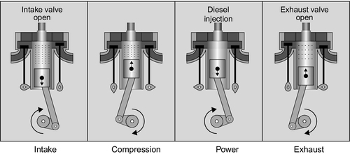
Whereas a spark-ignition engine draws a fuel–air mixture into the cylinder during the first stroke of the four-stroke cycle, in a diesel engine only air is admitted at this stage (Figure 5.3). This air is then compressed much more highly during the succeeding compression stroke than would be the case with a spark-ignition engine, with compression ratios of up to 25:1 typical. When air is compressed adiabatically in this way (just like the air being compressed in a bicycle pump), the compression generates heat so that the air becomes much hotter. In the diesel engine the compression ratio is chosen so that the air temperature rises so high that it is above the ignition temperature of the fuel, in this case diesel. Fuel is admitted into the chamber under pressure toward the top of the compression stroke, when it then ignites spontaneously.
The temperature inside the cylinder of a diesel engine during ignition rises much higher than the temperature in a spark-ignition engine. As a consequence the production of nitrogen oxide is much higher. Typical levels are 450 ppmV to 1800 ppmV, or 10 times higher than for the equivalent spark-ignition engine (see Table 5.3 later, but note that as shown in Table 5.4 that they can rise even higher). Diesel engines, therefore, require extensive emission control systems if they are to comply with air-quality regulations, particularly when the units are operating in an urban environment. Against this, diesel engines are capable of burning biodiesel, a carbon dioxide–emission neutral fuel. This can be attractive in some situations.
Table 5.3
Emissions of Nitrogen Oxide from Internal Combustion Engines
| Emissions (ppmV) | Emissions (g/kWh) | |
| High-speed and medium-speed diesel engine | 450–1800 | 7–20 |
| Spark-ignition natural gas engine | 45–150 | 1–3 |
Source: Technology Characterization: Reciprocating Engines, U.S. Environmental Protection Agency, 2008.
Table 5.4
Range of Emissions from Diesel Engines
| Emissions | Emission Range |
| Nitrogen oxide | 50–2500 ppmV |
| Carbon monoxide | 5–1500 ppmV |
| Particulate matter | 0.1–0.25 g/m3 |
| VOCs | 20–400 ppmV |
| Sulfur dioxide | 10–150 ppmV |
Source: Nett Technologies.
The efficiency of the diesel engine ranges from 30% (HHV) for small engines to 48% (HHV) for the largest engines. The highest efficiency yet achieved is 52% for a 67 MW marine diesel engine. Higher temperatures could conceivably produce higher efficiency, but as with other types of thermodynamic engines, materials will be the limiting factor. Diesel engines can be built to larger sizes than spark-ignition engines, with high-speed machines available in sizes up to 4 MW and slow-speed diesels up to 65 MW. Large, slow-speed engines can have enormous cylinders. For example, a nine-cylinder, 24 MW engine used in a power station in Macau has cylinders with a diameter of 800 mm.
Diesel engines can burn a range of diesel fuels including both oil-derived fuels and biofuels. Smaller, high-speed engines normally use high-quality distillate but the large, slow-speed engines can burn very low-quality heavy fuel oils, which require a much longer combustion time to burn completely. These fuels tend to be dirty and plants burning them usually require additional emission mitigation measures.
Dual-fuel engines
The large disparity in efficiency between a spark-ignition engine and a diesel engine has prompted engine developers to search for a way on achieving the efficiency of a diesel engine in a natural gas–fired spark-ignition engine. This is the origin of the dual-fuel engine, which has been the most successful of these hybrids (Figure 5.4).
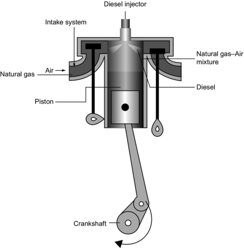
A dual-fuel engine is an engine designed to burn predominantly natural gas but with a small percentage of diesel as a pilot fuel to start ignition. The engines operate on a cross between the diesel and the Otto cycles. In operation, a natural gas–air mixture is admitted to the cylinder during the intake stroke, then compressed during the compression stroke. At the top of the compression stoke the pilot diesel fuel is admitted and ignites spontaneously, igniting the gas–air mixture to create the power expansion. Care has to be taken to avoid spontaneous ignition of the natural gas–air mixture, but with careful design the engine can operate at close to the compression conditions of a diesel engine, with a high-power output and high efficiency, yet with the emissions close to those of a gas-fired spark-ignition engine. However, efficiency tends to fall and emissions of unburned hydrocarbons and carbon monoxide rise at part load.
Typical dual-fuel engines operate with between 1% and 15% diesel fuel. Since a dual-fuel engine must be equipped with diesel injectors, exactly as if it were a diesel engine, a dual-fuel engine can also burn 100% diesel if necessary, though with the penalty of much higher emissions.
Stirling engines
Whereas fuel combustion takes place within the cylinders of an internal combustion engine, the heat energy used to drive a Stirling engine is applied outside the cylinders, which are completely sealed. The engine was designed by a Scottish Presbyterian minister, Robert Stirling, who received his first patent in 1816.
The original Stirling engines used air within the cylinders and were called air engines but modern Stirling engines usually employ helium or hydrogen. Both gases are capable of absorbing a large quantity of heat rapidly, a key advantage for an external combustion engine. The gas within the closed cycle system will be pressurized to up to 20 MPa, roughly 200 times atmospheric pressure.
The simplest form of Stirling engine consists of two cylinders, each sealed with a piston but with the sealed end of each cylinder linked so that the working fluid, which is sealed within the two cylinders, can move from one to the other during the cycle (Figure 5.5). The heat source that provides the energy to drive the cycle is applied to one cylinder while a cold sink, usually ambient air, is applied to the second. The two cylinders are linked, externally, too, by a system of levers that ensures their movements are synchronized. There will usually be a flywheel attached to the system to store energy from the power stroke, one of four in the cycle, in the form of angular momentum to drive all four stages.
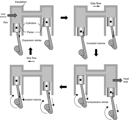
In the first part of the cycle, the power stroke for the working fluid is contained in the hot cylinder and the cold cylinder piston is at the top of its cylinder, which is empty. The heat that is continuously applied to the hot cylinder causes the working fluid to heat up and increase in pressure and expand, forcing the piston to move toward the bottom of the cylinder. During this part of the cycle the cold cylinder piston remains stationary. The expansion of the hot gas provides the power that drives the engine through its whole cycle.
In the second stage, the cold cylinder piston starts to move toward the bottom of its cylinder while at the same time the hot cylinder piston moves to the top of its cylinder, causing the working gas to move, essentially at constant pressure, from one cylinder to the other. However, as the gas is drawn into the cold cylinder it becomes cooled and the pressure falls.
In the third stage of the cycle the cold cylinder piston starts to move toward the top of its cylinder again, compressing the cold gas and generating some heat in the process, which is removed by the cold sink. During this stage the hot cylinder piston remains stationary.
The final stage, another essentially constant pressure stage, involves the cold cylinder moving to the top of its cylinder, forcing all the working fluid into the hot cylinder, while the piston in the hot cylinder starts to move down to accommodate the cold working fluid. As this begins to become heated by the hot source, the cycle starts again. In essence, the full cycle involves the expansion and then the contraction of the working fluid.
Actual Stirling engines are generally more complex than this. Some replace one cylinder by a device called a displacer, and the working fluid often passes through a recuperator between the hot and cold cylinders so that energy otherwise lost can be captured and reused. This allows the cycle to approach the theoretical Carnot cycle efficiency for a heat engine, and high efficiency is one of the great attractions of the Stirling engine.
The other great advantage of the Stirling engine is that the heat energy is applied externally. Thus the energy can, in theory, be derived from any heat source. Stirling engines have been used to exploit solar energy and for biomass applications. However, their use is not widespread. Typical engine sizes in use and development range from 1 kW to 150 kW. In solar thermal applications a Stirling engine could theoretically achieve close to 40% energy conversion efficiency. The best so far recorded is just over 31%, which is still high for solar conversion.
Cogeneration
When an internal combustion engine is used to generate electricity, a large part of the energy supplied to the engine in the form of fuel emerges as heat in the exhaust from the engine or is dumped into the atmosphere by engine cooling systems. If this heat can be captured it can be utilized for space heating or for heating water, potentially making the energy usage much more efficient.
The efficiency of piston engine–based power generation varies from 25% for small engines to close to 50% for the very largest engines. This means that between 50% and 75% of the fuel energy actually emerges as waste heat. There are four primary sources of waste heat in an internal combustion engine: engine exhaust, engine case cooling water, lubrication oil cooling water, and, where one is fitted, turbocharger cooling.4 Each of these can be used as a source of heat in a reciprocating engine cogeneration system.
The exhaust gas contains up to one-third of the fuel energy and 30–50% of the total waste heat from the engine. Exhaust heat is not normally captured but it is straightforward to fit a heat-recovery system to the exhaust of an engine if the heat is required. The exhaust temperature is typically between 370 °C and 540 °C. This is sufficiently high that it can be used to generate medium-pressure steam if required. Otherwise, it can be used to generate hot water.
The main engine case cooling system can capture up to 30% of the total energy input. Cooling water exits the cooling system at up to 95 °C.5 In a cogeneration system this will be passed through a heat exchanger to provide a source of hot water. Engine oil and turbocharger cooling systems will provide additional energy that can also be used to supply hot water.
If all the heat from the exhaust and cooling systems of an engine is exploited, around 70–80% of the fuel energy can be used. However, this can generally only be fully exploited when there is a need for hot water. Engine exhaust gases have also been used directly for drying in some situations.
Since cooling systems are fitted to internal combustion engines whether the waste heat is exploited or not, the use of these systems in combined heat and power applications offers a logical extension of their application. Cogeneration systems based on small engines can provide power, space heating, and hot water to homes and commercial offices, while large engines can produce power and low-grade process heat for small industrial operations. The economics of these systems can be quite favorable where there is a use for the waste heat. As a consequence, the cogeneration market, particularly for small systems, is buoyant and is likely to become more so if fuel costs continue to rise.
Combined cycle
The waste heat from the exhaust of an internal combustion engine is generally hot enough to generate medium-pressure steam. In the case of small engine installations, steam production is not normally an economical option unless there is a local use for low-quality steam. In the case of a large diesel installation, however, the engine exhaust can be used to generate steam in a boiler, steam that can drive a steam turbine to produce additional energy. This forms the core of a diesel engine–based combined cycle plant.
Diesel engine combined heat and power systems are rare because they are generally only economical on very large engines. Typical of this sort of application is a generating plant that was installed in Macau in 1987. This plant was equipped with a slow-speed diesel engine with a capacity of 24.4 MW. The engine exhaust was fitted with a waste heat boiler and steam turbine that could generate an additional 1.34 MW when the engine was operating at full power, thus contributing around 5% of the plant output. As a result of this and other measures a fuel-to-electricity conversion efficiency of close to 50% was achieved.
Large engines of this type are frequently derived from marine engines and the original engines upon which they are based are not normally optimized for combined cycle operation. In particular, the cooling system is designed to keep the engine as cool as possible. For best combined cycle performance, however, it is preferable to run the engine as hot as possible, because the higher the exhaust gas temperature, the more efficient the steam turbine cycle. High-temperature operation can also improve engine efficiency because the potential thermodynamic efficiency will increase with operating temperature.
Combined cycle performance of a large diesel engine can, therefore, be improved by modifying engine components such that they can operate continuously at a higher temperature. Such modifications may require more expensive materials capable of withstanding the more extreme conditions. For example, the top of the piston may be made from an alloy that allows it to remain uncooled while exhaust valves are treated with advanced coatings able to resist the high exhaust gas temperature.
These modifications allow a higher temperature exhaust that can be used to generate higher-quality steam to drive a steam turbine. With these measures it may be possible to achieve a fuel-to-electricity conversion efficiency of close to 55%. This is the efficiency target for a plant in Wasa, Finland, installed in 1998. The plant has two 17 MW diesel engines and a single steam turbine. Efficiency in this case is improved by using seawater cooling for the steam turbine condenser. The additional expense of the waste heat recovery and steam turbine will generally only prove cost effective if the engine is to be used for base-load operation.
Emission control
Piston engine power units generally burn fossil fuels, and the environmental considerations that need to be taken into account are exactly the same as those that affect all coal-, oil-, and gas-fired power plants—that is, all the emissions resulting from fuel combustion. In the case of internal combustion engines the main emissions are nitrogen oxide, carbon monoxide, and volatile organic compounds (VOCs). Larger diesel engines, particularly those burning heavy diesel fuel, will also produce particulate matter and some sulfur dioxide.
Nitrogen oxide is formed primarily during combustion by a reaction between nitrogen and oxygen in the air mixed with the fuel. This reaction takes place more rapidly at higher temperatures. In lean-burn gas engines where the fuel is burned with an excess of air, temperatures can be kept low enough to maintain low nitrogen oxide emissions. The diesel cycle depends on relatively high temperatures, and as a consequence of this, produces relatively high levels of nitrogen oxide. Table 5.3 compares emissions from the two types of engine.
When the fuel in an internal combustion engine is not completely burned the exhaust will contain both carbon monoxide and some unburned hydrocarbons. Carbon monoxide is hazardous at low levels and its emissions are regulated like those of nitrogen oxide. Unburned hydrocarbons are classified as VOCs and their emissions are also controlled by legislation.
Natural gas contains negligible quantities of sulfur so gas engines produce no sulfur dioxide. Diesel fuels can contain sulfur. Small- and medium-size diesel engines generally burn lighter diesel fuels that contain little sulfur. Larger engines can burn heavy residual oils that are comparatively cheap but often contain significant levels of sulfur. Since sulfur can damage the engine, it is normal to treat this type of fuel first to remove most of the sulfur.
Liquid fuels may produce particulate matter in an engine exhaust, the particles derived from ash and metallic additives. Incomplete combustion of heavy fuel can also lead to the emissions of particulate matter.
Nitrogen Oxide
The most serious exhaust emissions from a piston engine is nitrogen oxide. Engine modifications that reduce the combustion temperature of the fuel, such as the use of a lean-fuel mixture described earlier, provide the first step in reducing these emissions. Natural gas engines designed to burn a very lean fuel (excess air) provide the best performance: 45–150 ppmV or 1–3 g/kWh. Diesel engines present a greater problem because of the higher combustion temperature (Table 5.4).
An additional technique that is being applied to internal combustion engines to reduce nitrogen oxide is exhaust gas recirculation. This involves taking some of the exhaust gas and mixing it with the air used to feed the engine. The effect is to reduce the overall oxygen concentration and thereby reduce the combustion temperature. This reduces nitrogen oxide production but will also reduce engine efficiency. However, depending on the regulatory regime, all types of internal combustion engines may require some additional form of post-combustion nitrogen oxide emission control.
For small gasoline engines a simple catalytic converter of the type used in automobiles is often the most effective solution. However, this type of system cannot be used with diesel or with lean-burn engines. New catalysts for use with lean-burn engines are currently under development. Where a catalytic converter can be used, nitrogen oxide reduction is around 90% or more.
Automobile-style catalytic converters are a relatively expensive means of reducing nitrogen oxide emissions. For large engines, the more economical alternative is to use a selective catalytic reduction (SCR) system that can be applied to both stationary engines and large truck engines. An SCR system also employs a catalyst, but in conjunction with a chemical reagent, normally ammonia or urea, which is added to the exhaust gas stream before the emission control system. The reagent and nitrogen oxide react on the catalyst and the nitrogen oxide is reduced to nitrogen. This type of system will reduce emissions by 80% to 90%. However, care has to be taken to balance the quantity of reagent added so that none emerges from the final exhaust to create a secondary emission problem.
Carbon Monoxide, VOCs, and Particulates
The emission of carbon monoxide, VOCs, and some particulate matter can be partially controlled by ensuring that the fuel is completely burned within the engine. This is simplest in lean-burn engines but conditions within these engines compromises efficiency. With all engines, careful control of engine conditions and electronic monitoring systems can help maintain engine conditions at their optimum level. Old engines as they become worn can burn lubrication oil, causing further particulate emissions.
For larger engines, particularly diesel engines, engine control systems also will not maintain emissions sufficiently low to meet statutory emission standards. In this case an oxidation catalyst will be needed to treat the exhaust gases. When the hot gases pass over the oxidation catalyst, carbon monoxide, unburned hydrocarbons, and carbon particles are oxidized by reacting with oxygen remaining in the exhaust gases, completing the combustion process and converting all the materials into carbon dioxide.
Sulfur Dioxide
Sulfur emissions can be found in diesel engines that burn fuel containing sulfur. Many engines now burn low-sulfur fuels with less than 0.05% sulfur content. However, some diesels and the heavy fuel oils that very large engines burn may contain significant amounts of sulfur. The latter may contain as much as 3.5% sulfur. The best way of controlling sulfur emissions from internal combustion engines is to remove the sulfur from the fuel before use. However, in the worst case a sulfur capture system can be fitted. This is likely to be similar to the scrubbing tower used in a coal-fired power plant but at a much smaller scale. The use of such a system adds to both capital and maintenance costs and affects plant economics. It is only likely to be cost effective in the very largest reciprocating engine-based power plants.
Carbon Dioxide
Internal combustion engines, in common with all heat engines that burn carbon-based fuel, generate carbon dioxide, which is released in the exhaust gases leaving the engine. The relative amount produced during electricity generation depends on the efficiency of the engine. A large, high-efficiency diesel engine operating at close to 50% efficiency will produce significantly less carbon dioxide for each unit of electricity it generates than a small gasoline engine operating at perhaps 20% efficiency.
Currently the only way of effectively eliminating carbon dioxide emissions from such engines is to run them on a biofuel such as ethanol or biodiesel that has been derived from plants. The principle here is that although the combustion of the fuel will still produce carbon dioxide, the regrowth of the plants that were used to produce the fuel will absorb the same amount of carbon dioxide from the atmosphere, so that for a full cycle of growth, fuel production and combustion, the net amount of carbon dioxide added to the atmosphere is zero.
Research is underway to develop systems to capture carbon dioxide from the exhaust of reciprocating engines and a variety of techniques are being explored based on some form of post-combustion capture. Whether such systems will ever be used extensively on reciprocating engines seems doubtful since the cost is likely to be prohibitive. However, for very large power generating systems it might eventually be both technically feasible and economical.
Cost of reciprocating engine-based power generation
The economics of power generation based on reciprocating engines depends to a large extent on the use to which the engine is to be put. The cheapest engines available are small petrol-driven engines based on car engines, which are manufactured in large numbers each year. These engines can be purchased as stand-by generators for as little as $250/kW. Such engines are cheap so they are well suited to applications where they will only be required to operate infrequently. However, they are expensive to run since their energy conversion efficiency is relatively low and they have short lifetimes, requiring the extensive and regular maintenance of an automotive engine.
Large engines designed for power generation are generally much more expensive. Natural gas–fired engines of around 300 kW are likely to cost around $2000/kW. While detailed cost data tends to be proprietary, evidence suggests that capital costs drop as engine size rises into the megawatt and multi-megawatt range. All these larger engines are built to be able to operate for long periods between maintenance. They are generally more efficient than the smaller engines too, so their operating costs are lower.
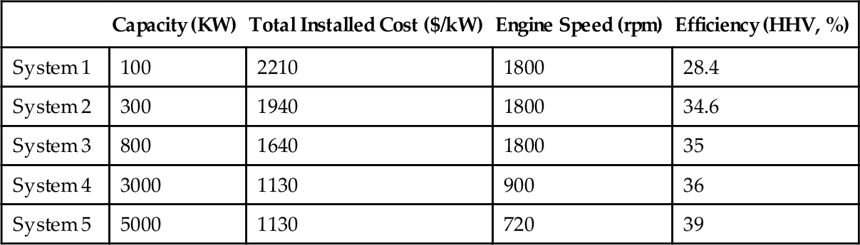
Table 5.5 shows figures for a range of generic power generation systems based on reciprocating engines that illustrates these trends. The costs in this table are in year 2010 U.S. dollars. The smallest system in the table, with a generating capacity of 100 kW, is based on a high-speed engine operating at 1800 rpm. Efficiency is 28.4% and the cost is $2210/kW. At the other end of the scale a 5 MW system is based on a medium-speed engine running at 720 rpm. This has an efficiency of 39% and an installed cost of $1130/kW.
Table 5.5
Cost and Efficiency Figures for a Series of Reciprocating Engine Systems
| Capacity (KW) | Total Installed Cost ($/kW) | Engine Speed (rpm) | Efficiency (HHV, %) | |
| System 1 | 100 | 2210 | 1800 | 28.4 |
| System 2 | 300 | 1940 | 1800 | 34.6 |
| System 3 | 800 | 1640 | 1800 | 35 |
| System 4 | 3000 | 1130 | 900 | 36 |
| System 5 | 5000 | 1130 | 720 | 39 |
Source: Technology Characterization: Reciprocating Engines, U.S. Environmental Protection Agency, 2008.
The cost effectiveness of most systems such as those in Table 5.5 will depend on whether they can be used to supply heat as well as electrical power. All the systems in the table were assessed for their cogeneration efficiency when providing hot water. The most efficient were systems 2 and 3 with overall efficiencies of 78% and 79%, respectively. The least efficient was system 4 at 73%.
The cost of Stirling engines is much higher than for most internal combustion engines because they are not produced in large enough quantities to bring about the economy of volume production. Estimates vary widely, from as low as $2000/kW to as high as $50,000/kW.