
We are reaching the final and most important phase of the on-premise installation of Oracle Fusion Applications, which is the provisioning of Fusion Applications nodes. We already have an Identity Management environment up and running that provides identity and policy stores for our Fusion Applications environment. Additionally, we have the Fusion Applications database prepared which will now host the Fusion Applications-related transaction data. In this chapter, we will prepare the Fusion Applications host by installing the provisioning framework and creating the provisioning response file. This response file will be later used for provisioning the Fusion Applications environment. Since the provisioning process relies completely on the values entered in the response file, any incorrect values may lead to failure of the installation.
Installing Provisioning Framework
Similar to what we saw with the database nodes, installing the Fusion Applications provisioning framework on all the application nodes of the topology is a prerequisite for the provisioning process. This framework includes the Graphical Provisioning wizard as well as command-line tools that are required to run the provisioning phases on the primary and secondary hosts.
As you know, we have selected two-tier topology with four nodes. So we have single node only for Fusion Applications middle tier and web tier components. Hence, we will install the Fusion Applications provisioning framework only on one node—FAHOST. Note if you have application or web multiple nodes in the selected topology, you must install the provisioning framework on all nodes.
Note
Since we have already covered installing the provisioning framework on a Fusion Applications database node in a previous chapter, we will not go into the details of the steps here. If you want a refresher, follow the steps and screens in Chapter 8.
As the Fusion Applications provisioning framework installer is available in the Installer Repository under the directory named faprov, start the installation of Fusion Applications provisioning framework from <REPOSITORY_LOCATION>/installers/faprov/Disk1. For example:
[fusion@idmhost ∼]$ cd /stage/installers/faprov/Disk1/
[fusion@idmhost Disk1]$ ./runInstaller
...
Specify the JRE/JDK location ( Ex. /home/jre ), <location>/bin/java should exist : /stage/jdk6
Since the installation of provisioning framework is identical to what we saw in Chapter 8, you can run through the wizard by following the screens and steps shown in Chapter 8 and finish the installation. Here also we will install the framework at /app/fusion/provisioning.
Fusion Applications Provisioning Framework Directory Structure
We skipped the explanation of the Fusion Applications provisioning framework directory structure in the last chapter since most of its subdirectories are relevant to the applications provisioning but not to the database installation. In this section, we will explore the importance of each subdirectory of the Fusion Applications provisioning framework with respect to the applications provisioning process.
Figure 9-1 shows the major directories of importance under the provisioning framework home that are accessed during the various tasks of the provisioning process.

Figure 9-1. Fusion Applications provisioning framework directory structure
Let’s explore the role of each of these subdirectories of the provisioning framework.
bin: This is the main directory that you will refer to since it contains all the scripts to run the Provisioning wizard, including provisioningWizard.sh, the command-line tools like runProvisioning.sh, and the environment setup scripts like envConfig.sh and the Windows equivalents in .bat format. The directory also contains various configuration files specific to the execution of these scripts; for example, logging.properties, prov-logging-config.xml, and so on.
lib: As the name suggests, this directory contains all the required Java class libraries required for the provisioning process in Java Archive (.jar) format. The provisioning scripts transparently set the Java classpath to this directory and its included JAR files.
ant: The ANT utility provides the seamless orchestration mechanism of the Fusion Applications provisioning process. We learned about the importance of the ANT utility in the provisioning process in Chapter 3. The Provisioning wizard automatically locates the ANT libraries from this location. Only after the ANT home is identified will the installation begin. If this directory is not available, you will see error in identifying the ANT home.
util: This directory contains OS-specific common utilities like zip, unzip, ps_version.sh, and so on, which are used by the Provisioning wizard at every phase.
template: This directory is used by the database-creation option of the Provisioning wizard. We have already seen these templates in Chapter 8.
provisioning-build: This is the most important directory in the Fusion Applications Provisioning process at every stage because it contains all the tasks to be executed for each product in each phase of provisioning. As we saw, the ANT orchestration uses XML files for getting the list of actions, their sequences and error conditions. Each product has a dedicated XML file, for example bi-build.xml, fs-build.xml, soa-build.xml, hcm-build.xml, crm-build.xml, and so on. The complete provisioning process is controlled by orchestration-build.xml. We discuss these files in detail during the provisioning sections.
provisioning-plan: The name of this directory should not be confused with the internal plan file <ORACLE_BASE>/provisioning/plan/provisioning-plan generated by the wizard after creating the response file. This directory contains some configuration files like fusionapps_start_params.properties, bootstrap_oam.conf, and so on.
LabelInfo.txt: This is only a text file containing the version details of the provisioning framework. This file is not used by the provisioning process but it helps in identifying any issues specific to the provisioning framework version bundled with the installation media. You may provide the version details from this file to Oracle Support during the troubleshooting process if required.
Install JDK
Since Fusion middleware and applications are based on Java, all installers included in the media require a permanent JDK home to be available on the host machine. Since the JDK version included with the current release of Fusion Applications is JDK 6, we will install there.
The compressed JDK 6 file (jdk6.zip) is included at <REPOSITORY_LOCATION>/installers/jdk. We will unzip it to the provisioning installer root directory /app/fusion, but you can select any location.
[fusion@fahost ∼]$ cd /app/fusion/
[fusion@fahost fusion]$ unzip /stage/installers/jdk/jdk6.zip
This will create a directory named jdk6 at the selected location. In this example, it will be /app/fusion/jdk6. We will specify this directory as the Java home in any further installations on this host. Most of the installers can detect the Java home if it is created in the Oracle Base directory.
Copy Required Libraries to WebGate Installer Directory
If you were installing earlier versions of Fusion Applications, you would have already performed this step during Identity Management provisioning. Since WebGate requires platform-specific GCC and C++ libraries to be available, we used to provide the location of the required libraries as part of manual WebGate installation. Since for the recent releases of Fusion Applications, the WebGate installation is automated for both Identity Management and Fusion Applications nodes, we need to copy these libraries in the installation repository.
We will need the following libraries in the repository installers webgate directory. Let’s first make sure if we have the required libraries. Execute the following commands to confirm the existence of the required libraries. The output of all these should be more than 0.
Note
We will run the required checks for the Linux x86-64 platform. Refer to the platform-specific notes for the required libraries for your selected platform.
[fusion@fahost bin]$ strings -a /lib64/libgcc_s.so.1 | grep -v "GCC_3.3.1" | grep -c "GCC_3.3"
2
[fusion@fahost bin]$ strings -a /lib64/libgcc_s.so.1 | grep -c "GCC_3.0"
1
[fusion@fahost bin]$ strings -a /lib64/libgcc_s.so.1 | grep -c "GCC_4.2.0"
1
[fusion@fahost bin]$ strings -a /lib64/libgcc_s.so.1 | grep -v "GCC_3.3.1" | grep -c "GCC_3.3"
1
[fusion@fahost bin]$ file -L /lib64/libgcc_s.so.1 | grep "64-bit" | grep -c "x8 6-64 "
1
[fusion@fahost bin]$ file -L /usr/lib64/libstdc++.so.6 | grep "64-bit" | grep -c "x8 6-64 "
1
Let’s keep a local copy of the libraries as well (optional). This will prove to be handy if you need to scale the environment up and need to install WebGate manually later. This was mandatory in earlier releases for manual installation of WebGate, but is not required now.
[fusion@fahost bin]$ mkdir /app/fusion/oam_lib
[fusion@fahost bin]$ cp -p /lib64/libgcc_s.so.1 /app/fusion/oam_lib/
[fusion@fahost bin]$ cp -p /usr/lib64/libstdc++.so.6 /app/fusion/oam_lib/
[fusion@fahost bin]$ cp -p /usr/lib64/libstdc++.so.5 /app/fusion/oam_lib/
We must copy the files in the installation repository webgate directory so that the installer can use these libraries automatically.
[fusion@fahost bin]$ cp -pr /app/fusion/oam_lib/* /stage/installers/webgate/
Let’s make sure that all the required the files have been copied.
[fusion@fahost bin]$ ls -ltr /stage/installers/webgate/
-rwxrwxrwx 1 root root 2480 Mar 3 2013 Labels.txt
drwxrwxrwx 1 root root 0 Oct 24 03:01 Disk1
drwxrwxrwx 1 root root 0 Oct 24 03:01 patch
-rwxrwxrwx 1 root root 58400 Oct 27 14:51 libgcc_s.so.1
-rwxrwxrwx 1 root root 825400 Oct 27 14:51 libstdc++.so.5
-rwxrwxrwx 1 root root 976312 Oct 27 14:51 libstdc++.so.6
This concludes the prerequisites preparation for creating the provisioning response file.
Creating the Fusion Applications Response File
In earlier versions of Fusion Applications (prior to Fusion Applications 11g, Release 3), the Fusion Applications response file was called the provisioning plan. The term “provisioning plan” is no longer used. Make sure that you are creating the response file from the primordial host only since the Provisioning wizard assumes that the node where response file is being generated is the primordial host. Since our selected topology has only a single host for the application tier, we will create the response file from the same host, that is, FAHOST.
The concept of the response file is simple; it gathers all the details of the proposed installation in the form of questionnaire-based wizard and stores your responses in a variable-value based text file. Fusion Applications provisioning allows you to create this file in advance so that the actual installation does not require you to enter those details again. Although you prepare the response file in advance, you can modify most of its parameters later during the response file review process. We will look at this in detail in the appropriate sections.
Although we can provision the Fusion Applications environment using a graphical wizard or via command-line scripts, creation of the provisioning response file must be done using the graphical interface. In order to create a new Fusion Applications response file, we will launch the Provisioning wizard script provisioningWizard.sh from <framework_location>/provisioning/bin. For the Windows platform, the script is called provisioningWizard.bat. <framework_location> is where you have installed the Provisioning framework. In this example, it is /app/fusion/provisioning.
We must set JAVA_HOME before starting the wizard to the location where we have installed JDK in the previous step.
[fusion@fahost ∼]$ export JAVA_HOME=/app/fusion/jdk6
Let’s launch the Provisioning wizard now.
[fusion@fahost ∼]$ cd /app/fusion/provisioning/bin
[fusion@fahost bin]$ ./provisioningWizard.sh &
The Provisioning wizard’s Welcome screen displays important prerequisites information, as shown in Figure 9-2, in order to make sure that the preceding tasks have completed before initiating this step.

Figure 9-2. Fusion Applications Provisioning wizard’s Welcome screen
The following prerequisites must be completed before you create a provisioning response file. The wizard will validate the connections to these components during the response-collection process.
The Fusion Applications provisioning framework must be installed on application nodes. This is an obvious prerequisite since the response file creation option is part of the Provisioning wizard included in the framework.
Fusion Applications Transaction database must have been installed and the repository creation should have completed. The response file interview process checks for database connectivity and for users validation in order to make sure that the correct details are entered in the response file.
The Identity Management environment must be created and configured. This includes an Identity Management database as well as Identity and Access Management components. The Response File creation wizard will validate each component port’s accessibility and the URLs to make sure that the information stored in the response file is accurate.
Review the information and click Next to proceed to the provisioning option selection, as shown in Figure 9-3.

Figure 9-3. Wizard option selection screen
This screen allows you to select from following five provisioning options. We saw these options in Chapter 8 but since there we were installing Applications Transaction database, we skipped the discussion of these options. Let’s look at the options and the tasks performed by each of them.
1. Install an Applications Transaction database: We used this option to create the Fusion Applications Transaction database.
2. Create a new Applications environment provisioning response file: We will use this option to create a new Fusion Applications response file from scratch. Once this option is selected, the list of steps on the left panel will be populated accordingly. The first two options do not require any other input since both steps are performed from scratch.
3. Create a response file for extending an existing Fusion Applications environment (available from Fusion Applications 11.1.9 onward): The option to create a response file for extending an existing Fusion Applications environment was not available until 11.1.9, so if you are installing release 11.1.8 or earlier, you may not see this option. This option has to be used only while upgrading Fusion Applications.
4. Update an existing provisioning response file: This option requires you to select an existing Applications environment response file that was created earlier. This options allows you to modify any parameter value in the response file that changed after it was initially created. However, you cannot modify the list of products or the configuration selected. If you want to add or remove any products from the existing response file, then you must create a new response file from scratch. We will look at this option toward the end of this chapter.
5. Provision an Applications environment: This option also requires you to select an already prepared Applications response file. The wizard will initiate the actual provisioning process based on the given response file. This option can also be invoked from the command-line interface by providing the response filename as a parameter. We will look at this option in the next chapter, where we will provision the Applications environment.
6. Uninstall an Applications environment: This option will require you to input a response file that has already been used to create an Applications environment installed on the host. Based on the parameter values in the response file, the wizard will uninstall and clean up the existing Fusion Applications environment. This option can be used if the Applications environment has not been properly installed or if you need to do a fresh installation on the same hosts.
Select the Create a New Applications Environment Provisioning Response File option here and then click Next to continue. Once again you will see the familiar screen of Security Updates configuration. Select email or My Oracle Support security updates preference and click Next to proceed to the Provisioning Configuration selection screen, as shown in Figure 9-4. Now the list of tasks on the left panel will change from six steps to 20 steps specific to creating the response file.

Figure 9-4. Provisioning Configurations selection screen
The next screen is the most important selection screen when creating the response file. This screen allows you to select one or more product configurations. We looked at the relation between Fusion Applications product offerings and configurations in Chapter 2, in the section titled “Deciding the Product Offerings to be Provisioned.” Although there are several products available under the Fusion Applications umbrella, we can select from the major groups of product offerings, also called as configurations.
Caution
Note that as of the current Fusion Applications release, you cannot modify the selected list of products and configurations using the Update an Existing Provisioning Response File option. So be careful while selecting the provisioning configurations and freeze the required products list before creating the response file.
It would be crucial to note the important differences between the E-Business Suite installation and Fusion Applications installation. In E-Business Suite, we can select/license a minimal number of products during the installation and then enable more products or components later, based on the business and licensing needs. But in case of Oracle Fusion Applications, as on current architecture, we must decide on the list of products to be provisioned in advance. You cannot add or modify products to/on an existing Fusion Applications environment. However, there is an exception to this restriction if you are upgrading Fusion Applications to a newer release. During upgrade, the wizard allows you to select new products from the newer release to be added to the existing Fusion Applications environment. Also as mentioned earlier, even if you do not select some product offerings within a configuration, all the managed servers related to all included offerings of the respective configuration are installed and configured but not started. You can enable those offerings in the selected configuration later.
Once you select the products to be provisioned, you will see the summary of the WebLogic servers to be configured in the bottom panel, as highlighted in Figure 9-4. In Chapter 2, we saw how to calculate the amount of physical memory (RAM) required for the Fusion Applications server based on the number of admin servers and managed servers. If you select additional product offerings in an already selected configuration, the number of servers in the bottom panel will not change. But if you select any product outside the selected configuration, you may see the number of WebLogic servers increase unless the selected managed servers are already required in the existing configuration due to inter-product dependencies.
Select the required product to be provisioned. In this example we are selecting the following provisioning configurations and the included product offerings. You can select different provisioning configurations based on your organization requirements.
Oracle Fusion Financials
Financials
Procurement
Projects
Oracle Fusion Accounting Hub
Oracle Human Capital Management
Workforce Deployment
Workforce Development
Compensation Management
Customer Data Hub
Enterprise Contracts
With this selection you will see the following managed servers in the lower panel.
Eight admin servers
Thirty-one application managed servers
Twenty-four middleware managed servers
Now let’s click the Details button to launch the Topology Details pop-up screen, as shown in Figure 9-5. It shows how many managed servers are being configured as part of this offering.

Figure 9-5. Topology details for the selected configuration
This screen lists the product families WebLogic domains that will be configured for the selected provisioning configuration. For each WebLogic domain being configured, it also lists the admin server, application managed servers, and middleware managed servers. The total of these numbers is already mentioned in the products selection page. For the main domains (domains of the selected products), it configures all the managed servers, while for non-main domains it configures only those managed servers that are required due to products dependencies.
Now let’s look at the details of each domain being configured for the selected provisioning configuration. You can get these details by expanding each domain tree in the Topology Details screen. Figure 9-6 explains this by showing each product domain individually and lists the functional names of the managed servers being configured for each domain. Note that this listing is only for the products that we have selected in our example and it may vary depending on the products you have selected in Provisioning Configurations selection screen.

Figure 9-6. List of managed servers for each WebLogic domain in this example
Table 9-1 gives example information of the number of WebLogic servers configured for each of the provisioning configurations for Fusion Applications 11g, Release 8. You may notice that the number of WebLogic servers for each provisioning configuration is not exclusive but they overlap. So selecting two configurations will show that the total number of WebLogic servers are less than the sum of both Configurations WebLogic servers. For example, the Fusion HCM configuration requires five admin servers and 34 managed servers, while the Fusion Financials requires eight admin servers and 46 managed servers. But when you select both of them, the total number of WebLogic servers will be much less than the sum of their respective numbers due to the dependencies between Fusion HCM and Fusion Financials product families.
Table 9-1. WebLogic server counts for each configuration of Fusion Applications 11.1.8
Provisioning Configuration | Product Offerings | Admin Servers | Application Managed Servers | Middleware Managed Servers |
|---|---|---|---|---|
Oracle Fusion Customer Relationship Management | Marketing Sales | 6 | 21 | 17 |
Oracle Fusion Financials | Financials Procurement Projects | 8 | 23 | 23 |
Oracle Fusion Accounting Hub | Fusion Accounting Hub | 5 | 12 | 14 |
Oracle Fusion Human Capital Management | Workforce Deployment Workforce Development Compensation Management | 5 | 19 | 15 |
Oracle Fusion Supply Chain Management | Product Management Order Orchestration Material Management and Logistics Supply chain financial orchestration | 7 | 23 | 18 |
Customer Data Hub | Customer data hub | 5 | 12 | 14 |
Enterprise Contracts | Enterprise contracts | 5 | 14 | 13 |
Oracle Fusion Incentive Compensation | Incentive compensation | 6 | 13 | 15 |
All configurations selected | All available product offerings | 9 | 41 | 28 |
Table 9-1 should help you get a quick estimate of the hardware required in your Fusion Applications implementation projects, especially for those who are installing Fusion applications for proof of concept demo. You will notice that sometimes adding a standalone product offering will not increase any more WebLogic servers in your environment so you may want to include them in your installation.
Now let’s look at the details of WebLogic domain dependencies for each provisioning configuration. We will now look at which domains are created for the provisioning configurations. This will help us draw a dependency map between the product families and the dependent WebLogic domains.
Figure 9-7 shows lists the names of the WebLogic domains configured for each provisioning configuration. It reveals an interesting fact here. The following domains are always configured regardless of the products selection for provisioning.
CommonDomain
BIDomain
CRMDomain
FinancialDomain
HCMDomain

Figure 9-7. Domains provisioned for each provisioning configuration
Similarly, you can see that some domains are configured only when specific provisioning configurations are selected. For example, SCMDomain is created and configured only when you have selected one of the following configurations:
Oracle Fusion SCM
Oracle Fusion Financials
Oracle Fusion CRM
Once you have finalized the provisioning configurations and product offerings, select the appropriate checkboxes in the Configuration Selection screen and click Next to proceed to the Response File Description screen, as shown in Figure 9-8.

Figure 9-8. Response File Description screen
The Response File Description screen requires you to enter the following details to identify the response file in the future. Although the default name, version, and description are already filled in, it is always advisable to modify the values according to your selection so that if you have created multiple provisioning response files, you can simply identify them by reading the name or description in the response file using a text viewer.
It is advisable to provide a version number for the response file manually as it helps if you need to update the file later. Created By and Created Date values are populated automatically with the OS user and system time respectively when the response file creation is started. This value remains the same even if you are updating the existing response file. Review and modify these values and click Next to proceed to the Installation Location screen, as shown in Figure 9-9.
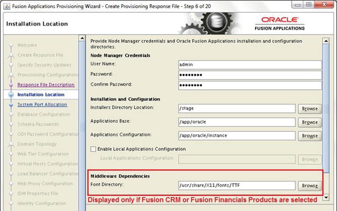
Figure 9-9. Installation Location details screen
The Installation Location details screen requires you to enter the following details about the installation.
Node Manager Credentials
1. Username and password: Enter any username and password for the Node Manager Administration role. These values will be used to configure the node manager and secure the WebLogic servers by using encrypted values. These same values will be used in keystore and wallet files.
Installation and Configuration
2. Installers directory location: Specify the location of the Fusion Applications Installation Repository where the installation media has been extracted, also referenced as REPOSITORY_LOCATION in earlier examples. In this case, the location is /stage. The wizard will check for a subdirectory named installers in this location. If no such directory is found, the installer will display an error.
3. Applications base: Specify a directory for the Applications base, which will act as the top-level directory for all Fusion Applications products. It is mandatory to specify a directory within a mount point instead of the mount point itself. For example, if /app is your mount point, you cannot specify /app. You must create a new directory within the mount point, for example /app/oracle. The installer user must also have permission to create this path in the parent directory. This path is also referred to as APPLICATIONS_BASE.
4. Applications configuration: This value will be populated automatically based on the value entered above. If this directory already has files in it, then the installer will throw an error suggesting that the directory be empty. The default value will be <APPLICATIONS_BASE>/instance. Leave this value unchanged.
5. Enable local Applications configuration: This checkbox is optional. This should be checked only if you want to store the configurations files locally instead of in a shared location.
Local Applications configuration: This field will be activated only if you have selected this checkbox. You need to specify a local directory on the host for this location. The wizard will copy the configuration files to this location. The directory must exist on a local disk and must be empty.
6. Middleware dependencies
Font Directory: This field will appear only if you have selected Oracle Fusion CRM or Oracle Fusion Financials related products. In all other cases, this field will not be displayed on this screen. Although the value is populated automatically, confirm it by checking the location manually and making sure that the TrueType fonts (TTF) and related files are present.
Linux x86-64: /usr/share/X11/fonts/TTF
Windows: C:WindowsFonts
Solaris/AIX: /usr/X11R6/lib/X11/fonts/TrueType
7. Oracle Business Intelligence repository password
RDP password: Enter a complex password to allow access to Oracle Business Intelligence Applications (OBIA) and Oracle Transactional Business Intelligence (OTBI) metadata repositories (RPD). Confirm it next.
Figure 9-10 shows the bottom portion of the screen, which was not visible in Figure 9-9.

Figure 9-10. Installation Location details screen (continued)
Once all these values are entered and manually verified, click Next to proceed to the System Port Allocation screen, as shown in Figure 9-11.

Figure 9-11. System Port Allocation screen
The screen requires you to input or verify the following ports. The default values are already populated. So if you do not have anything else running on the selected server or if you do not plan to use non-default ports, you can leave them unchanged. If you are provisioning for production or if your organization has non-default ports policy then you may change the value of the Applications base port.
As the screen suggests, the Fusion Applications provisioning internally allocates 4500 ports, and the ports are arranged in ascending order starting from the Applications base port. If you change the value of Applications base port from 7000 to 7000 + n then all subsequent Applications ports will change to <port number or range> + n as well. This does not apply to the node manager and IIR ports, which you can change independently. The default node manager port is 5556. This can be left unchanged unless you have another service running on the same port since the Node Manager port is not exposed to the users. Here is the list of ports requested on this page.
1. Applications base port: The default value is 7000. This is the starting port of the overall range of ports allocated for the Fusion Applications services. For example, if you have left this value to its default of 7000 then the CommonDomain Administration server port will be 7001 and the other ports will be set accordingly.
Other Ports
2. Node manager: The default value is 5556. The Node Manager is responsible for monitoring and controlling the status of the managed servers for every product domain hosted on the respective servers. Although the managed servers can be controlled independently of the Node Manager, for Fusion Applications provisioning, the node manager must always be running once it is configured in order to complete the provisioning phases.
3. Informatica Identity Resolution license server: The default value is 1601. This field will be available only if you have selected the Oracle Fusion CRM product offerings like sales, marketing, and so on. This specifies the port where the IIR License Server will be running.
Review the ports and click Next to continue to the Database Configuration screen, as shown in Figure 9-12.

Figure 9-12. Fusion Applications Transaction Database Configuration screen
The Database Configuration screen requires you to enter the following connection details of Fusion Applications Transaction Database including the SYSDBA privileged user (preferably SYS) credentials, single node or RAC hostname, service name/SID, and any port details. Once these details are entered, click Next to proceed to the Schema Passwords screen, as shown in Figure 9-13. The wizard will verify the connectivity to the database now and throw a warning if it cannot reach the database with the settings you entered. You can fix the issues and if you are sure that the values are correct but database is not running then you can opt to ignore the warning.

Figure 9-13. Database Schema Passwords screen
Tip
If you are unsure of some detail and want to resume the response file creation later, don’t cancel the wizard. Instead use the Save button to save the partial response file. This file must be completed before it can be used to provision an Applications environment.
The Database Schema Passwords screen requires you to select from two options. The selection is based on whether you specified the same or a different password for all schemas while running RCU for the Applications transaction database. You can refer to Figure 8-26 in Chapter 8 for more information.
Use the same password for all accounts: This is default option. If you selected the same password during RCU then select this option. You will be required to enter the single password for all schemas. This password must match the RCU password.
Use a different password for each account: If you selected different passwords for each schema while running RCU then you must enter each password individually here. There are two sections under this option. The first is for the Applications schemas and the second section is for middleware-related schemas (AS Common Schemas, SES, WebCenter, SOA, BI, and so on).
The wizard will validate the passwords and show a warning if it cannot validate. You can choose to ignore the warning if the database is not yet running. Click Next to proceed to ODI Password Configuration, as shown in Figure 9-14.

Figure 9-14. ODI Password Configuration screen
This screen requires you to enter an ODI supervisor password. Enter the same password that you selected for the supervisor password on the Custom Variables screen of RCU under the Master and Work Repository section. You can refer to Figure 8-27 in Chapter 8 for the Custom Variables screen. The wizard will validate this password as well. Once the password is entered, click Next to Proceed.
On the Topology Selection screen, you are required to select one of the three possible topology options, as shown in Figure 9-15. Of course at this point you already have your topology finalized so you can fill in these details. So far we have not yet started Fusion Applications provisioning, so you can increase the number of application nodes at this point. All you will need to do is to install Fusion Applications provisioning framework on other nodes.

Figure 9-15. Topology Selection screen (basic topology)
One host for all domains (basic topology): This is the default topology and also the selected topology for this example. In this case, all the Product WebLogic domains will be configured on same application host.
One host per domain (medium topology): We saw this topology in Chapter 2 as shown in Figure 2-8. Once you select this option you will be able to select a hostname for each of the domains being configured for the current configuration, as shown in Figure 9-16. In this example, since you have eight domains being configured, you can select up to eight different hosts for the application tier. You can select the same host for multiple domains as well. You will notice that the step title in left panel changes to Medium Topology when you select this option.

Figure 9-16. Topology Selection screen (medium topology)
O ne host per application and middleware component (advanced topology): Once you select this option the title of the step in the left panel changes to Advanced Topology. We saw one example of this topology in Chapter 2 as shown in Figure 2-7. Although the topology selection has only one selection radio for Advanced Topology, the actual configuration is done in further screens. Once you select Advanced Topology and click Next, the number of steps in the left panel increase from 20 to 20 + n where n is the number of WebLogic domains to be created for the selected configuration, as shown in Figure 9-17.

Figure 9-17. Topology selection (advanced topology)
Tip
Note that once you select Advanced Topology and click Next, you cannot change the topology later. The topology selection screen fields will become grayed out.
The Advanced Topology selection brings more screens in the wizard depending on the number of WebLogic domains being created. Figure 9-17 shows the example of CommonDomain where we need to select the host for the admin server and the managed servers. As you can see the list of ports is in ascending order depending on the Application base port selected earlier. Similarly you will see screens for all the product domains.
In this example, we have selected the basic topology with a single host called fahost for all domains, as shown in Figure 9-15. Click Next to continue to the Web Tier Configuration screen, as shown in Figure 9-18.
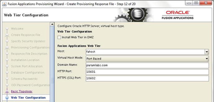
Figure 9-18. Web Tier Configuration screen
The Web Tier Configuration screen requires you to select the following properties for the Oracle HTTP server:
Web Tier Configuration
1. Install Web Tier in DMZ: Select this checkbox only if you have a DMZ (Demilitarized Zone) configured in your data center and you are allowing access to your applications to external sources. We discussed DMZ in the installation planning chapter.
Fusion Applications Web Tier
2. Host: Enter the name of the web tier host in your selected topology. Note that if you have selected DMZ then you must select a different hostname than any of the application tier hosts specified in the previous screens. In this case, we have selected two-tier topology so our web tier is hosted on the same server, called fahost.
3. Virtual Host Mode: We have to select from one of these three virtual host mode options.
IP Based: This is the default option. In this case, the product domain related URLs will be in selected Virtual IP:Port format. We will see this in the next screens.
Name Based: With this option we can map the product domain related URLs with distinct internal and external virtual names. This is more suitable for a production setup since from the URL we can distinguish the related product functionality.
Port Based: Use this option when you are not using a virtual hostname and want to distinguish the URLs as dedicated ports for each of the product families. In this case the HTTP server will be set up with aliases where each product-related port will be redirected to related product managed servers. In this example we have selected single host, so we’ll use this option.
4. Domain Name: Specify the default domain name of your infrastructure. This domain name will receive the Fusion Applications related requests. You will see the same domain name populated automatically in subsequent screens, where any name-based references are used.
5. HTTP Port: Depending on the topology selected in the previous screen, the value of default HTTP port will be automatically populated.
6. HTTPS (SSL) Port: Depending on the topology selected in previous screen, the value of default HTTPS port will also be automatically populated.
7. SMTP Server: SMPT Server related options will be displayed only if you have selected Oracle CRM Configuration as outbound emails are required for email marketing products. Specify the Outgoing Mail Server (SMTP) hostname or IP address. Make sure that the SMTP hostname resolves from DNS or a local hosts file. You also need to specify the outgoing mail server port. The default value for this port is 25.
The next screen will vary depending on the virtual host mode selected in this screen. We will look at the next screen with these virtual host mode selections.
Figure 9-19 shows the Virtual Hosts Configuration screen for port-based virtual host mode. As you can see for each product domain, you can select internal and external ports. For example, the internal URLs related to CommonDomain start with http://fahost.paramlabs.com:10633 and the external URLs will be https://fahost.paramlabs.com:10634 . Although you can change the values of these ports, it is advisable to change them through the Applications base port only to avoid any port conflict or overlap. The Virtual Hosts Configuration screen will look as shown in Figure 9-20 if you select name-based virtual host mode for the web tier.

Figure 9-19. Virtual Hosts Configuration screen (port-based virtual host mode)

Figure 9-20. Virtual Hosts Configuration screen (name-based virtual host mode)
Here you will not specify any ports but virtual hostnames for each product family. You can specify different virtual hostnames for internal and external URLs. The prerequisite for this is to have each of these names registered in your organization DNS server so that the URLs will resolve from servers as well the user’s network. Now we will see the same screen with IP-based virtual host mode selected for web tier, as shown in Figure 9-21.

Figure 9-21. Virtual Hosts Configuration screen (IP based virtual host mode)
Although the screen initially displays the same hostname as web tier host for all internal and external ports, you can change these internal and external virtual names individually. Here also if you are using a virtual name other than the hostname, you must make sure that these names are registered in the DNS mapped to the server’s IP address. You can also specify one virtual name for all internal applications and one virtual name for external URLs. Make sure to document these ports since you may need to configure the network firewall accordingly if you are not planning to use the load balancer in your environment. If you do not change the virtual hostnames for the Application domains, the configuration remains similar to the port-based virtual host mode. However, note that the range of ports is different for IP-based and port-based virtual hosts configuration.
Review and modify the Virtual Hosts Configuration screen and click Next to proceed to the Load Balancer Configuration screen, as shown in Figure 9-22.

Figure 9-22. Load Balancer Configuration screen
The Load Balancer Configuration screen allows you to select internal and external load balancer virtual hostnames and port details for your Fusion Applications environment.
Although the role of the load balancer is to provide a single point of entry for an environment with multiple hosts for same service, you can also use the load balancer for non-high available environments. Having a load balancer VIP and port simplifies the firewall configuration by reducing the number of ports required to be opened from the user network to Fusion Applications infrastructure. This also allows you to use simple to remember virtual hostnames.
Although you may use common hardware network load balancers in your organization, you may need to allocate different NLB (Network Load Balancer) IP addresses to resolve each internal and external VIP host. The load balancer should be configured to forward the traffic to internal servers on domain-specific ports. You will need to work closely with your network security team in order to configure this seamlessly.
Modern Network Firewalls like F5 BIG-IP and a few other appliances that provide load balancing features for multiple URLs on single source IP as well. These appliances can forward the traffic to servers based on incoming URL requests using preconfigured rules.
The load balancer configurations screen requires the following details to be entered.
1. Load Balancing Enabled: All the remaining options on the screen remain grayed out until this checkbox is selected. If you are not planning to use network load balancer in your environment then you can leave this checkbox unselected. In this example we are not selecting this checkbox. If you select this checkbox, you must enter all the following values including the internal and external VIPs.
2. Internal Load Balancer for Fusion Applications: You will be required to enter the following values for each product domain even if they are not configured. The required values will be configured during the provisioning.
Internal VIP Host: Specify a name for an internal VIP host for the specified product. This name must be configured in an internal DNS.
Internal VIP Port: Specify the port for internal URLs. The default value is 80.
3. External Load Balancer for Fusion Applications: Similar to internal load balancer, you must also enter following values for each product domain. You may specify the same or different values for external VIPs.
External VIP Host: Specify a name for external VIP host for specified product. This name must be configured in external DNS.
External VIP Port: Specify the port for external URLs. The default value is 443.
Once the appropriate values for load balancer are selected, click Next to proceed to the Web Proxy Configuration screen, as shown in Figure 9-23.

Figure 9-23. Web Proxy Configuration screen
The Web Proxy Configuration is an optional selection. This should be enabled only if you have any integration with external applications outside your organization through the Internet. Since servers in data centers generally do not have direct Internet access, you must route the Internet traffic through your corporate web proxy. Figure 9-23 shows an example web proxy configuration for Fusion Applications environment. Let’s look at the possible configurations on this screen.
1. Enable Web Proxy: If you do not want to enable Internet access from the hosts then you can just leave this checkbox unselected and the rest of the screen will remain grayed out. Once you select this checkbox, the following fields will be enabled.
a. Web Proxy Host: Enter the name of your corporate web proxy server.
b. Web Proxy Port: Enter the port on which the proxy server is configured. You must make sure that the firewall rule for allowing the access to the required proxy server ports from the Fusion Applications nodes is configured and enabled.
2. Enable Secure Web Proxy: This checkbox is enabled only if the Web Proxy checkbox is already selected. It is advisable to use Secure Web Proxy to SSL enable the Internet traffic. Once you select the Secure Web Proxy checkbox, the following fields also become active and mandatory.
a. Secure Web Proxy Host: Enter the name of SSL host to provide secure proxy.
b. Secure Web Proxy Port: Enter the configured SSL port for secure proxy.
c. No Proxy for Hosts: This option will allow you to skip web proxy for any hosts included in this list separated by vertical bar ( | ). By default, all hosts in the same domain are excluded from the proxy.
3. Proxy Server Requires Authentication: Most proxy servers require authentication with a domain username and password. If your organization proxy server requires authentication then select this checkbox and provide the following value.
a. User Name: Enter the username of the person allowed to access the proxy server.
b. Password: Enter the password for this username.
Enter the appropriate values and click Next to proceed to another important screen of loading the IDM properties file, as shown in Figure 9-24.

Figure 9-24. The IDM Properties File screen
The IDM Properties File screen was introduced in Fusion Applications 11g, Release 5 (11.1.5). Until this release, we were required to enter all parameters related to the Oracle Identity and Access Management manually in the subsequent screens. Due to a large number of parameters required for Identity Management, the process was prone to errors. Oracle had greatly reduced the chances of error in Identity Management related details by introducing the idmsetup.properties file, which contains most of the variables and values required in the subsequent screens.
Now let’s refer back to the Identity Management provisioning and you may notice that at the end of Identity Management provisioning the wizard created an IDM properties file named idmsetup.properties under the Identity Management shared configuration directory. The location of the file on Identity Management node is <IDM_CONFIG_DIR>/fa/idmsetup.properties. This file includes all the required details of the Identity Management installation, which can be directly used for populating the required values in the next two screens. If you do not have this file, you can still choose to enter the required values manually in the next screens.
Before we can select the file in the wizard, we must copy the idmsetup.properties file from the IDM node to any desired location on the current node.
[fusion@fahost bin]$ cd /app/fusion/
[fusion@fahost fusion]$ scp fusion@idmhost:/app/oracle/config/fa/idmsetup.properties.
Now the file should be available at /app/fusion/idmsetup.properties on the primordial host as well. Select Load IDM Configuration from IDM Properties File. You can enter the path manually in the textbox for IDM Properties file or browse for this file as shown in Figure 9-24. If you want to enter the values in subsequent screens, then select the Do Not Load IDM Configuration from IDM Properties File option.
Once you have entered the IDM properties filename, press the Tab key to populate the contents of the idmsetup.properties file in the text area titled IDM Properties File Contents. This textbox is read-only and cannot be modified.
Click Next once the appropriate values are selected. Regardless of whether you have selected the IDM properties file, you will see the warning prompt shown in Figure 9-25 informing you that once you confirm you cannot change the choices in this screen.

Figure 9-25. Confirmation prompt for loading the IDM properties
Click Continue to proceed to the Identity Configuration screen, as shown in Figure 9-26.

Figure 9-26. Identity Management Configuration screen
Tip
Despite entering the values in the screen, as shown in Figure 9-24, sometimes you may see a red error symbol in the left panel against the current step. You may safely ignore it at this point since this is a known issue with this wizard. Due to this warning prompt, it displays an error symbol and does not clear it despite confirming the message box.
If you are creating a provisioning response file for Fusion Applications versions earlier than 11.1.5 or if you have selected Do Not Load IDM Configuration from IDM Properties File, then you may need to manually enter all the values in this screen. In all other cases, you will see most of the values already populated in this screen. Let’s have a look at the details required to be entered in this screen. Be very careful to verify details in this as well as the next screens since these values determine the integration of Fusion Applications with Identity Management.
Identity Management Configuration
1. Super User Name: Specify the name of the Fusion Applications super user who will be created and granted administrator and functional setup privileges. In earlier versions of Fusion Applications, we were required to enter any desired super user name here and the default value was weblogic_fa. From recent versions of Fusion Applications the wizard provides the FAAdmin as the default name. You can specify any existing user as well, which can be granted these privileges. We will leave this as FAAdmin.
2. Create Administrators Group: Specify whether you want to create an administrators group in OID. Members of this group have special administrative privileges on all middleware components. If you already created this group in OID then you can deselect this checkbox. Otherwise, it must be selected.
3. Create Monitors Group: Specify whether you want to create a monitors group in OID. Members of this group have read-only access to the Oracle WebLogic server console for all domains. If you have already created this group in OID then you can deselect this checkbox. Otherwise, it must be selected.
4. Create Operators Group: Specify whether you want to create an operators group in OID. Members of this group can view the WebLogic server configuration except encrypted attributes. These users can also start/stop/resume the WebLogic server but cannot alter any configuration. If you have already created this group in OID then you can deselect this checkbox. Otherwise, this must be selected.
5. Identity Store Server Type: OID and OVD both are supported as the identity store server. Select Oracle Identity Directory or Oracle Virtual Directory here. The default value is already populated if you have selected the idmsetup.properties file in an earlier screen.
6. Use SSL to communicate with the Identity Store: This field is grayed out since currently it is not supported and is a placeholder for future releases only.
7. Identity Store Host: The value is already populated based on your Identity Management configuration file. If you have not specified the Identity Management properties file earlier then enter the identity store hostname here. For example, idmhost.paramlabs.com. Leave this value unchanged.
8. Identity Store Port: The Identity Store Port value is already populated in this example. The default value is 3060. Leave this unchanged.
9. Identity Store Secure Port: Although Identity Store Secure Port value is already selected, it is currently not supported for the Fusion Applications environment. This field remains grayed out.
10. Identity Store User DN: The Distinguished Name (DN) of the user with read/write access to the identity store is already selected based on the Identity Management environment properties file. For example, cn=IDRWUser,cn=Users,dc=paramlabs,dc=com.
11. Identity Store Password: All password fields in this screen are blank since idmsetup.properties file is a plain-text file. The passwords are not stored in that for security reasons. Enter the password for the user in this field.
12. Identity Store Read-Only User DN: The Distinguished Name (DN) of the user with read-only access to the identity store is already selected based on our Identity Management environment properties file. For example, cn=IDROUser,cn=Users,dc=paramlabs,dc=com.
13. Identity Store Read-Only Password: This field is also blank and the password for the user must be entered here. Since we do not have confirm password fields here, be careful to enter the password correctly.
14. Identity Store User Name Attribute: The choice of values in this field are uid (user ID) or cn (Common Name). The populated value is uid based on your configuration. Leave this unchanged since it must match your environment.
Figure 9-27 shows the bottom section in continuation of the same screen.
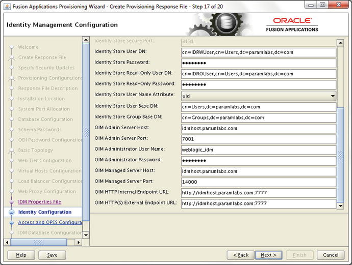
Figure 9-27. Identity Management Details screen (continued)
Enter the following values in this section of the Identity Configuration screen.
15. Identity Store User Base DN: Mention the Distinguished Name (DN), which will serve as a root node for loading all application users data. Leave it unchanged if the default value is already selected based on our environment. For example, cn=Users,dc=paramlabs,dc=com.
16. Identity Store Group Base DN: Mention the Distinguished Name (DN) which will serve as root node for loading all group data. Leave it unchanged if default value is already selected based on our environment. For example, cn=Groups,dc=paramlabs,dc=com.
17. OIM Admin Server Host: Enter the value of the Identity Management domain administration server host. For example, idmhost.paramlabs.com. Leave it unchanged if it’s already populated.
18. OIM Admin Server Port: Enter the Identity Management Administration Server port value here. The default value 7001 should be filled here if the Identity Management properties file was selected.
19. OIM Administrator User Name: Enter the name of the Identity Management WebLogic administrator user here. If you used the Identity Management provisioning framework earlier, the default value of Administration username would be weblogic_idm and already populated here. Do not confuse this with the OIM privileged user xelsysadm since this field requires the domain administrator username weblogic_idm here.
20. OIM Administrator Password: As mentioned earlier, all password fields are not filled automatically and no confirm password fields are available. Type the password for the OIM administration user.
21. OIM Managed Server Host: Depending on the topology selected, the value of OIM managed server host could be same as OIM admin server host or different. This value is already populated based on your IDM properties file. In our case since we used single host for all Identity Management middleware components, the default value is idmhost.paramlabs.com.
22. OIM Managed Server Port: The default value for OIM Managed server Port is 14000 if you have used IDM Provisioning Framework for Identity Management installation. Although the OIM related URLs show common HTTP Port but internally it redirects to 14000 port only. So you must enter the port where OIM Server is listening. Leave this unchanged if already populated.
23. OIM HTTP Internal Endpoint URL: This URL is used for all communication between Oracle Fusion Applications and the Oracle Identity Manager. This value should be based on internal access point of Identity Management HTTP server. By default this value is in http://<IMD Web Host>:<web port> format. The hostname and port values should be either of the web host or the load balancer if you have configured one. For example http://idmhost.paramlabs.com:7777
24. OIM HTTP(S) External Endpoint URL: Enter the secure URL for Oracle Identity Management HTTP server. This is generally used to access Identity Management from browser or external sources. By default the value should be HTTPS format but if you have not set up the HTTPS endpoint then you can enter HTTP value as well. Note that the communication will remain non-secure. If you have configured an external HTTPS load balancer URL then you must enter it here. In this example, we have not used an external HTTPS URL so we have entered the same as above for demo purposes.
Tip
In general if you have loaded the IDM properties file in the previous step, you need to only select the three checkboxes for creating the administrators, monitors, and operators groups and enter all the required passwords. The rest of the values should be left unchanged in most cases.
Note that the wizard will verify the URLs and port accessibility and if any of these are not reachable then it will display warning message on the screen as well as the bottom panel. You can either choose to fix the errors and if you believe the information entered is correct but the Identity Management environment is not running at the moment then you can skip the warning as well. Note that you must make sure that all Identity Management components as well as Fusion Applications transaction database are running before proceeding to the actual provisioning process.
Once the required values are entered and verified, click Next to proceed to the Oracle Access Manager Configuration, as shown in Figure 9-28.

Figure 9-28. Access Manager and Platform Security Services Configuration
Similar to the Identity Configuration screen, in Access Manager and OPSS Configuration screen, the values are already populated if you have loaded the IDM properties earlier. If you are creating a provisioning response file for Fusion Applications versions earlier than 11.1.5, you may also need to manually enter all the values in this screen. The following are the list of values to be entered in this screen.
Oracle Access Manager Configuration Parameters
1. OAM Admin Server Host: Enter the name of the host where the Administration Server for Oracle Access Manager is configured. Regardless of the topology selected, the admin server host for OIM and OAM will be the same. This value could be either the physical hostname or VIP name. In this case since we have loaded the IDM Properties file, the value is already populated. For example, idmhost.paramlabs.com.
2. OAM Admin Server Port: Enter the value of the OAM administration server port. This value will generally be same as the value entered earlier for OIM Admin Server Port. In this example the value has been pre-filled with 7001.
3. OAM Administrator User Name: This filed can be confusing since we entered domain administrator username for OIM administrator user while for OAM administrator user we need to enter the name of the user which has been granted OAM Administrator privileges while provisioning Identity Management. If you have used Identity Management provisioning framework then this value defaults to oamadmin. In this case the value has already been populated, so leave it unchanged.
4. OAM Administrator Password: Enter the password that you selected for the oamadmin user.
5. OAM AAA Server Host: Enter the hostname of the OAM proxy server which is configured with the OAM managed server. This is generally the name of the host where the OAM component has been installed and configured based on the topology selected. Since in this example we have used single host for all Identity Management components, the value remains the same—idmhost.paramlabs.com.
6. OAM AAA Server Port: Enter the value of OAM proxy server port used for communication with WebGate. If you have provisioned Identity Management using IDM framework then this value defaults to 5575. Note that this value is not same as the port that OAM Managed Server listens to (14100) so you must leave this value unchanged if it is already populated.
7. Access Server Identifier: Enter the name of Oracle Access Server Managed Server which is also called Access Server ID. For Identity Management environment created using Identity Management Provisioning Framework this value defaults to wls_oam1.
8. Enable Second Primary Oracle Access Manager: If you have configured second primary instance of OAM then you should select this checkbox. Once this checkbox is selected, the next text field for Second Access Server Identifier becomes active and mandatory.
Second Access Server Identifier: Enter the second Access Server ID here. Since in our case second Primary OAM Server is not configured, the checkbox is deselected and this field remains grayed out.
9. WebGate Password: The WebGate password must be entered since this field is empty by default. Specify a complex password for WebGate resource.
10. Confirm WebGate Password: Retype the password.
Figure 9-29 shows the bottom section of the same screen.

Figure 9-29. Access manager and platform security services configuration (continued)
Enter the following values related to the Oracle Platform Security Services and Identity Management Keystore Configuration sections. If you have loaded the IDM properties file earlier, then in most cases you only need to enter the required passwords without changing other values.
Oracle Platform Security Services Configuration Parameters
11. Default to identity store: If you want your policy store to be same as your identity store then you can select this checkbox Note that at the moment the only supported directory for policy store is OID so if you have selected Oracle virtual directory for your identity store earlier then you must not select this checkbox and provide OID details for the policy store. When you select this checkbox, three fields will be automatically populated based on the values selected for identity store, namely OPSS Policy Store Host, OPSS Policy Store Port, and OPSS Policy Store Secure Port (currently disabled). In our case we can select this checkbox but the required values have been populated already based on IDM property file. So we will leave this untouched.
12. Use SSL to communicate with OPSS Policy Store: This option is not yet supported in the current release so it remains grayed out. This is a placeholder for future releases.
13. OPSS Policy Store Host: If you have selected the previous checkbox or loaded IDM properties file earlier then this and related port values will be filled automatically. If you are having ID Store in OVD and policy store in OID then be sure to enter the appropriate hostname. The value based on the selected topology is the same as the ID store host. For example, idmhost.paramlabs.com.
14. OPSS Policy Store Port: The default value for this field is 3060, which is same as the ID store port. Or else enter the policy store port or load balancer port value.
15. OPSS Policy Store Secure Port: Although this parameter is not yet supported as of the current release, the secure port value is automatically loaded from the IDM properties file.
16. OPSS Policy Store Read-Write User Name DN: Even if you have selected the same OID for identity store and policy store, you must enter different value for Oracle Platform Security Services Policy Store. Enter the Distinguished Name (DN) for the user to have read/write access to the OPSS policy store. If you have used IDM provisioning framework then the value defaults to your domain specific value similar to cn=PolicyRWUSer,dc=paramlabs,dc=com. Leave this value unchanged.
17. OPSS Policy Store Password: Enter the password selected for the OPSS policy store user mentioned above.
18. OPSS Policy Store JPS root Node: In older releases JPS root node for Fusion Applications (POLICYSTORE_CONTAINER) was created as cn=jsproot while from Fusion Applications 11g, Release 7 onward the value is created as cn=FAPolicies. Leave this unchanged if it’s already populated based on your IDM properties file.
19. Create OPSS Policy Store JPS root node: For some releases the IDM provisioning framework creates the OPSS Policy Store JPS root node. So check if the above already exists in OID then you must deselect this checkbox. Note that depending on the release you are provisioning, this might not already exist. Confirm the existence of JPS root node before selecting or deselecting this checkbox; otherwise, you may receive an error during provisioning suggesting that the JPS root node already exists.
Identity Management Keystore Configuration Parameters
The fields in this section are enabled only if you have enabled SSL for identity store, policy store, or OIM endpoint. In other cases the complete section remains grayed out.
20. IDM Keystore File: The location of Java keystore file for IDM, which contains the certificate files for Identity Management components. If you have selected SSL then the value will be automatically filled based on the IDM properties file.
21. IDM Keystore Password: You must enter the same password that you have configured for IDM keystore file.
Verify the details on the screen even if they are automatically populated from the properties file, enter the passwords, and click Next to proceed to IDM Database Configuration screen, as shown in Figure 9-30.

Figure 9-30. Identity Management Database Details screen
In the IDM Database Configuration screen as shown in Figure 9-30, you are required to enter the Identity Management database connection details, including single node or RAC hostname, port, and the service name of the Identity Management database (idmdb in this example).
You also need to specify credentials for MDS data schema in this screen. We had already created MDS data schema for Oracle Web Services Policy Manager during Identity Management RCU. Provide the same details as you provided during RCU in the following fields. Once the database details are entered, click Next to proceed to the Summary screen, as shown in Figure 9-31.

Figure 9-31. Response file creation summary
The main summary section shows all the details you entered throughout all screens in plain text format. Although the actual provisioning response file contains a parameter-value format instead of the text, the summary text gives a clear view of the values selected so far.
The summary screen has the following sections. I strongly recommend you go through the summary as you can easily notice any incorrect information in this consolidated view.
Summary: The Fusion Applications Response File creation summary includes a plain text summary of all parameters entered in previous screen. This is a large scrollable read-only text area.
Provisioning Response File Name: Enter the name of the response file to be created. Note that this is the physical filename and should not be confused with the response file name provided in Figure 9-8. The default value is provisioning.rsp. You can change the name of this file if you are creating and storing multiple response files in same location.
Provisioning Summary File Name: Enter the name of the file that will store the summary information in plain text. This file is directly not used by the provisioning process but is useful for reading any parameter directly instead of running through the wizard.
Directory: The location where these two files will be created. By default it is the same directory from where the provisioning script has been executed. For example, /app/fusion/provisioning/bin. We can leave this value unchanged.
Review the summary and the required filenames. Click Finish to complete the response file creation and to close the window. I recommend you to make a backup of the response file and the summary file to safeguard against accidental modification of these files.
[fusion@fahost fusion]$ cd /app/fusion/provisioning/bin/
[fusion@fahost bin]$ cp -pr provisioning.rsp provisioning.rsp.bak
[fusion@fahost bin]$ cp -pr provisioning.summary provisioning.summary.bak
Update an Existing Provisioning Response File
It is quite possible that while creating the provisioning response file you may have tentative details only but you may still want to create the file with the current information and update it later once you have finalized the complete environment details. Even if you have partially created the response file by saving the contents mid-way, you must also complete the response file creation before you can use it to provision an applications environment.
Let’s look quickly at the procedure to update an existing provisioning response file. The command to invoke the wizard remains the same except the option which we will select in order to update the response file. Set JAVA_HOME before starting the wizard to the location where we installed JDK.
[fusion@fahost ∼]$ export JAVA_HOME=/app/fusion/jdk6
Let’s launch the Provisioning wizard now from <framework_location/provisioning/bin as follows. After the Welcome screen, the next screen will provide same six provisioning options as shown in Figure 9-32.

Figure 9-32. Update Response File option in the Provisioning wizard
[fusion@fahost ∼]$ cd /app/fusion/provisioning/bin
[fusion@fahost bin]$ ./provisioningWizard.sh &
Note
As of the current release it is not possible to add or delete product offerings from the existing response file. You must create a new response file in order to do so.
In this case we will select option 4 (for Fusion Applications release 9 and above) or option 3 (for Fusion Applications release 8 and earlier) which is Update an Existing Provisioning Response File. Additionally, the wizard will require you to enter the full path of the existing response file (complete or partially completed Response File) which you would like to update. You can use the Browse button to locate the file.
Once the response file details are entered, click Next to continue with the wizard. Note that the wizard will be very similar to the wizard for creating a new response file except a few differences which we will see now. It is interesting to see that the Update Response File option does not allow us to modify the product configuration selected for provisioning. Therefore the Provisioning Configuration screen remains grayed out, as shown in Figure 9-33.

Figure 9-33. Grayed out Provisioning Configuration window
In this screen you can only see the list of WebLogic domains and managed servers to be created using the Details option. The reason behind not allowing changes in this screen is that if you change any values in this screen then the further screens which have already been populated with WebLogic domains, topology, and ports details must be modified and they may require a complete rework in terms of responses and may hamper the vary purpose of updating the response file. Review the information on this screen and click Next to proceed to the Response File Description screen, as shown in Figure 9-34.

Figure 9-34. Updating Response File Description
The next screen will show the response file description and version as you entered while creating the response file. The Created By and Created Date fields remain the same as the original file and do not get updated even if you update the response file. Make sure to update the response file version number manually for tracking purposes. You may also want to edit the response file description to mention the major changes being done in this response file. Since all the other steps are similar to creating a new response file, we will not discuss them here.
This concludes all the preparation tasks for provisioning a new Fusion Applications environment. Let’s quickly look at the additional option provided in Fusion Applications Provisioning wizard in the recent release before completion of this chapter.
Creating a New Response File for Extending an Existing Environment
This option has been introduced from Fusion Applications 11g, Release 9 (11.1.9) onward only and was not available in earlier releases. This option allows you to add new products in your already provisioned existing Fusion Applications environment. These products can either be newly introduced in the new release or existing products from earlier releases which you did not provision earlier and are available as part of new release as well. Since this option is not related to Fusion Applications installation but is only for the upgrade process, I will only give you an introduction to this option here.
Before proceeding with this option you must have an existing Fusion Applications environment running and a complete backup must have been taken. Once you create a new response file for upgrade, you need to provision the new products similar to normal provisioning process. Once the provisioning completes, you must follow the normal upgrade orchestration process.
The step to invoke the wizard is precisely the same since we will run the same Provisioning wizard here as well and select the appropriate option. Launch the Provisioning wizard as we saw earlier.
Select the option called Create a Response File for Extending an Existing Fusion Applications Environment, as shown in Figure 9-35 and then click Next. The subsequent screens will provide you the details of the existing products provisioned in your environment. You’ll also see the Configuration selection screen, which will allow you to select additional products that are not already provisioned. The number of WebLogic servers and domains will change accordingly. The subsequent screens will have most fields grayed out except the details for newly configured product domains, ports, and so on. We will skip the discussion of this since it is not related to installation of a new Fusion Applications environment. Once such a response file is created, you can proceed to provisioning the environment followed by the upgrade process.

Figure 9-35. Selecting the option to create a response file for extending existing environment
Summary
This chapter mainly dealt with preparing for the actual provisioning of Fusion Applications environment. However the response file creation steps should have provided you with a good overview of the components and topology of Fusion Applications environment and explained how they interact with Identity Management components. Creating a correct provisioning response file is of utmost importance in the Fusion Applications provisioning process since the installation of Fusion Applications environment will solely use the response file to perform a seamless installation without prompting for any further details.
In the beginning of this chapter you saw the directory structure of the provisioning framework, which will also help you in the upcoming chapters, since the provisioning process uses the framework extensively for fully automated orchestration of the provisioning phases. You also saw how to update an existing provisioning response file followed by a quick overview of creation of a new response file for extending an existing Fusion Applications environment. Now you will proceed to the final phase of Fusion Applications installation, which is the provisioning of the Fusion Applications nodes.