1.6. PIC16 Program and Debug
• Programming the chip
• In-circuit debugging
• Design package
Once the compiler has produced the hex file, it can be downloaded to the target application board. However, it is generally preferable to test it first by software simulation. This means running the program in a virtual MCU to test its logical function. This can be done within MPLAB (tabular output) or using a third party debugging tool such as Proteus VSM (graphical output). More details on simulation are provided in Appendix C, and VSM interactive simulation is referred to throughout the text to provide circuit schematics and debugging facilities.
Programming
A low-cost programmer available at the time of writing is the Microchip PICkit2 programmer (Figure 1.17). This connects to the USB port of the host PC, with the programming module plugging direct into the target PCB. The six-way in-circuit serial programming (ICSP) connector, between the programmer module and the target board, must be designed into the application circuit. An in-line row of pins provides the programmer connection to the target MCU, as shown in Figure 1.18.
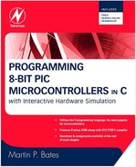
Figure 1.17. PICkit2 Demo System Hardware (reproduced by permission of Microchip Inc.)

Figure 1.18. ICSP Target Board Connections
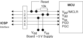
Pin 1 carries the programming voltage (12–14 V) and is connected to pin Vpp, which doubles as the MCU reset input, !MCLR. Pin 4 (PGD) carries the program data and pin 5 (PGC), the program clock. Any other circuits connected to these pins must be designed with care, so that they do not interfere with the programmer. The USB output provides the target board power, up to a limit of 500 mA, on pins 2 and 3. If necessary, a separate target board supply must be provided.
Once the hardware is connected up and the programmer drivers loaded, the programming utility window (Figure 1.19) can be opened by running PICkit2.exe file, selected from the Programmer menu. The hex file created by the compiler is imported via the file menu and downloaded using the write button. The target program is run by checking the On box.
Figure 1.19. PICkit2 Programmer Dialog

Debugging
If in-circuit debugging is required, the Microchip MPLAB ICD2® in-circuit debugger (Figure 1.20 and 1.21) is recommended. This allows the application program to be tested in real hardware by using the same MPLAB debugging tools used in the simulation mode: source code display, run, stop, step, reset, breakpoints, and variable watch windows. The target system needs its own power supply and an ICD connector.
Figure 1.20. Microchip ICD2 Module

Figure 1.21. ICD2 Program and Debug System

With power supplied to the target, load the application project files. Select Debugger, Select Tool, MPLAB ICD2. The debug control panel appears with controls to run, step, and reset (Figure 1.22). If the program is recomplied after a change in the source code, the target can be automatically reprogrammed.
Figure 1.22. ICD Debugging Windows

Use of breakpoints is generally the most useful debugging technique in C, as it allows complete blocks of assembler to be executed at full speed. These are enabled by right clicking on the source code and indicated by a red marker. Once set, they can be temporarily enabled and disabled. The watch window, selected from the View menu, allows program variable values to be monitored as the program progresses.
When debugging has been completed, the chip must be reprogrammed for the final time by selecting Programmer, Select Tool, MPLAB ICD2. Then, hit the Program Target Device button. When done, the program can be stopped and started using the Hold In Reset and Release From Reset buttons. When the ICD pod is disconnected, the program should auto-run in the target system.
Design Package
The components of the ECAD design package used in this book are listed below. The PCB implementation tools are not described further, as they are outside the scope of this programming guide.
• Circuit schematic capture (Proteus ISIS)
• Interactive circuit simulation (Proteus VSM)
• PCB layout design (Proteus ARES)
• PIC development system (Microchip MPLAB)
• PIC C Compiler (Custom Computer Services CCS C)
• PIC programming and in-circuit testing (Microchip ICD2)
Assessment 1
5 points each, total 100
1. List five consumer products that typically include a microcontroller.
2. Identify the five functional elements of a microcontroller.
3. Explain why flash ROM is an important technology in microcontrollers.
4. State five important characteristics of a microcontroller that should be considered when selecting the best part for a given application.
5. Describe briefly the process of program execution in a microcontroller, referring to the role of the program memory, instruction register, program counter, file registers, and working register.
6. State the function of the following registers in the PIC16F877: 02h, 03h, 09h, 89h, 20h.
7. Explain the significance of the following abbreviations in relation to the configuration of the PIC microcontroller: RC, XT, WDT, PUT, NOWRT.
8. Explain the function of the following elements of the PIC I/O circuit: tristate gate, current driver, data direction latch, input data latch, output data latch.
9. A 16-bit PIC hardware timer is driven from the internal clock signal, and the MCU is operating with a 20-MHz crystal. Calculate the preload value required to produce an interrupt every 10 ms.
10. If an analog-to-digital converter has a positive input reference voltage of 2.048 V and is set up as for 8-bit conversion, calculate the resolution of the ADC in millivolts per bit and the output code if the input voltage is 1.000 V.
11. Refer to Figure 1.9, and briefly explain the timer interrupt process and why it is useful.
12. Sketch the RS232 signal that transmits the character X (ASCII code 01011000) on a line operating at ±12 V. Indicate the stop and start bits as S and P.
13. Explain the difference between an asynchronous and synchronous data transmission by reference to RS232 and SPI.
14. Explain the difference between hardware and software addressing as used by SPI and I2C.
15. Explain briefly why SPI is generally faster than I2C.
16. A page of plain text contains about 1000 ASCII characters. Estimate the minimum time required to transmit this page over a 9600-baud RS232 link and an SPI line, under the control of an MCU running at 20 MHz, stating any assumptions made.
17. State the function of each of the C project files that have the following extension: C, HEX, COF, LST, and ERR.
18. State the function of the five connections in the PIC in-circuit programming and debugging interface.
19. Study the content of the dissembler window in Figure 1.22, and state the function of the five visible windows.
20. List a minimum set of development system hardware and software components required to create a C application for the PIC microcontroller.
Assignments 1
Assignment 1.1
Download the data book for the PIC16F87X MCUs from www.microchip.com. Study Figure 1.2, the PIC16F877 block diagram. Describe in detail the sequence of events that occurs when the data code for 25510 (111111112) from a machine code instruction is output to Port D. Refer to the role of the program memory, program counter, instruction register, instruction decoder, file register addressing, internal data bus, and clock. What path must the data follow to get from the program memory to Port C? Describe the setup required in Port C to enable the data byte to be observed on the port pins (Figure 1.4). Refer, if necessary, to PIC Microcontrollers: An Introduction to Microelectronics by the author.
Assignment 1.2
Research a list of SPI and I2C peripherals that might be useful in constructing PIC applications. Identify typical memory, interfacing, and sensor chips that use these interfaces and summarize the range of devices available for each interface.
Assignment 1.3
Download and install MPLAB development system from www.microchip.com, and the demo C complier for the PIC16F877 from www.ccsinfo.com. Create the project OUTBYTE as described in Section 1.5. Enter the source code and save in the project folder. Copy the header file into the same folder. Compile the program and view the files created in the folder. Check that the .hex, .lst, and .cof files have been created. Test the program in simulation mode; arrange the MPLAB windows as seen in Figure 1.6 and check that Port C is loaded with the output byte FFh. Study the assembler version of the program; note the number of instructions required to implement the C output statement. Reset and step through the program, noting the two phases: initialization and loop. Change the output number in the source code from 255 to 8510, recompile, and run. What is the Port D output now in binary and hex?