
4.5. PICDEM Analog Sensors
• Light switch application
• Temperature display application
The mechatronics board is fitted with a light and temperature sensor, each of which produces an analog output in the range of 0–5 V. In common with many sensors now available, a signal conditioning amplifier is built in, so that no additional components are needed to interface with an MCU.
Light Sensor
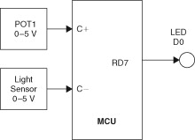
The light sensor can be tested using the analog comparator inputs of the 16F917, which allow two input voltages to be compared. An output bit in a status register is set if the positive input (C+) is at a higher voltage than the negative input (C−) or a reference voltage. A range of setup options are defined in the header file.
The block diagram in Figure 4.11 shows the hardware configuration for this test. The connector pin LIGHT, the light sensor output, is connected to RA0 (comparator input C−) and POT1 to RA3 (comparator input C+), with LED D7 is assigned to RD7 to display the comparator state. When the light level is reduced, the output switches on. Conversely, it goes off as the light is increased through the switching level, which is adjustable using POT1. This simulates the operation of an automatic streetlight switch or security lamp. The program LIGHTCON is outlined in Listing 4.12 and the source code shown in Listing 4.13.
Listing 4.12. Outline of Light Sensor Test Program
LIGHTCON
Select MCU 16F917
Initialize comparator input
Main loop
If light>set level, switch output OFF
Else switch output ON
Listing 4.13. Light Switch
///////////////////////////////////////////////////////////////////////
// LIGHTCON.C
// Auto light switch uses comparator inputs on mechatronics board
// Pot 1 adjusted for light switching level.
// Connect: LIGHT to C1−, POT1 to C1+
///////////////////////////////////////////////////////////////////////
#include “16F917.h”
void main()
{
setup_comparator(A0_A3_A1_A2); //Setup for PICDEM board
while(1)
{if(!C1OUT) output_low(PIN_D7); //Switch off LED if light>pot
else output_high(PIN_D7); //Switch on LED if light<pot
}
}
Figure 4.11. Comparator Test Setup
As we see, in the program, only the setup function is needed, which assigns the comparator inputs to Port A pins. Two comparators are available, and the setup used here is the same for all comparator applications using this hardware. C1OUT is the bit label assigned to the Comparator 1 output bit, which is tested using the ifstatement. The LED output is then switched accordingly. The pot sets the switching level, and a desk lamp or flashlight was found to work as a light source. The LED should go on when the light source goes off.
Temperature Measurement
The temperature sensor on the PICDEM board has an output of 10 mV/°C, with 500 mV=0°C (Figure 4.12). For this application, the TEMP pin, to which the temperature sensor output is connected, is linked to the first analog input RA0 (AN0). When run, the temperature is converted and displayed. The program TEMPDIS outline is given in Listing 4.14 and the source code in Listing 4.15.
Listing 4.14. Outline of Temperature Sensor Test Program
TEMPDIS
Select MCU 16F917
Include LCD functions
Setup LCD
Setup ADC (10 bits, AN0)
Main loop
Read analogue input (binary 0–1024)
Convert to temperature value (integer)
Convert to BCD digits
Display on LCD (0-99)
Listing 4.15. Temperature Display Source Code
///////////////////////////////////////////////////////////////////////
// TEMP1.C MPB 24-4-07
// Demo program for PICDEM Mechatronics Board
// Displays temperature +1/−0 deg C. Target board link: TEMP-AN0
///////////////////////////////////////////////////////////////////////
#include “16F917.h” //MCU header file
#device ADC=10 //Select 10-bit ADC
#include “lcd.inc” //LCD segment map file
void main() //Start main block
{
int16 intemp; //Input temp from ADC result
float temp; //Decimal result of scaling
int8 distemp, tens, ones; //Display temp and BCD digits
setup_lcd(LCD_MUX14,0); //Initialize 14-pin LCD
setup_adc(ADC_CLOCK_INTERNAL); //Select internal ADC clock
setup_adc_ports(sAN0); //Configure for AN0 input
set_adc_channel(0); //Select AN0
while(1) //Main loop always
{
intemp=read_adc(); //Read analog input
temp=(intemp*0.488)–50; //Convert to degC
distemp=temp; //Truncate to integer
tens=temp/10;
ones=distemp–(10*tens); //Calculate BCD ones digit
lcd_symbol(DigMap[ones],DIG1); //Display low digit
lcd_symbol(DigMap[tens],DIG2); //Display high digit
}
}
Figure 4.12. Temperature Sensor System

The ADC is set to 10-bit conversion, giving an output of 1024 steps:
Internal ADC reference voltage=5.00 V.
Bit resolution=5.00/1024=4.88 mV per bit.
Temperature measurement=10 mV per °C.
Temperature resolution=4.88/10=0.488°C per bit.
The temperature is therefore measured to about 0.5°C. This is quite acceptable, as the display is precise to only ±1°C. By contrast, if 8-bit conversion were used, the precision would be only about 2°C per bit and the display would be misleading.
The program needs to convert the input to degrees C by multiplying the input bit count by the temperature resolution, 0.488°C per bit. Since the temperature range effectively starts at 0°C=500 mV, we must subtract this offset from the calculated temperature. For example, at room temperature of 20°C, the sensor output is 500+(20×10)=700 mV. This converts to a value of 700/4.88=143 (nearest integer).
We check that we see the correct display:
![]()
Due to rounding down in the program, this displays as 19°C and changes to 20°C only when this input has been exceeded, so the display shows the correct temperature accurate to +1°C and −0°C. A correcting factor of approximately +1/2°C could be implemented by simply adding 1 to the ADC result to give a display to the nearest whole degree.
Note that the automatic type conversion incorporated into the complier simplifies the arithmetic significantly. The type is changed automatically while preserving the value as far as is possible in the new format. Therefore, a decimal is truncated to an integer by simple assignment of the value from a float to integer variable.