3.6. PIC16 C I2C Serial Bus
• I2C simulation test system
• I2C control, address, and data bytes
The inter-integrated circuit (I2C) synchronous serial bus provides a means of exchanging data between peripheral devices and microcontrollers using software addressing. This means that only two signals are required, data and clock (see Section 1.4 for details).
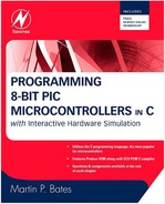
The test system shown in Figure 3.9 has only one I2C peripheral device, the 24AA256 serial flash memory chip, to keep it as simple as possible. Serial memory is a common feature of applications that require additional data storage, such as a data logger. It allows the internal EEPROM of the PIC to be expanded using only two I/O pins. The downside is that the memory access is rather slow, with the maximum write cycle time of 5 ms (200 bytes/sec) specified for this device. Therefore, the data sampling rate needs to be suitably modest.
Figure 3.9. I2C Test System

The serial memory chip has a capacity of 256- k bits, or 32- k bytes, with three external address pins: A0, A1, and A2. This allows a set of up to eight chips to be used in the system, each with a different hardware address, 0–7. This address is included in the address code sent by the master controller, so that a specific address in a selected chip can be accessed. With eight 32-k chips, the total address space is 256 k. In the test system, the memory chip hardware address is 000.
The system reads a test code set manually on Port B inputs, which is copied to the serial memory. Pull-ups must be fitted to the serial clock and data lines, and a virtual I2C analyzer is also attached to the bus. The test program writes the test byte (3F in the example shown) to the address lowadd, which increments from 0 after each write. The i2c_start() function initiates the data transfer sequence, by generating a start bit on the data line. This is followed by 4 bytes, containing control, address, and data codes.
The first is the control code, A0. The memory chip has a factory-set high address code of 0101(A). This distinguishes it from other types of I2C devices that may be added to the bus. The next 3 bits are the hardware address (000), and the LSB is set to 0 to indicate a write operation, making the low nibble 0000. This is followed by the two address bytes. The high address byte is 00, and the low address increments from 0, so the test program writes only to the first 256 bytes. The data byte follows, which is read in from the input switches.
Each of these bytes must be acknowledged by the receiving device taking the data line low, and the transfer is terminated by a stop bit. More details on the exact data format and timing requirements may be found in the chip data sheet.
The simulation system allows the bus activity to be logged and displayed in the I2C debug window using the virtual bus monitor instrument. A time stamp, the transfer codes, and the Start (S), Acknowledge (A), and Stop (P) bits are detected as they occur. In addition, the memory contents can be displayed to confirm the test data and which locations have been written.
When the memory content window is opened, we see that it retains the data from previous runs of the simulation, representing the nonvolatile nature of the data store. To see the data change, a new code must be set on the switches for each run.
The I2C functions are summarized in Table 3.8
| Operation | Description | Example |
|---|---|---|
| I2C WRITE | Send a single byte | i2c_write(outbyte); |
| I2C READ | Read a received byte | inbyte=i2c_read(); |
| I2C STOP | Issue a stop command in master mode | i2c_stop(); |
| I2C POLL | Check to see if byte received | sbit=i2c_poll(); |
.