After you have built and configured your Boe-Bot, you can start writing VPL applications to operate it. In this section, we will examine the steps necessary to build and execute a simple VPL application named BoeBotBumperTest. This application will be responsible for instructing your development machine to say "An object was detected" each time one of the IR detectors or whiskers is triggered. The IR detectors are triggered when an object passes within a few inches of the left or right IR detectors. The whiskers are triggered when one of them connects with the pins located on the Boe-Bot’s breadboard. If you have not already installed one of the contact sensor sets, you may wish to do so at this time.
Tip
While finalizing the assembly of your Boe-Bot, you may go back and forth between using the serial connection to execute test programs directly on the robot and using the wireless module to execute programs remotely with MSRS. If you do this, do not forget to reload the BoeBotControlForMsrsCtp2.bs2 program before you return to using MSRS. This driver program is what enables MSRS to communicate directly with the robot and must be the last program that is loaded onto the Boe-Bot.
To begin, you need to open the VPL tool by clicking Start, All Programs, Microsoft Robotics Studio (1.5), and then Visual Programming Language, which initiates a new VPL diagram. You can use the Find Service text box at the top of the Services toolbox, or you can scroll through the list until you locate the Generic Contact Sensors service. Drag this service onto the diagram surface. The Generic Contact Sensors service provides access to base functions that can be used by multiple robotics platforms.
To establish a link between the Generic Contact Sensors service and the Boe-Bot, you will need to configure the sensors service. You do this by double-clicking the service block in the main diagram. This opens the Set Configuration page where you can select Use A Manifest from the drop-down list box, and then click Import Manifest. The Import Manifest dialog box displays a list of manifest files supported by this service. You need to select the Parallax.MotorIrBumper.manifest.xml manifest and then click OK to tie this service to the Boe-Bot. It is this manifest file that informs the sensors service about which sensor should be monitored. By default, this manifest file is located in the samplesconfig folder for your local MSRS installation.
Remember, the Boe-Bot is not the only robot that you can use with the Generic Contact Sensors service. The Import Manifest dialog box contains a list of manifest files provided by other robotics hardware manufacturers. This list includes the following:
iRobot’s Create
LEGO’s NXT and RCX
MobileRobots’s Pioneer 3DX
fischertechnik’s Bionic Walker
Note
It is possible for the generic services to work with more robots than the ones listed here. For example, you may download services for another robot from the robot manufacturer’s Web site. Alternatively, you could create your own set of services for a custom-made robot. These custom-made robots can also potentially work with the generic services. If manifest files exist for these robots and the robots implement the generic services, they will also be listed in the Import Manifest list.
After the Generic Contact Sensors service is configured, you can return to the diagram tab by clicking on the tab at the top of the design surface. You will then need to drag and drop the data activity from the Basic Activities toolbox. Place the data activity to the right of the Generic Contact Sensors service. Click the text box inside the data activity block, select the 0 that is displayed by default, and type An object was detected. Next, select string as the data type.
To connect the two blocks, use your mouse to drag a line from the round Notification connector on the right side of the GenericContactSensors block to the input block on the left side of the Data block (see Figure 3-10). This action initiates the Connections dialog box and prompts you to select a From and To event. By default, the To event is Create. Click OK to close the Connections dialog box. Because you need to know when the IR sensor has detected an object, select ContactSensorUpdated as the From event.

Figure 3-10. To connect the GenericContactSensor and Data blocks, drag a connection between the round Notification connector and the left-hand side of the Data block.
Your next step is to drag the Text-to-Speech service onto the diagram and to the right of the Data block. This service supports several functions related to rendering text as speech through a Speech Application Programming Interface (SAPI)–compatible engine. A SAPI-compatible engine should already be located on your Windows development machine because the Microsoft Speech API version 5 has been available since the year 2000. If this is not the case, and you are encountering errors when trying to run programs using the text-to-speech service, you can download it free of charge from the Microsoft Web site: http://www.microsoft.com/downloads.
Note
MSRS includes services that provide speech recognition and speech synthesis capabilities for both a SAPI-compatible engine and the .NET 3.0 System.Speech library. The service we use in this chapter uses a SAPI-compatible engine and not the .NET 3.0 library.
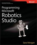
To connect the Data block to the Text-to-Speech service, drag a connector from the right side of the Data block to the left side of the Text-to-Speech block. This opens the Connections dialog box and prompts you to select a From and To value. Because you want to hear the text spoken, select SayText as the To value, and click OK to initiate the Data Connections dialog box (see Figure 3-11). This prompts you to select a value that will be set for the SpeechText variable. By default, the value selected is null. You must select Value from the drop-down list box; otherwise, no text will be spoken when you run the program. Click OK to close the Data Connections dialog box.
Figure 3-11. Use the Data Connections dialog box to select the value that will be set for the SpeechText variable.
Tip
If you forgot to select Value in the Data Connections dialog box, you can return to this dialog box by right-clicking the connector in the main diagram and selecting Data Connections. Alternatively, you can select the connection and use the Properties window on the right side of the screen to change the property assignment.
The SayText function will result in the text being spoken asynchronously or in parallel with all other processes called by the MSRS runtime. Alternatively, you could select SayTextSynchronously if you wanted to ensure that no other processes could execute while the text is spoken. Assuming the sound is enabled and you have desktop speakers installed on your development machine, you should hear the phrase "An object was detected" each time you pass your hand in front of the IR detectors or push on one of the whiskers.
Tip
You can find additional VPL examples in the Introductory Courseware available as a free download from the MSRS Web site. These helpful tutorials demonstrate how to perform complex tasks using VPL and a Create robot. Readers interested in these tutorials can download them from the following URL: http://www.microsoft.com/downloads/details.aspx?familyid=f294c8e7-6617-4dd8-8354-7e97f3167e1a.