
In this chapter, we will perform true parallel computing. The Neon coprocessor shares a lot of functionality with the FPU from Chapter 12, “Floating-Point Operations,” but can perform several operations at once. For example, you can achieve four 32-bit floating-point operations at once with one instruction. The type of parallel processing performed by the Neon Coprocessor is single instruction multiple data (SIMD) . In SIMD processing, each single instruction issued executes on multiple data items in parallel.
We’ll examine how to arrange data, so we can operate on it in parallel, and study the instructions that do so. We’ll then update our vector distance and 3x3 matrix multiplication programs to use the Neon processor to see how much of the work we can do in parallel.
The Neon Coprocessor shares the same register file we examined in Chapter 12, “Floating-Point Operations,” except that it can operate on all 128 bits of each register. We’ll learn how the bank of coprocessor registers is intended to be used with Neon. Let’s look in more detail at the NEON registers.
About the NEON Registers
The NEON Coprocessor can operate on the 64-bit registers that we studied in the previous chapter and a set of 128-bit registers that are new for this chapter. Having 128-bit registers doesn’t mean the NEON processor performs 128-bit arithmetic. Rather, the Neon Coprocessor segments the large register into holding multiple smaller values at once. For instance, one 128-bit register can fit four 32-bit single-precision floating-point numbers. If we multiply two such registers, all four 32-bit numbers are multiplied together at the same time resulting in another 128-bit register containing the four results.
The Neon Coprocessor operates on both integers and floating-point numbers. The greatest parallelism is obtained using 8-bit integers where 16 operations can happen at once.
The Neon coprocessor can operate on 64-bit D or 128-bit V registers; of course, if you use 64-bit D registers, you only have half the amount of parallelism. In all instructions, we refer to the V register, but the number of elements multiplied by the size of the element must always be either 64 bits or 128 bits.
Number of elements in each register type by size
8-Bit Elements | 16-Bit Elements | 32-Bit Elements | |
|---|---|---|---|
64 bits | 8 | 4 | 2 |
128 bits | 16 | 8 | 4 |
Stay in Your Lane
Designator and size for lanes
Designator | Size |
|---|---|
D | 64 bits |
S | 32 bits |
H | 16 bits |
B | 8 bits |

How register V1 can be divided into lanes. These lanes just specify the size and number of lanes, not the data type contained in them
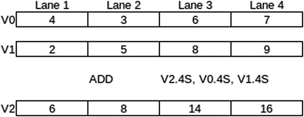
Example of the four lanes involved in doing 32-bit integer addition
Performing Arithmetic Operations
ADD Vd.T, Vn.T, Vm.T // Integer addition
FADD Vd.T, Vn.T, Vm.T // floating-point addition
For ADD: 8B, 16B, 4H, 8H, 2S, 4S or 2D
For FADD: 4H, 8H, 2S, 4S or 2D
We use the same instructions as we used for scalar integer and floating-point arithmetic. The Assembler knows to create code for the NEON Coprocessor due to the use of V registers and the inclusion of the T specifier.
The trick to using NEON is arranging your code, so that all the lanes keep doing useful work.
Since the NEON Processor supports integer operations, it supports all the logical operations like AND, BIC, and ORR. There are also a selection of comparison operations.
A look at the list of NEON instructions shows a lot of specialty instructions provided to help with specific algorithms. For example, there’s direct support for polynomials over the binary ring to support certain classes of cryptographic algorithms.
We will show you how to use a few of the instructions in working examples. This will give you enough knowledge to apply the general principles of operations for the NEON Coprocessor; then you can peruse all the instructions in the ARM Instruction Set Reference Guide.
Calculating 4D Vector Distance
Let’s expand the distance calculation example from Chapter 12, “Floating-Point Operations,” to calculate the distance between two four-dimensional (4D) vectors. The formula generalizes to any number of dimensions, by just adding the extra squares of the differences for the additional dimensions under the square root.
Routine to calculate the distance between two 4D vectors using the NEON Coprocessor.
The main program to test the 4D distance function.
The makefile for the distance program
- 1.
We load one vector into V2 and the other into V3. Each vector consists of four 32-bit floating-point numbers, so each one can be placed in a 128-bit V register and treated as four lanes.
- 2.
Subtract all four components at once using a single FSUB instruction. We calculate the squares all at once using a FMUL instruction. Both instructions operate on all four lanes in parallel.
- 3.
Add up all the sums which are all in V1. This means all the numbers are in different lanes and we can’t add them in parallel. This is a common situation to get into; fortunately the NEON instruction set does give us some help. It won’t add up all the lanes in a register, but it will do pairwise additions in parallel. The following instruction
FADDP V0.4S, V1.4S, V1.4S
will pairwise add each pair of 32-bit floating-point numbers in the two arguments, putting all the sums in V0. Since the results have half the number of elements as the arguments, we can pairwise add four pairs in this case, which can be held in two V registers. We only need the first two sums, so we ignore the results from the second operand. This accomplishes two of the additions we need.
- 4.
Perform the third using another FADDP instruction. This leaves the result we want in lane 1 which happens to overlap the regular floating-point register S0.
- 5.
Once the numbers are added, use the FPU’s square root instruction to calculate the final distance.
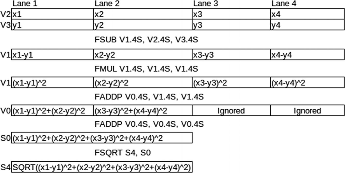
Flow of the calculations through the registers showing the lanes. The last two lines aren’t to scale and only show a single lane
This shows a nice feature of having the NEON and FPU sharing registers, allowing intermixing of FPU and NEON instructions without needing to move data around.
The only change to the main program is making the vectors 4D and adjust the loop to use the new vector size.
Optimizing 3x3 Matrix Multiplication
Let’s optimize the 3x3 matrix multiplication example program from Chapter 11, “Multiply, Divide, and Accumulate,” by using the parallel processing abilities of the NEON Coprocessor.
The NEON Coprocessor has a dot product function SDOT, but sadly it only operates on integers and isn’t available on all processors. Hence, we won’t use it. As we saw in the last example, adding within one register is a problem, and similarly there are problems with carrying out multiply with accumulates.
The recommended solution is to reverse two of our loops from the previous program. This way we do the multiply with accumulates as separate instructions, but we do it on three vectors at a time. The result is we eliminate one of our loops from the previous program and achieve some level of parallel operation.
Ccol1 = A ∗ Bcol1
Ccol2 = A ∗ Bcol2
Ccol3 = A ∗ Bcol3
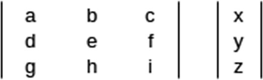
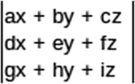
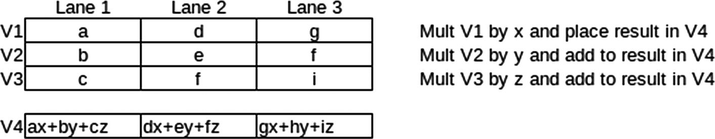
Showing how the calculations flow through the lanes
This is the recommended algorithm for matrix multiplication on the NEON coprocessor. We will use short integers to demonstrate integer arithmetic this time. Since four 16-bit short integers fit into 64 bits and we only need three, we will use this lane configuration.
What we did above is for one column of the results matrix, we then need to do this for all the columns. We will place this logic in a macro, to repeat the calculation three times. Since the goal is as fast matrix multiplication as possible, it is worth removing the loops, since it saves extra logic. This makes the program look much simpler.
Neon-enabled 3x3 matrix multiplication example
We store both matrices in column major order and the C matrix is produced in column major order. This is to make setting up the calculations easier, since everything is aligned properly to bulk load into our NEON registers. We changed the print loop, so that it prints out the results matrix in our usual row order form, basically doing a matrix transpose as it loops through the C matrix.
This is multiplying each lane in V0 by the scalar contained in a specific lane of V3. This shows how we typically access a value in a specific lane by appending [lane number] to the end of the register specifier—counting lanes from zero.
We added ( ) after the parameter name, since otherwise the .4H will be included and the parameter won’t expand correctly. The ( ) is just a null expression to introduce a separator between the macro parameter name and the next characters.
Summary
This chapter is a quick overview of how the NEON Coprocessor works and how to write programs for it. We explained how NEON uses lanes to perform parallel computations and a selection of the instructions available for computations. We gave two examples, one to calculate the distance between two 4D vectors and one to perform 3x3 matrix multiplication to demonstrate how you can easily harness the power of the NEON Coprocessor.
In Chapter 14, “Optimizing Code,” we’ll look at specialized instructions to optimize conditional logic and show how to optimize our upper-case routine.
Exercises
- 1.
Compute the absolute value of a 4D vector. A 4D vector v, given by (a, b, c, d), has an absolute value square root (a2 + b2 + c2 + d2).
- 2.
The length of a vector is its distance from the origin, the vector of all zeros. A normalized vector is a vector with length 1. Normalize a vector by dividing each of its components by its length. Modify the distance program to compute the normalized form of a vector.
- 3.
Write a routine to calculate the dot product of two 4D vectors.
- 4.
Alter the 3x3 matrix program to multiply 4x4 matrices. Make sure you verify your result is correct.