
Techniques for Audio Loss Concealment
Techniques for Video Loss Concealment
Interleaving
Earlier chapters described how RTP running over UDP/IP provides an unreliable packet delivery service, and how this means an application may have to deal with an incomplete media stream. There are two things the application can do when packet loss occurs: try to correct the error, or try to conceal it. Error correction is discussed in Chapter 9. In this chapter we discuss techniques by which a receiver can conceal the effects of loss.
When an RTP packet containing audio data—whether music or speech—is lost, the receiver has to generate a replacement to preserve the timing of the media stream. This can be done in many ways, and the choice of concealment algorithm can have a significant impact on the perceived quality of the system in the case of loss.
Human perception of sound is a complex process, and the perceptual significance of distortion depends not just on the amount the signal has changed, but also on the type of damage caused, and where it occurred in the signal. Some types of distortion are more noticeable to listeners than others, even if—by some objective measure—they change the signal by the same amount. It is also common for different listeners to perceive a particular type of distortion in different ways, and to rate concealment schemes differently depending on the material to which they are applied.
This makes it very difficult to devise objective quality measurements for different repair schemes. It is not sufficient to measure the difference between the original waveform from the source and the waveform recovered at the receiver, because the perceived quality has no direct relation to the differences in the waveforms. Simple measures, such as the signal-to-noise ratio, are effectively useless. More complex schemes (for example, those in ITU recommendations P.861 and P.86263,64) give results that are approximately correct for speech, but even these are not 100% reliable.
When objective measurements fail, we need to resort to subjective tests. By conducting listening tests with a wide range of subjects, materials, and error conditions, we can measure the effectiveness of different repair schemes in a manner meaningful to the listener. These tests involve playing different types of music, or a range of words, phrases, and sentences subject to different error conditions and concealment techniques, with the listener rating their quality and/or intelligibility according to a particular scale.
The choices of material and rating scale depend on what is being measured. If you are attempting to measure the perceived quality of speech (“does it sound good?”), then rating samples on the basis of a Mean Opinion Score (MOS) is appropriate. The MOS is a five-point rating scale, the results of which are converted into numeric form (excellent = 5, good = 4, fair = 3, poor = 2, bad = 1) and averaged across all the listeners, giving a numeric result between 1 and 5. For the results to be statistically valid, it is necessary to make a large number of tests comparing different samples.
Typical MOS scores for unimpaired speech are 4.2 for the G.711 codec (that is, standard telephone quality) and between 3.5 and 4 for mobile telephony (for example, GSM, QCELP). Packet loss will lower these numbers, with the degree of loss and the type of concealment determining the actual result.
MOS scores provide a reasonable measure of perceived quality, allowing comparison between different codecs and repair techniques, but they do not measure intelligibility (that is, whether the audio is understandable). There is a difference between what sounds good and what conveys information; it is possible to define a concealment scheme that gets very good marks for sound quality but may not produce intelligible speech. In tests for intelligibility, listeners copy down sentences or words played with different impairments, or answer questions on a passage of text, and the result is a measure of how many errors are made. Again, a large number of tests must be conducted for the results to be statistically meaningful.
Perhaps the most important point learned from listening tests is that the results vary depending on the persons listening, the material they are listening to, the type of distortion present in the sound, and the task they are performing. Depending on the application, it may be important to conduct tests of both perceived quality and intelligibility, and it is always necessary to ensure that the test material and packet loss rates match those of typical usage.
The simplest possible repair technique is silence substitution, in which gaps caused by packet loss are filled with silence of the appropriate duration, as shown in Figure 8.1. This is the cheapest and easiest method to implement, and one of the most commonly used techniques.
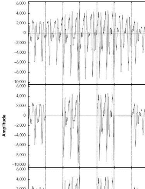
Figure 8.1. Repair Using Silence Substitution (Adapted from C. Perkins, O. Hodson, and V. Hardman, “A Survey of Packet Loss Recovery Techniques for Streaming Media,” IEEE Network Magazine, September/October 1998. © 1998 IEEE.)
Unfortunately, silence substitution is also the worst repair scheme, consistently rated last in listening tests designed to evaluate repair quality.114 Listening trials have shown that silence substitution is effective only with short-duration packets (<16 milliseconds) and low packet loss rates (<2%). Performance degrades rapidly as the packet size and loss rate increase, becoming rapidly unusable with the packet sizes used in voice-over-IP applications, and with the loss rates encountered in many networks.75,82
Implementations should not use silence substitution. Any of the techniques described next will give better-quality sound, with a very small increase in complexity.
Because silence substitution has been shown to perform poorly, the next choice is to fill the gap left by a lost packet with background noise of some sort—a process known as noise substitution (see Figure 8.2).
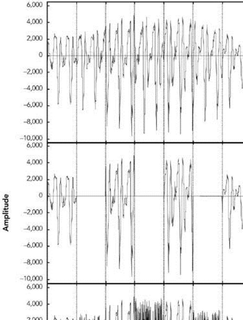
Figure 8.2. Repair Using Noise Substitution (Adapted from C. Perkins, O. Hodson, and V. Hardman, “A Survey of Packet Loss Recovery Techniques for Streaming Media,” IEEE Network Magazine, September/October 1998. © 1998 IEEE.)
At its simplest, noise substitution is the addition of white noise—noise with uniform amplitude at all frequencies—in place of the missing signal, amplitude matched to the previous packet. Here it is represented in pseudocode:
void
substitute_noise(sample previous_frame[samples_per_frame],
         sample missing_frame[samples_per_frame)
{
    double energy;

    // Calculate energy (amplitude) of the previous frame
    energy = 0.0;
    for(j = 0; j < samples_per_frame; j++) {
        energy += previous_frame[j] * previous_frame[j];
    }
    energy = sqrt(energy);
    // Fill in the noise
    for(j = 0; j < samples_per_frame; j++) {
        missing_frame[j] = energy * random(-1,1);
    }
}
Note that a real implementation will likely replace the arrays with a rotating buffer of the last few frames received, discarding old frames after they have been played out.
Listening tests with speech have shown that, when compared to silence substitution, the use of white-noise substitution with approximately the same amplitude as the signal gives both subjectively better quality88 and improved intelligibility.114 There is a perceptual basis to this improvement in quality: Studies have shown that phonemic restoration, the ability of the human brain to subconsciously repair missing segments of speech with the correct sound, occurs for speech repaired with noise, but not when silence is used as the repair. Because white noise is almost as easy to generate as silence, it is to be recommended as a replacement for silence substitution.
If the spectral characteristics of the signal are known, it may be possible to tailor the generated noise to match the original more closely than can be done with white noise. Many payload formats facilitate this task by providing comfort noise indicator packets to be sent during silence periods. Support for comfort noise allows the receiver to play an appropriate form of background noise when there is otherwise nothing to hear, and it can make the system seem more natural.
For payload formats that don't include native support for comfort noise, there is a standard comfort noise payload format that may be used to transport this information (static payload type 13 in the default audio/video profile42). This comfort noise format conveys two pieces of information: the amplitude of the noise, and the spectral parameters. The amplitude allows the receiver to generate amplitude-matched noise; the spectral parameters enable shaping of the noise to match the surrounding signal.
Depending on the content of the audio signal, it may be possible to provide a replacement for a lost packet that is somewhat similar to the original. This is especially true of speech signals, which are interspersed with repetitive patterns, known as pitch cycles, that typically last from 20 milliseconds to 100 milliseconds. Losses that occur during pitch cycles have a good probability of being concealed.
Figure 8.3 shows a typical speech signal. Although many features can be recognized, the main differentiation is between voiced and unvoiced speech. Voiced speech, generated by the periodic opening and closing of the vocal folds (commonly called the vocal cords), generates regular, high-amplitude pitch cycles with frequency in the approximate range of 50Hz to 400Hz. Voiced segments often last for many tens or even hundreds of milliseconds, allowing the loss of a single packet of voice speech to be effectively repaired by substitution of the contents of the preceding packet. This phenomenon is reflected in Figure 8.4, which shows that loss repaired by repetition can be very similar to the original, except for the sharp discontinuity at the edges of the repaired region.

Figure 8.4. Repair of Voiced Speech Using Packet Repetition (Adapted from C. Perkins, O. Hodson, and V. Hardman, “A Survey of Packet Loss Recovery Techniques for Streaming Media,” IEEE Network Magazine, September/October 1998. © 1998 IEEE.)
Unvoiced speech—consisting of sounds such as s, f, and sh—is generated by air being forced through a constriction in the vocal folds, and it closely resembles low-amplitude noise. Again, replacing a lost period of unvoiced speech with the contents of the previous packet produces reasonably good repair.
Repetition clearly works best when the gap is small, because the characteristics of the signal are likely to be similar across the gap. One can improve the performance of repetition with longer gaps by gradually fading the repeated signal. For example, the GSM mobile telephony system recommends an identical repeat for the first lost packet, followed by a gradual fade to zero amplitude over the next 16 packets (320 milliseconds total duration), or until the next packet is received.60
The repetition algorithm can be outlined in pseudocode like this:
void
repeat_and_fade_frame(sample previous_frame[samples_per_frame],
              sample missing_frame[samples_per_frame],
              int consecutive_lost)
{
    // Repeat previous frame
    for (j = 0; j < samples_per_frame; j++) {
        missing_frame[j] = previous_frame[j];
    }
    // Fade, if we've lost multiple consecutive frames
    if (consecutive_frames_lost > 0) {
        fade_per_sample = 1 / (samples_per_frame *
        fade_duration_in_frames);
        scale_factor = 1.0 – (consecutive_frames_lost *
                              samples_per_frame * fade_per_sample);
        if (scale_factor <= 0.0) {
            // In case consecutive_frames_lost >
            // fade_duration_in_frames
            scale_factor = fade_per_sample = 0.0;
        }
        for (j = 0; j < samples_per_frame; j++) {
            missing_frame[j] *= scale_factor
            scale_factor -= fade_per_sample
        }
    }
}
Note that the previous_frame[] array represents the previous frame received, not any previously repaired frame. The playout buffer should maintain the variable consecutive_lost based on the RTP sequence numbers, and should keep track of original versus repaired frames (in case one of the original frames was merely delayed).
Listening tests show that repetition works better than noise substitution for speech signals, and it is simple to implement. Repetition works better with speech than with music because the characteristics of music are more varied. Noise matched to the frequency spectrum of the signal may be a better choice for music signals.
The three simple repair techniques—silence substitution, noise substitution, and repetition—form the basis of many error concealment systems, and when correctly applied they can give good performance with low implementation complexity. Researchers have also studied a range of more specialized error concealment techniques for speech. These techniques typically trade increased complexity of implementation for a modest improvement in performance, and they are often tailored to particular types of input.
Various techniques based on waveform substitution have been proposed for use with speech. These techniques generate a suitable replacement packet based on characteristics of the speech signal surrounding a lost packet, and they can be viewed as extensions of packet repetition. Unlike basic packet repetition, waveform substitution algorithms adapt the repair to avoid discontinuity at the edges of the gap, and to match the characteristics of the signal better.
As an example of waveform substitution, consider the algorithm proposed by Wasem et al.,107 building on earlier work by Goodman et al.74 This algorithm first classifies speech as voiced or unvoiced (for example, by detecting the periodic spikes due to voiced pitch cycles). If the speech surrounding the loss is unvoiced, packet repetition is used to fill the gap. If the surrounding speech is voiced, a pattern-matching repair algorithm is used to find the region to repeat.
The pattern-matching repair algorithm uses the last few milliseconds of speech before the gap as a template. A sliding window algorithm is then used to compare the template with the rest of the packet, noting the location of the best match. The region between the template and its best match forms a complete pitch cycle, which is repeated to fill in the gap. Because the template closely matches the original, there is no significant discontinuity at the start of the repair. In pseudocode, the algorithm can be written this way:
void pattern_match_repair(sample previous_frame[samples_per_frame],
                          sample missing_frame[samples_per_frame],
                          int    consecutive_frames_lost)
{
    // Find best match for the window of the last few samples
    // in the packet
    window_start = samples_per_frame - window_length;
    target = infinity;
    for(i = 0; i < window_start; i ++) {
        score = 0;
        for(j = i, k = 0; k < window_length; j++, k++) {
             score += previous_frame[j] -
                                  previous_frame[window_start + k];
        }
        if (score < target) {
            target = score;
            best_match = i; // The start of the best match for the
                            // window
        }
    }
    pattern = best_match + window_length;
    pattern_length = samples_per_frame – pattern;
    // "pattern" now points to the start of the region to repeat.
    // Copy the region into the missing packet
    dest = 0;
    for (remain = samples_per_frame; remain > 0;
                                         remain -= pattern_length) {
        for (j = 0; j < min(remain, pattern_length); j++) {
            missing_frame[dest++] = previous_frame[pattern + j];
        }
    }
    // Fade, if we've lost multiple consecutive frames
    if (consecutive_frames_lost > 0) {
        fade_buffer(missing_frame, consecutive_frames_lost);
    }
}
There is still a boundary discontinuity at the end of the repair. We can patch this by merging the repair with the original data, provided that the two overlap. Such a patch is illustrated in Figure 8.5, where the weighted average of the two waveforms is used in the overlap region, providing a smooth transition. Weighting means to take more of the first waveform at the beginning of the overlap region and more of the second waveform at the end.
The result is a very effective repair algorithm for speech, which noticeably outperforms repetition. A sample speech waveform repaired by waveform substitution is shown in Figure 8.6.

Figure 8.6. Repair Using Waveform Substitution (Adapted from C. Perkins, O. Hodson, and V. Hardman, “A Survey of Packet Loss Recovery Techniques for Streaming Media,” IEEE Network Magazine, September/October 1998. © 1998 IEEE.)
Researchers have proposed a seemingly endless series of error concealment techniques that offer incremental improvements over those discussed here. These techniques include the following:
Timescale modification,. which stretches the audio on either side of a loss across the gap. For example, Sanneck et al.102 have proposed a scheme in which pitch cycles are stretched to cover the loss from either side, and averaged where they meet.
Regenerative repair,. which uses knowledge of the audio compression algorithm to derive the appropriate codec parameters to recover a lost packet.
Interpolation of codec state,. which allows codecs based on linear prediction (for example, G.723.1) to derive the predictor coefficients by interpolating the frames on either side of a loss.
Model-based repair,. which attempts to fit the signals on either side of the loss to a model of the vocal tract/codec, and uses this model to predict the correct fill-in.
Applications that deal solely with speech may want to consider these more complex repair schemes. Be aware, however, that the gains are incremental and the increase in complexity is considerable (see Figure 8.7 for a rough chart of quality versus complexity).

Most video codecs use interframe compression, sending occasional full frames and many intermediate frames as updates to the parts of the frame that have changed or moved, as shown in Figure 8.8. This technique, known as predictive coding because each frame is predicted on the basis of the preceding frame, is essential for good compression.
Predictive coding has several consequences for loss concealment. The first is that loss of an intermediate frame may affect only part of a frame, rather than the whole frame (similar effects occur when a frame is split across multiple packets, some of which are lost). For this reason, concealment algorithms must be able to repair damaged regions of an image, as well as replace an entire lost image. A common way of doing this is through motion-compensated repetition.
The other consequence of predictive coding is that frames are no longer independent. This means that loss of data in one frame may affect future frames, making loss concealment more difficult. This problem is discussed in the section titled Dependency Reduction later in this chapter, along with possible solutions.
One of the widely used techniques for video loss concealment is repetition in the time domain. When loss occurs, the part of the frame affected by the loss is replaced with a repeat of the preceding frame. Because most video codecs are block based, and the missing data will often constitute only a small part of the image, this type of repair is usually acceptable.
Of course, repetition works only if the image is relatively constant. If there is significant motion between frames, repeating a portion of the preceding frame will give noticeable visual artifacts. If possible, it is desirable to detect the motion and try to compensate for it when concealing the effects of loss. In many cases this is easier than might be imagined because common video codecs allow the sender to use motion vectors to describe changes in the image, rather than sending a new copy of moved blocks.
If only a single block of the image is lost, a receiver may use the motion vectors associated with the surrounding blocks to infer the correct position for the missing block, on the basis of the preceding packet. For example, Figure 8.9 shows how the motion of a single missing block of the image can be inferred. If the highlighted block is lost, the original position can be derived because the motion is likely the same as that for the surrounding blocks.

Motion-compensated repetition relies on loss affecting only a part of the image. This makes it well suited to network transport that corrupts single bits in the image, but less suited to transport over IP networks that lose packets containing several, most likely adjacent, blocks. Interleaving—discussed later in this chapter—is one solution to this problem; another is to use the motion vectors from the preceding frame to infer the motion in the current frame, as shown in Figure 8.10. The assumption here is that motion is smooth and continuous across frames—an assumption that is not unreasonable in many environments.

The two schemes can work together, inferring lost data either from other blocks in the current frame or from the previous frame.
It is recommended that implementations should, at least, repeat the contents of the preceding frame in the event of packet loss. It is also worth studying the codec operation to determine whether motion compensation is possible, although this is a lesser benefit and may be predetermined by the design of the codec.
Besides repetition, two other classes of repair may be used: repair in the spatial domain and repair in the frequency domain.
Repair in the spatial domain relies on interpolation of a missing block, on the basis of the surrounding data. Studies have shown that human perception of video is relatively insensitive to high-frequency components—detail—of the image. Thus a receiver can generate a fill-in that is approximately correct, and as long as this is just a transient, it will not be too visually disturbing. For example, the average pixel color for each of the surrounding blocks can be calculated, and the missing block can be set to the average of those colors.
Similar techniques can be applied in the frequency domain, especially for codecs based on the discrete cosine transform (DCT), such as MPEG, H.261, and H.263. In this case the low-order DCT coefficients can be averaged across the surrounding blocks, to generate a fill-in for a missing block.
Simple spatial and temporal repair techniques give poor results if the error rate is high, and generally they do not work well with packet loss. They work better with networks that give bit errors, and they corrupt a single block rather than losing an entire packet containing several blocks. There are various more advanced spatial and temporal repair techniques—the surveys by Wang et al.105,106 provide a good overview—but again, these are generally unsuited to packet networks.
Although predictive coding is essential to achieving good compression, it makes the video sensitive to packet loss and complicates error concealment. On the other hand, if each frame of video is independently coded, a lost packet will affect only a single frame. The result will be a temporary glitch, but it will rapidly be corrected when the next frame arrives. The penalty of independently coded frames is a much higher data rate.
When predictive coding is used and the frames are not independent, loss of a single packet will propagate across multiple frames, causing significant degradation to the video stream. For example, part of a frame is lost and has to be inferred from the preceding frame, producing a repair that is, by necessity, inexact. When the next frame arrives, it contains a motion vector, which refers to the part of the image that was repaired. The result is that the incorrect data remains in the picture across multiple frames, moving around according to the motion vectors.
Error propagation in this manner is a significant problem because it multiplies the effects of any loss and produces results that are visually disturbing. Unfortunately, there is little a receiver can do to correct the problem, because it has insufficient data to repair the loss until a complete frame update arrives. If the loss exceeds a particular threshold, a receiver might find it better to discard frames predicted from lost data, displaying a frozen image, than to use the erroneous state as a basis and display damaged pictures.
A sender can ease this problem by using less predictive coding when packet loss is present, although doing so may reduce the compression efficiency and lead to an increase in the data rate (see Chapter 10, Congestion Control, for a related discussion). If possible, senders should monitor RTCP reception report feedback and reduce the amount of prediction as the loss rate increases. This does not solve the problem, but it means that full frame updates occur more often, allowing receivers to resynchronize with the media stream. To avoid exceeding the available bandwidth, it may be necessary to reduce the frame rate.
There is a fundamental trade-off between compression efficiency and loss tolerance. Senders must be aware that compression to very low data rates, using predictive coding, is not robust to packet loss.
At the start of this chapter, it was noted that error concealment is something done by a receiver, without help from the sender. In general this is the case, but sometimes a sender can ease the task of error concealment without having to send extra information. One such example was noted for video, in which a sender can reduce the interframe dependency to ease the job of a receiver. A more general-purpose technique is interleaving, which can be used with both audio and video streams, as long as low delay is not a requirement.
The interleaving process reorders data before transmission so that originally adjacent data is separated by a guaranteed distance during transport. Interleaving is useful because it makes bursts of consecutive packet loss in the transport stream appear as isolated losses when the original order is restored. In Figure 8.11, for example, the loss of four consecutive packets in the interleaved stream is transformed into four single-packet losses when the original order is reconstructed. The actual loss rate is unchanged, but it is typically easier for a receiver to conceal a series of single-packet losses than it is to conceal a longer burst of loss.

Figure 8.11. Interleaving, Transforming Burst Loss to Isolated Loss (From C. Perkins, O. Hodson, and V. Hardman, “A Survey of Packet Loss Recovery Techniques for Streaming Media,” IEEE Network Magazine, September/October 1998. © 1998 IEEE.)
The simplest implementation of an interleaving function is with a pair of matrices, as shown in Figure 8.12. Frames of media data are read into the first matrix by rows until that matrix is full. At that time the two matrices are switched, with data being read out of the first by columns, as the second is filled by rows. The process continues, with frames being read into one matrix as they are read out of the other.
Both sender and receiver must maintain buffer matrices as arrays of an appropriate size. The sender takes the output by columns and inserts it into packets for transport. The receiver takes the packets from the transport stream and passes them into the matrix buffer by rows, and as they are read out by columns the original order is restored.
Interleaving may be done at the RTP packet level, but more often multiple frames within each packet are interleaved. When interleaving is done at the RTP packet level, the codec data is packed into RTP packets as usual. The interleaving operates on complete packets, resulting in a series of packets that have nonconsecutive RTP timestamps. The RTP sequence number should be generated after interleaving, resulting in packets that have consecutive sequence numbers as sent.
When interleaving is done with multiple frames within each packet, the RTP timestamp and sequence number are unchanged from the noninterleaved format. Putting multiple codec frames into each RTP packet so that each column of the interleaver forms an RTP packet keeps these values constant.
The interleaving function should be chosen so that adjacent packets in the original stream are separated by more than the maximum consecutive loss length in the transport stream. A matrix-based implementation with n rows of m columns will produce output with originally adjacent symbols separated by n others. Put another way, as m or fewer packets are lost during transport of each matrix, each group of n packets after deinterleaving will have at most one loss.
The transport process must communicate the size of the interleaving group—the dimensions of the matrix—and the position of each packet within that group. The size of the interleaving group may be fixed and communicated out of band, or it may be included within each packet, allowing the interleaving function to vary. The position of each packet within an interleaving group must be included with the packet if the group size can vary, or it may be inferred from the RTP sequence number if the group size is fixed.
A good example of the use of interleaving is the loss-tolerant payload format for MPEG Audio Layer-3 (MP3),38 which was developed in response to the lack of resilience of the original payload format12 to packet loss. Other examples of interleaving may be found in the payload formats for AMR (Adaptive Multi-Rate) and AMR-WB (Adaptive Multi-Rate Wideband) audio.41 There is no single standard for interleaving; each payload format must implement it individually.
Interleaving adds considerable latency to the transmission process.97 The same number of packets as in the interleave group at both sender and receiver will be buffered. For example, if a 5 × 3 matrix implementation is used, 15 packets will be buffered at the sender, and 15 at the receiver, in addition to the network delay. This makes interleaving unsuitable for interactive applications; however, interleaving works well for streaming.
One of the key points to remember when designing an RTP application is robustness. Error concealment is a major part of this, allowing the application to operate even when the network misbehaves. A good error concealment scheme provides the difference between a tool that can be used in the real world and one that continually fails when subjected to the wide variation in loss rates inherent in the Internet. For this reason, all applications should implement some form of error concealment.