
In this project, we will use a pair of DC motors to drive the robot. We will use a dual H-bridge (SN754410) driver to control the DC motors. We will use a software PWM library written for the Raspberry Pi. We chose DC motors for the following reasons:
- DC motors are easy to operate and control using an H-bridge interfaced to the Raspberry Pi.
- There is a software PWM library that makes it easier to control the DC motors.
In this task, we will implement the DC motor control circuit and also write a program to control the DC motors.
We will use the software PWM function available with RPi.GPIO. The software PWM function is available on versions greater than 0.5.3. We need to determine the RPi.GPIO version installed on the Raspberry Pi using a command-line terminal:
python
import RPi.GPIO
RPi.GPIO.VERSION
If the returned value is earlier than 0.53, the package can be updated as follows:
sudo apt-get update
sudo apt-get upgrade
We will be making use of pulse width modulation to drive the DC motors. It is important that you familiarize yourself with pulse width modulation techniques to control a DC motor. We also need to set up the DC motors for testing by connecting the wheels to the motor (something similar to the following figure):
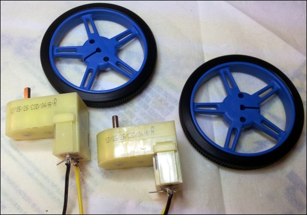
DC motors with soldered wires and wheels with strapped silicone tires
We also need to construct the motor control circuitry as shown in the following schematic:

A SN754410 motor control circuitry
An H-bridge circuit is used for bidirectional control of a DC motor using a microcontroller or Raspberry Pi (https://itp.nyu.edu/physcomp/labs/motors-and-transistors/dc-motor-control-using-an-h-bridge/). The H-Bridge takes in 2 inputs for each motor. The following table shows a logic table that dictates the control of a motor using an H-Bridge:

The SN754410 truth table
For example, if pin 1A is set to high while 2A is set to low and the leads of the motor are connected to 1Y and 2Y respectively, the motor rotates in one direction, while it rotates in the opposite direction when 1A is set to low and 2A is set to high.
- We will get started with the testing of the DC motors with a simple Python program. We will get started by importing the modules:
import RPi.GPIO as GPIO
import time
- We will declare the pins that will be used as output pins. We will connect the GPIO pins, 8, 9, 10, and, 11 to motor driver pins, 1A, 2A, 3A, and 4A, respectively:
GPIO.setwarning(False)
GPIO.setmode(GPIO.BCM)

GPIO.setup(8,GPIO.OUT) #connected to 1A
GPIO.setup(9,GPIO.OUT) #connected to 2A
GPIO.setup(10,GPIO.OUT) #connected to 3A
GPIO.setup(11,GPIO.OUT) #connected to 4A
- We test both the motors by rotating them in both directions for 10 seconds and stopping them:
while True:
#Rotate both motors forward for 10 seconds
GPIO.output(8,GPIO.HIGH)
GPIO.output(9,GPIO.LOW)

GPIO.output(10,GPIO.HIGH)
GPIO.output(11,GPIO.LOW)
sleep(10)
#Stop motors and rotate in reverse directions
GPIO.output(8,GPIO.LOW)
GPIO.output(10,GPIO.LOW)
#Go reverse
GPIO.output(9,GPIO.HIGH)
GPIO.output(11,GPIO.HIGH)
sleep(10)
#Stop motors and rotate both in opposite directions
GPIO.output(9,GPIO.LOW)
GPIO.output(11,GPIO.LOW)

GPIO.output(8,GPIO.HIGH)
GPIO.output(9,GPIO.LOW)

GPIO.output(10,GPIO.LOW)
GPIO.output(11,GPIO.HIGH)
sleep(10)
#Stop Motors
GPIO.output(8,GPIO.LOW)
GPIO.output(9,GPIO.LOW)
GPIO.output(10,GPIO.LOW)
GPIO.output(11,GPIO.LOW)
- In the preceding example, both the motors were running at 100 percent duty cycle. We will look into controlling the motors using pulse width modulation. We will set the pins as output and declare the operating channel frequencies for the PWM pins (1kHz):
GPIO.setup(8,GPIO.OUT) #connected to 1A
GPIO.setup(9,GPIO.OUT) #connected to 2A
GPIO.setup(10,GPIO.OUT) #connected to 3A
GPIO.setup(11,GPIO.OUT) #connected to 4A

GPIO.output(9,GPIO.HIGH)
GPIO.output(11,GPIO.HIGH)

motor1 = GPIO.PWM(8,1000)
motor2 = GPIO.PWM(10,1000)
- We will start the pulse width modulation signal (10 percent duty cycle – runs at 10 percent of the rated voltage) as follows:
motor1.start(10)
motor2.start(10)
- We can vary the speed of the motor as follows:
while True:
motor1.ChangeDutyCycle(25)
motor2.ChangeDutyCycle(25)
sleep(15)
motor1.ChangeDutyCycle(50)
motor2.ChangeDutyCycle(50)
sleep(15)
motor1.ChangeDutyCycle(75)
motor2.ChangeDutyCycle(75)
sleep(15)
motor1.ChangeDutyCycle(100)
motor2.ChangeDutyCycle(100)
sleep(15)
- We can vary the speed of the motor as follows: