
In this task, we will assemble the robot in simple steps that are accompanied by a photographical representation.
We need to have the following parts ready to assemble the robot:
- Top and bottom chassis plates for the line following robot
- Infrared sensors
- A pair of #2 screws and nuts (washers optional)
- A ball caster assembly with screws from Pololu
- 2*M2.5 screws for mounting the Raspberry Pi (washers optional)
- 4*#6 1-inch screws with spacers (washers optional)
- A Raspberry Pi
- Velcro
- Battery
- 2 DC motors
- Double-sided tape
- A Pi Plate
- A motor driver
- We will get started by mounting the castor wheel.

Mounting the castor wheel
- We will mount the Raspberry Pi using M2.5 screws.

Raspberry Pi mounted using M2.5 screws
- This is followed by the DC motors coupled with wheels using the double-sided tape. The DC motors with a plastic gearbox from Pololu do not come with a mounting hole, and hence, we will use double-sided tape to mount the motors. Similarly, the infrared sensors were also mounted using double-sided tape at the center with a spacing that is half the width of the track.
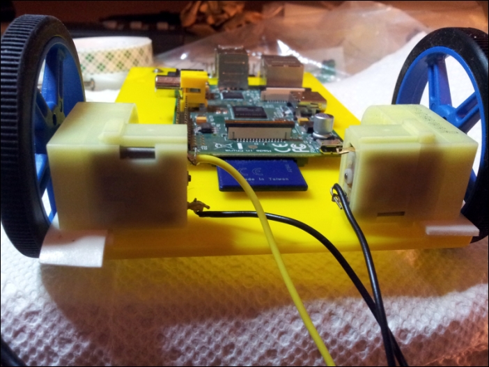
DC motors mounted using double-sided tape
- We will mount the Pi Plate and the top chassis plate. We will use velcro to mount the USB battery pack to complete the line following robot assembly.

An assembled robot
- Once the assembly is completed, we have to connect the motors and the sensors to get started with the testing.
We have completed the assembly of the line following robot in this task. Once the motor control code is implemented into the line following logic, we are all set to testing the robot on the track. This may require some tweaking the motor speed to make the robot track the line effectively.
..................Content has been hidden....................
You can't read the all page of ebook, please click here login for view all page.