
Chapter 6. Hardware: Tools and Supplies
Byrne’s Law: In any electrical circuit, appliances and wiring will burn out to protect fuses.
Although it may be possible that one could implement a complex instrumentation system and never touch a tool more complicated than a screwdriver, there is a high probability that a soldering iron, wire cutters, and a digital multimeter (DMM) will come in handy at some point—particularly if things don’t work quite right from the outset, or if there’s a reason to be concerned should something accidentally be damaged.
In this chapter, we’ll look at what might go into a basic toolkit for doing instrumentation work. It isn’t much and could all easily fit in a small box on a shelf somewhere. Additionally, as there may very well come a time when you really need to see what’s going on in your system, I’ve included a short discussion of the two pieces of test equipment that can help eliminate the guesswork and get to the root of an interface or control problem: the oscilloscope and the logic analyzer.
The Essentials
First and foremost, one needs some decent hand tools. These can be had à la carte from the local hardware store, or in a kit form in a nice zippered carrying case. Having even a modest set of hand tools available can make the difference between getting the job done quickly and efficiently, or having to trudge down the hall, or across town, to try and find the right tool. Even if they are only used once for one project, the expense is minimal, and they will be there should a need arise again in the future.
A digital multimeter is an essential item for dealing with instrumentation interfaces. It is handy for determining whether a voltage is present on an input or output terminal and whether DC power is enabled (and at the correct voltage), and some models come with a built-in interface that allow the meter to serve as single-channel data acquisition device.
Hand Tools
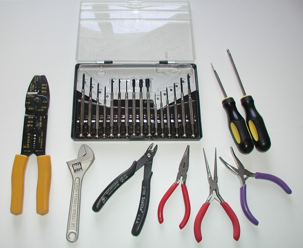
Your toolkit should contain a selection of Phillips and regular screwdrivers, mostly on the small side. Many hardware and “big box” home improvement stores sell kits of these. A basic toolkit should also have a set of miniature screwdrivers like those used by jewelers. These are essential for dealing with the tiny screws used with multipin connectors and with the terminals of many interface modules. At least one pair each of needle-nose pliers and diagonal cutters are essential for dealing with wires. A 6” adjustable wrench and a combination wire stripper and crimping tool would round out a very basic kit. These tools can often be found in prepackaged sets, and electronics-production-grade tools can be ordered from several online sources. Figure 6-1 shows a basic set of hand tools.
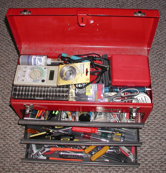
Of course, one could go all out and assemble a fully stocked toolkit. Figure 6-2 shows an overstuffed kit with a lot of miles on it. This would definitely be overkill for a one-time job, but if you have a consistent need for tools and odd small parts, a toolkit like this is essential.
Be kind to your tools
Never use a pair of pliers on things like nuts if you can avoid it. Pliers will usually slip and round off the edges of the nut that define its six-sided shape. It only takes a few moments of effort with pliers to make it impossible to remove a nut with even the correct tool, which is a wrench or a socket.
Also, try to avoid using something like the black-handled wire cutters shown in Figure 6-1 to cut heavy wire. The thin, sharp blades of the cutters can easily become nicked and render the tool useless. It’s also best not to use the cutters as wire strippers. Although this is possible with some practice, it is very difficult to control the amount of pressure sufficiently to avoid nicking the wire inside, or even cutting it. Damaged wires tend to break easily at the nick location. Use a wire-stripping tool for removing insulation. The large tool in Figure 6-1 with the lettering on it is a combination wire stripper, lug crimper, and screw cutter. For fine-gauge wire (in the 18- to 32-gauge range) consider the purchase of a dedicated wire-stripping tool with adjustable sizing. These range from just a few dollars to upwards of $100 or more for production-grade models, depending on the quality and features.
Where to purchase tools
Apart from the local hardware store, there are numerous places to purchase tools. Some of these are retailers specializing in discount tools imported from Asia, which you might also find in the “bargain bins” in some home improvement stores. Professional-grade tools are available from electronic supply houses and various distributors. In most cases there’s nothing wrong with the bargain-bin tools, but be careful to check for smooth operation, sharp blades, evenly machined surfaces, and sharp—not rounded—angles on the insides of sockets and the outside of hex wrenches.
Table 6-1 is just a representative sampling of possible sources for tools, and is in no way meant as an endorsement of any particular brand or distributor.
Source | Description | URL |
Allied Electronics | Online electronics components and tools distributor | |
Digi-Key Corporation | Online electronics components and tools distributor | |
Electronic Toolbox | Offers a variety of low-cost tools and supplies | |
MCM Electronics | Carries a range of parts, supplies, kits, and tools | |
RadioShack | Carries a good selection of tools and supplies online; availability varies from store to store | |
Stanley Supply and Services | Carries a range of tool brands for electronics | |
Techni-Tool | Supplier of tools and supplies to the electronics industry |
One of the best ways to get information about tools is to ask someone who has been working in the electronics industry for a while. Most technicians and engineers will have their favorites, and also some opinions about which tools they don’t like (and why). Spending some time online browsing websites is also a good way to get a feel for what is available and the price ranges one can expect.
Digital Multimeter
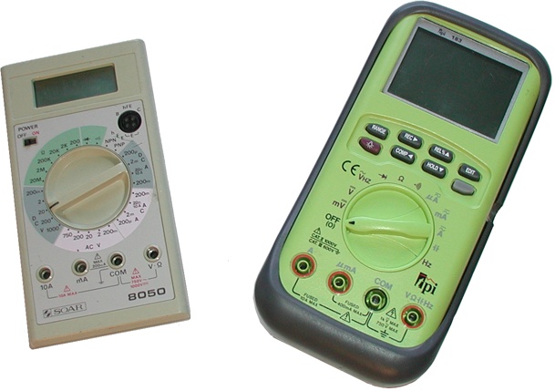
The modern digital multimeter has evolved over the years from its humble beginnings into a complex and capable instrument. Prices vary widely, depending on factors such as accuracy, ruggedness, and features. A simple and usable handheld DMM can be had for as low as $20, while some of the professional high-accuracy models can run to upwards of $500. Figure 6-3 shows both a low-cost model and a more expensive unit that includes an output port for data acquisition.
Both of the units shown can measure DC voltage, AC voltage, DC current, AC current, and resistance. The unit on the left in Figure 6-3 has a socket for testing small transistors, while the fancier instrument on the right has the ability to measure frequency and capacitance. It can also capture and hold a measurement. DMM instruments also come in bench models, like the one shown in Figure 6-4.
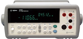
The high-end instruments can range to upwards of several thousand dollars in price, but they do offer accurate operation, high reliability, and a selection of data and control interfaces. We will be referring to instruments like the one shown in Figure 6-4 in Chapter 11, when we look at instruments with serial and GPIB interfaces.
With the high-end DMM units you also get a certificate of calibration, and most professional-grade instruments are calibrated periodically using a commercial or in-house calibration service. Unless what you will be doing involves requirements for high precision and repeatable measurements, this is not really necessary, although it is a good idea to occasionally cross-check one meter against another using the same voltage source and resistance reference.
DMM resolution
DMMs come in several different resolutions. In this case, resolution refers to the number of significant digits the meter will accurately display. Generally speaking, the higher the resolution, the more expensive the instrument will be.
Commonly available resolutions are 3½, 4½, and 5½ digits. The ½ refers to the last digit, which shows only 0 or 1. The basic resolution of a DMM is a function of the number of bits used in the analog-to-digital converter (ADC) inside the meter.
DMM usage tips
The following is a list of things to keep in mind when using a DMM:
When measuring voltages relative to ground, always connect the negative lead to ground first. If possible, connect it with a clip of some kind so it doesn’t come loose, and use only the positive lead to probe around. Remember that if the ground lead should come loose, the meter (and the unattached ground lead) will be at the same potential as whatever the positive lead is touching. This might not be a big deal when you’re working with low-voltage DC, but it can become a definite hazard when dealing with high voltages.
Be aware that the probe tips on the measurement leads can slip. If this happens on a live printed circuit board, the result can be catastrophic if the probe tip creates a short between the pins on a connector or an integrated circuit. A probe slip can also bring your hands into contact with potentially lethal voltages, which is another justification for clipping the ground lead and just using the positive lead to poke around. The old “keep one hand behind your back” rule applies when dealing with voltages that could injure or kill, such as AC wall voltage or high-voltage DC circuits.
Never measure resistance in a circuit of any kind with power applied. A meter set to a resistance measurement mode will usually not tolerate a voltage input for very long before something fails.
Never connect the meter to a voltage source greater than its rated maximum. Since most modern DMMs are capable of handling input voltages of up to 600 volts, this is usually not a problem. If you need to measure more than the meter’s maximum rating, consider purchasing a special high-voltage probe. Also remember that AC voltages are often given as the RMS value, not the peak value.
Always check the meter’s settings before attempting to take a measurement. Although almost every DMM has internal fuses on the inputs, it is still a very bad idea to try to measure a voltage when the meter is set to the current measurement mode. This is effectively a short between the positive and negative terminals (with a low-value series shunt resistor), and if one of the probes is connected to ground it can blow the meter’s fuse, damage its internal circuitry, or even damage the circuit being measured.
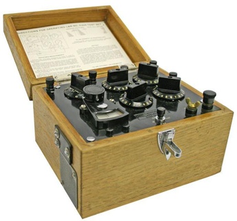
The meter leads have resistance. It is usually very low, on the order of 0.5 ohms or so, but if you are trying to measure something like a wire-wound power resistor with a low resistance (0.1 ohms, for example), the meter leads can contribute more to the reading than the part being measured. Some DMMs have the ability to compensate for the lead resistance, but with others you should measure the leads first and then subtract that from whatever the meter indicates. For things like current shunts, with resistances on the order of a few milliohms, one would typically use something like a Wheatstone or Carey Foster bridge to measure a very low resistance. As a historical footnote, Figure 6-5 shows a vintage bridge test set.
Soldering Tools
Soldering is the application of a molten low-temperature alloy to join two wires or make a connection between the leads of a component and the copper paths on a printed circuit board (among other uses). An alloy of tin and lead (typically 60% tin and 40% lead, although other formulations are available) was once the most commonly used solder, but with the recent push to move away from materials containing lead, new alloys are starting to appear. However, when one purchases solder for occasional use, the most readily available type is still tin-lead. It is relatively safe (the lead is bound to the tin in the alloy), and so long as one takes reasonable precautions it should not present a significant health hazard.
Solder for electrical use typically comes in the form of a very pliable thick silvery wire that also incorporates a hollow core filled with a rosin flux material. The flux melts and flows before the solder melts, and helps to remove oxidation from the solder and the surfaces being soldered. Some people prefer a paste flux, which is a thick, sticky brown paste that is supplied in small tins. It is applied to the pieces to be soldered before the actual soldering starts, and is also sometimes used in conjunction with flux-core solder wire to help make solid connections on printed circuit boards. A solder with a 60/40 composition melts at about 188°C.
Soldering irons come in a variety of sizes, temperatures, and prices. The low-cost models typically found at local electronics and hardware stores are around 15 watts and have small pencil-point tips. These can handle most small-gauge wires and circuit board work, and cost anywhere from $10 to $25. They are not, however, temperature-controlled, so the tip can sometimes get too hot, resulting in a weak solder joint or a burned circuit board. They also have a tendency to cool off rapidly when one is attempting to solder large objects or heavy-gauge wire. If you plan on doing more than just occasional soldering work, it is worthwhile to invest in a unit with temperature control and interchangeable tips. These can range in price from $50 to $300, depending on the wattage and the features included (operator-controlled temperature, digital temperature readout, internal grounding, and so on). Figure 6-6 shows a low-cost 15 W pencil-type soldering iron. You might also have noticed a similar unit in the top tray of the toolbox shown in Figure 6-2.
You will also need something to clean the tip and some way to hold the soldering iron when it’s not in use (just laying it down on the bench or table is generally not a good idea). Wire stands are available that include a small tray for a damp sponge to clean residue and oxidation from the tip. There are also tip cleaners in the form of small tins filled with a loosely coiled wire that require no water, and a paste-like material is available that will clean and brighten a soldering iron’s tip (it also comes in a small tin). Both are commonly used in electronics manufacturing, but they are not very common in the toolkit of the occasional user.
There are numerous resources available online that deal with solder, soldering irons, and how to solder. It is a good idea to get some scrap wire or a defunct printed circuit board and practice a bit before tackling a real project. Soldering may sound easy and look simple, but getting it right takes a degree of skill that only practice can provide.
Nice-to-Have Tools
In addition to the tools we’ve already discussed, there are some other tools that are incredibly useful, if not essential, for certain types of work. They aren’t used as frequently as the more common hand tools, but when they are needed there is really nothing that can do the work as well. Consider acquiring the following:
- Lineman’s pliers
These heavy, square-jawed pliers are designed to bend, twist, and cut heavy-gauge wires. They can also be used to bend thin strips of sheet metal, or cleanly break off pieces of plastic. Lineman’s pliers are available at most well-stocked hardware stores, and inexpensive imported versions can occasionally be found in bargain bins.
- Hex wrench set
Also sometimes called hex keys or Allen wrenches, these are simple tools with a hexagonal cross-section used to drive bolts and screws with a hexagonal socket in the head. These types of fasteners are commonly found in electronic devices and laboratory equipment, and there is nothing else that can deal with them. Hex wrenches also tend to be relatively inexpensive, and they are available in both SAE and metric sizes.
- Nut drivers
As the name implies, these tools are designed to handle nuts. They typically look like screwdrivers with a socket instead of a screwdriver tip, and some have a “T” handle to enable more torque to be applied to a nut. They are available in both SAE and metric sizes, and can be purchased as kits containing from four to eight or more tools in various sizes.
- Miniature socket set
Like nut drivers, sockets are designed to drive hex nuts and hex-head bolts, but they use a right-angle ratcheting handle to apply much more torque than is possible with a nut driver (too much, sometimes). Small, compact sets with a selection of sockets, a drive extension, and a ratchet handle are available in both SAE and metric sizes (often combined in the same set). These tools are intended for larger nuts and bolts, and typically range from 3/16” to 9/16” for SAE sizes, and from 4 mm to 14 mm for metric sizes.
Advanced Tools
There is a lot one can do with a tool like a DMM, but there are some things it simply cannot do. One application the DMM cannot handle is the direct measurement of electrical waveforms. Another is the visualization of logic signals on multiple parallel lines. For these situations, tools such as an oscilloscope and a logic analyzer can make the difference between knowing and just guessing.
The Oscilloscope
The oscilloscope is a very old instrument, and has been around in one form or another for at least 80 years (perhaps longer, depending on how one defines what an oscilloscope is). The reason for its success is its inherent usefulness for examining changing electrical signals over time. Early electronic oscilloscopes used vacuum tubes for signal amplification, and a specialized type of tube called an electrostatic cathode ray tube (CRT) for the primary display. An oscilloscope CRT is similar in operation to the CRT found in older computer monitors and television sets, except that it typically uses electrical fields rather than magnetic deflection fields to guide the beam onto the screen.
Modern oscilloscopes are digital instruments with LCD displays like those found in flat-screen monitors—the days of vacuum tube amplifiers are long past, and the CRT is quickly heading for obsolescence. Figure 6-7 shows the front panel of a simplified generic dual-trace digital oscilloscope.
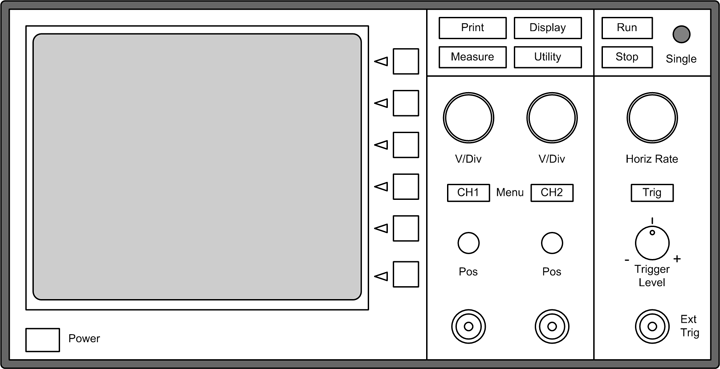
Dual-trace oscilloscopes with the ability to display two simultaneous signals are the most common, although single-trace instruments are available. Instruments capable of displaying four or more channels are also available. The latest high-end models provide color displays, advanced built-in signal processing and measurement capabilities, and network interfaces.
The vertical input channels amplify the input signals and cause the display point to move either up or down relative to a horizontal line defined as zero, or ground. The horizontal section of the instrument drives the display point across the screen from left to right, which is referred to as the horizontal sweep. A trigger circuit synchronizes the horizontal sweep with the incoming signal from either of the vertical channels in order to generate a waveform display that doesn’t “walk” or wander across the screen.
One fundamental characteristic of an oscilloscope is its bandwidth. Low-end instruments are usually limited to a 25 MHz bandwidth, meaning that they will start to attenuate signals above 25 MHz. This comes into play when a signal has harmonic components above its fundamental frequency. For example, if a 25 MHz signal is measured by a 25 MHz oscilloscope, it will probably display the fundamental waveform, but it will not accurately display harmonics above that, so some key features of the signal will not be shown. This can become an issue when examining square waves, which may contain higher-order components that are causing problems, as these will not appear on a slow oscilloscope. This is shown in Figure 6-8.
As a general rule of thumb, one should try to use an oscilloscope with a bandwidth at least four times the fundamental frequency of the signal of interest. If the only oscilloscope available has a bandwidth around the frequency of the fastest signal of interest, you should expect that there are probably things going on in the signals that you cannot see.
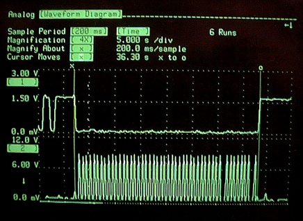
Figure 6-9 shows an image of a digital oscilloscope screen. This image shows two channels, one with a 0 to 3 V range and the second with a 0 to 12 V display range. Measurement cursors (the x and o symbols) are used to determine the time interval between the cursor locations, which in this case is 36.3 seconds. This particular instrument is an older model that uses a CRT display.
If you are not very familiar with oscilloscopes, then it is worthwhile to spend a little time and read up on how they work and how to use them. There are lots of excellent sources of information available online. The thing to remember is that an oscilloscope (and most other test instruments, for that matter) can only present data within the range of its capabilities, and attempting to interpolate missing data, or assuming that what is shown is completely accurate, can lead to erroneous conclusions.
Logic Analyzers
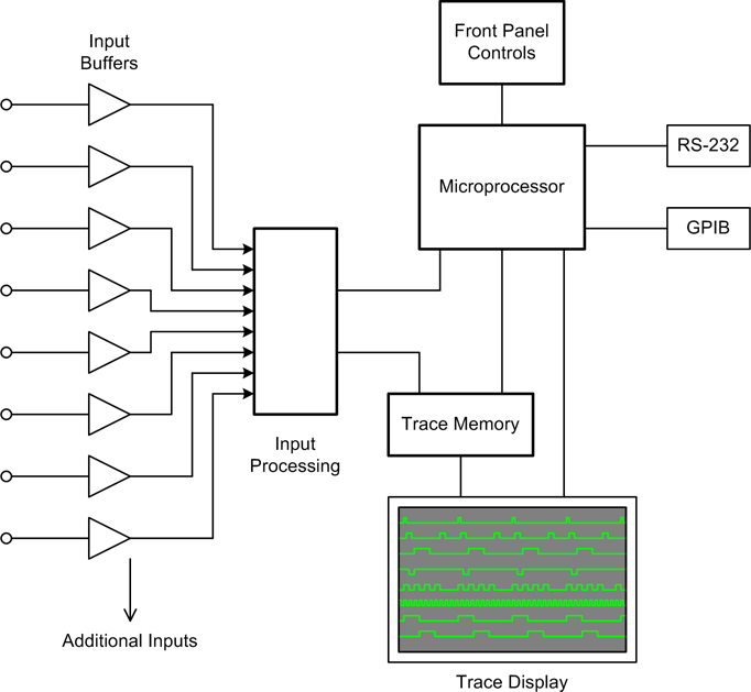
The logic analyzer is a very useful instrument for measuring and monitoring activity within digital circuits. Logic analyzers capture a set of digital inputs simultaneously and store the binary values in a short-term trace memory. The contents of the trace memory are then read out and displayed in the form of a timing diagram. We saw these types of diagrams in Chapter 2, and we will be seeing more of them in later sections.
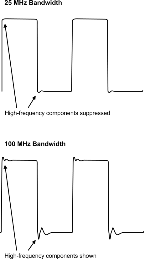
Figure 6-10 shows a block diagram of a simple logic analyzer. This diagram would be applicable to a self-contained instrument, but there are other ways to achieve a similar result. For example, if the signals are changing relatively slowly, one can use the parallel printer port on a PC as a simple four-channel logic analyzer (the PC parallel port has four input lines available).
One can also purchase inexpensive USB logic analyzer modules that use the PC’s display rather than providing one of their own. An example is shown in Figure 6-11.
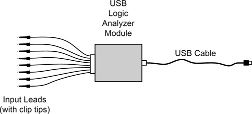
Prices and capabilities for USB logic analyzer modules vary, from about $150 to upward of $6,000. For most instrumentation applications, a low-cost unit will do all that is needed, as there really is no need to capture and display signals above about 50 MHz. Also, some models include features such as a serial protocol analyzer, which is handy for examining the data stream in a serial interface.
Test Equipment Caveats
The following are some key points to keep in mind when working with electronic test equipment:
As a general rule, never connect the ground lead of any AC line-powered oscilloscope, logic analyzer, or other instrument to the DC power in a circuit, unless that instrument is specifically designed with a so-called “floating ground.” The ground lead is for ground only and should always be connected to a ground point when attempting to take a measurement unless the instrument is specifically designed to allow the ground to “float.” If you just want to verify the presence of a voltage across two points, neither of which is at ground, use a DMM or a battery-powered handheld oscilloscope instead.
Always observe the maximum voltage ratings for an instrument’s inputs. Some instruments are limited to 25 V DC, while others can handle upwards of several hundred volts with the correct probe attached.
If you are using a digital oscilloscope or logic analyzer, be aware that there is a limit on the input frequency. If this limit is exceeded, the display will be “aliased” and show a (usually) distorted signal with a frequency that is lower than that actually present on the input. The manufacturer’s specifications should state the maximum measurable input frequency.
Supplies
Having a supply of items such as wire, wire nuts, electrical tape, and so on, readily available can make things a whole lot less frustrating and help to ensure that the end result will be both reliable and professional-looking. Table 6-2 shows a list of suggested supplies to keep handy.
Item | Description |
Insulated hookup wire | #22 stranded, various colors |
#20 stranded, various colors | |
#18 stranded, various colors | |
#16 stranded, various colors | |
Shielded coaxial cable | RG-58, 50 ohms impedance |
Wire nuts | Small (#18–14 size) |
Electrical tape | Black |
Kapton tape | 1/4″ wide |
Heat-shrink tubing | Various diameters (from 3/32 to 1/2″) |
Resistors | 1/4 watt; 100, 330, 1K, 2.2K, 4.7K, and 10K ohms |
Wire lugs | #18 to #16 wire gauge size |
Wire and cable typically come on spools in lengths from 10 feet to over 1,000 feet. For hookup wire, 25 feet is a good length, and a selection of standard colors (red, black, white, blue, and green) allows one to readily identify power (red), ground (black), and signal wires. Some types of wire, particularly in the smaller gauges, will have only a single copper conductor instead of multiple strands. Single-conductor wire is not recommended unless there is a specific reason to use it, as the single conductor can break if bent too far or nicked when the insulation is removed. Stranded wire is much more flexible and durable.
The Kapton tape mentioned in Table 6-2 deserves a brief explanation, as most folks outside of the aerospace and electronics production realms may not have heard of it. Basically, Kapton is a polyimide film with excellent temperature tolerance (–273 to +400°C). Among other applications, it is used to make flexible printed circuit boards, as insulation for wiring, as a protective wrap for the cable bundles on spacecraft, and as one of the outer layers of spacesuits. It is much better than electrical tape for many applications, as it leaves virtually no residue. It is also suitable for many uses in environments where low outgassing is a consideration (such as in vacuum chambers). Lastly, Kapton tape is a transparent golden color, which makes it useful for applying labels to already fabricated cabling.
Most of the supplies listed in Table 6-2 can be purchased from the suppliers listed in Table 6-1, with the possible exception of the Kapton tape. One place to purchase Kapton in small quantities is http://www.kaptontape.com.
New Versus Used
For most instrumentation projects, the demands placed on test equipment are very modest. Data sampling and control update intervals are relatively long (100 ms to many minutes), so having the latest expensive high-speed equipment really isn’t necessary. This means that the old oscilloscope that’s been gathering dust on the shelf in the storage room is probably more than adequate (assuming that it still works, of course).
It also means that there is no reason not to look into buying used test and instrumentation equipment. eBay is one possible source for used items, provided that you bear in mind that you should be prepared to unpack a broken or nonfunctional item when it arrives. This is a relatively rare occurrence, but it does happen.
Note
There is buyer protection available through PayPal (eBay’s preferred payment system) just in case your item does get drop-kicked somewhere in shipping, or doesn’t work as advertised, but there’s no way to recover the wasted time.
A local electronics store might also carry a selection of used or surplus equipment at discounted prices. The secret to putting older equipment to work is knowing what it will need to measure. For example, 100 MHz would be a reasonable lower limit for the bandwidth of an oscilloscope. A DMM should have at least enough digits to satisfy the accuracy requirements of the voltages you might want to measure in your system. While 3½ digits are usually acceptable for most purposes, 4½ digits are necessary for verifying the basic operation of an ADC or DAC.
Summary
You should now have some ideas for a shopping list of at least the basic tools you will need, and some idea of where to find them. We’ve also covered some of the basic electronics test equipment that you might need, and briefly discussed the pros and cons of buying new versus acquiring used tools and equipment.
Beyond the basic hand tools and a decent DMM, there isn’t much else you should need to get started, except perhaps some specialized tools for working with connectors.
Suggested Reading
If you would like to explore test equipment and measurement topics in more depth, I would suggest the following book as a good place to start:
- Electronic Test Instruments: Analog and Digital Measurements, 2nd ed. Robert A. Witte, Prentice Hall, 2002.
This book provides a solid introduction to basic measurement theory, followed by a very readable and informative survey of modern electronic test instruments and their applications. Each topic is supported with real-world examples drawn from the author’s own experiences.
You can also find appendixes in books on electronic circuit theory that describe the basic theory and applications of instruments such as DMMs and oscilloscopes.
Finally, many test equipment manufacturers offer excellent online tutorials for their products, so I would suggest that you look there first for more information when searching the Web.