
Sensors for automated food process control: an introduction
Abstract:
The measurement of process variables provides not only the means for monitoring and controlling a process, and hence for providing constant quality unaffected by the operator; it also can be key to reducing capital tied up in inventory and to using energy more efficiently. Parallel to this, the management of assets both at process and enterprise level is gaining in importance. This chapter reviews the requirements of the food industry on field instrumentation, the instruments available to measure process variables, and the integration of these instruments into automation systems. A few practical examples and an outlook on future developments complete the chapter.
3.1 Introduction
Food, like water, is an essential requirement of life. For many in the world who live where food is scarce, necessity overrules quality in the daily struggle for life. In the developed world, however, quality is a huge factor in determining what we buy. Quality, of course, lies in the eyes and taste buds of the consumer: for the greens among us in ‘organically grown’ fruit and vegetables, for the dietician in nutritional value, and for the greedy in the size of the portion. For the manufacturer, other criteria must be fulfilled to achieve basic quality. What no-one wants is snails in their lettuce and flies in their soup, or as far as processed food is concerned, hair, glass, metal, plasters, chemicals and bacteria in their tins or packages. And of course, akin to a Warhol painting, today’s tin of soup should taste like yesterday’s tin of soup, and tomorrow’s like today’s. It is not only the variety of processed food on the market available today that impresses but also the consistent quality with which it is produced.
A second factor in food choice is, of course, cost – not just for the consumer who likes to buy his food as reasonably as possible, but also for the supermarket where he buys. Faced with fierce competition from rival companies, price-cutting dictates the market. This in turn forces the food manufacturer to produce as cheaply and efficiently as possible, but without a loss of quality. Cost reduction is traditionally associated with an increase in automation and reduction of manpower within a production facility. Consistent quality has much to do with controlling processes. ‘First measure, then control’ is an old adage, but depending where it is applied along the supply chain, measurement brings additional benefits.
Food production facilities share a common infrastructure: inbound raw materials are stored ready for the production process; outbound products are stored before delivery. Here measurement of stock level, and concepts such as vendor-managed inventory, can lead to significant savings through reduction of stock to the minimum required for reliable production. The production process itself is often controlled by recipes to make products that frequently change. Then, the finished product must be bottled or packed, a procedure that requires an entirely different kind of control from that of the making of the product. Finally there are the so-called utilities: electricity, air, heat, cooling and water. Efficient use of energy has become a byword in manufacturing, and key to optimal use is measuring what is consumed.
3.2 Special considerations for food instrumentation
The processes involved in producing food find many parallels in other industries. Where they differ is that food is produced for eating and drinking by humans or animals: as a result, the product must be safe for consumption. For process instrumentation this leads to a number of special considerations with regard to its design and use.
3.2.1 Regulatory agencies
The food industry differs from many others in the extent to which the entire supply chain, from production to distribution, is monitored by government agencies. The industry itself has also set up its own watchdogs to assess advances in production engineering and make recommendations regarding good manufacturing practice. When choosing process instrumentation, therefore, it pays to check whether a corresponding approval or authorisation has been granted. Table 3.1 lists several bodies that are of particular importance to safe food manufacture.
Table 3.1
Regulatory and standardisation authorities
| Body | Field of activity |
| 3-A sanitary standards | American standards service with a long history of producing hygienic standards for the dairy industry. Also tests and authorises process instrumentation regarding its fitness for use in food production. 3-A standards are binding in the USA, but nowadays have less impact worldwide. |
| European Hygienic Equipment Design Group | Formed in 1989 with the primary aim of the safe manufacture of food products, is supported by research institutes, equipment manufacturers and end users. Issues guidelines on hygiene, tests and certifies equipment and publicises state-of-the-art technologies. An EHEDG approval means that the equipment has been successfully tested with respect to its suitability for food applications. |
| International Dairy Federation | Responsible for standards and recommendations in the dairy industry which are often published as ISO standards. |
| US Food and Drug Administration | US government agency charged with ensuring the safety of food production. Issues licences for products, whereby the processes, constituents, materials and constructional details are subject to examination. The use of an FDA-approved material is a guarantee that the component concerned will not be attacked by the food product. |
| EU and national governmental agencies | Play a similar role to the FDA in the European Union or the country to which they belong. Lay down the permissible levels of trace organic and inorganic substances in food products. Since this is an area of permanent research, it is possible that regulations vary from country to country. |
| Retail organisations: IFS, GFSI, BRC, SQF, ISO 22 000 | Retail associations, certification bodies and quality standards set up to ensure the quality of food in supermarkets and other retail outlets by auditing their suppliers. Although not the primary focus, good manufacturing practice and correctly installed technology are factors in certification. |
The prime aim is to ensure the safety of a product, thus protecting consumers from exposure to, for example, chemical contaminants and toxins, bacteria or foreign bodies. Once identified as such, a defective product has to be removed from the market immediately, demanding high levels of traceability at all stages of production. As far as instrumentation is concerned, the effect of regulation is twofold. On the one hand, the regulations dictate how and of what materials a measuring device may be constructed, on the other, their measurements help fulfil the regulations by providing the information necessary to control and monitor the process.
3.2.2 Wetted parts
A well-designed instrument for use in the food industry must take three factors into consideration: how does the device behave in normal operation, what happens if a component part becomes mechanically defective and how can it be cleaned and sterilised. The so-called wetted parts, that is, those parts of the instrument in direct contact with the material being measured, are the most critical in both respects. Even non-contact devices must be considered to have wetted parts when they intrude into a vessel. Although they are not directly in contact with the medium, they may have crevices in which food can gather and rot, or be exposed to high temperatures or vapours that release unwanted substances.
Taking the three cardinal sins, chemical contamination, bacteria and foreign bodies as criteria, each wetted part must be checked to see whether it poses a hazard. Chemical contamination may be caused by migration, wear and tear of a moving part, abrasion by flowing material, leakage into the process or simply by choosing the wrong material for the foodstuff being processed. It is important to remember that, even if we do eat them, foods are nothing more than mixtures of organic and inorganic chemicals, which may be acid or alkaline and which may react with the materials with which they are in contact.
To avoid chemical contamination through the wrong choice of material, it is important that instrument manufacturers use substances considered safe for food production. To this end, the Food and Drug Administration of the United States of America (FDA) maintains a list of Food Contact Substances (FCS) (FDA, 2010). A similar document for metals is Guidelines on Metals and Alloys used as Food Contact Materials (Council of Europe, 2002), and for stainless steels the Sheffield Corrosion Handbook (Avesta, 1994). Most instruments used in food production are made of steel grades 1.4301/304 (18% Cr, 10% Ni) or 316 (17% Cr, 12% Ni + Mo), although other alloys or titanium may be used. Table 3.2 lists the properties of various stainless steels used in food production.
Table 3.2
Various stainless steels suitable for the food industry

*The AISI steels are equivalents but do not have identical compositions.
A number of factors may help decrease the risk of bacterial contamination. Regular cleaning and gap-free design reduces the broad risk of infection, but the proper material, design and finishing of the wetted parts is just as important. Dead ends should be avoided since they are harder, if not impossible, to clean. In addition to product wastage, they mean longer phase shifts with more flushing water, longer heating times for cleaning, and a huge heat demand for steam sterilisation. Wetted parts must exhibit a high degree of corrosion resistance, both against foodstuffs with which they are in contact as well as the agents used to clean and sterilise them. In addition, high temperatures, strong vibration and mechanical stress may enhance the risk of electrochemical and intergranular corrosion of stainless steel. The one results in surface pitting, providing an ideal breeding place for bacteria, the other in the depletion of the nickel and chromium at the grain boundaries, which means a component will rust.
Design factors that reduce the risk of bacterial contamination are streamlined contours, clean welding, no nooks and crannies, and no obstructions that might cause the product to gather and rot. It is also standard practice that wetted stainless steel parts are electrically or mechanically polished. A surface roughness Ra ≤ 0.8 μm/150 grit is regarded as safe but, for certain process connections, even lower values are normal. Polishing has the double effect of reducing susceptibility to surface pitting and preventing products from sticking.
The introduction of foreign bodies happens more by accident than design, but good risk analysis can mitigate the effects, should the accident happen. What could be the causes of failure, and what happens when a component fails? Are flowing gases, liquids or solids causing abrasion or generating high mechanical forces that, combined with high temperature or vibration, are increasing electrochemical attack or mechanical fatigue? Is the back pressure of a flow meter high enough to prevent liquids from boiling and causing cavitation? Has a thermowell been designed to withstand the pressures to which it is subject? Does its position within a pipe subject it to more than the design forces? Are instruments able to withstand the forces and temperatures generated during external cleaning or cleaning-in-place? What happens if the diaphragm of a pressure transmitter is ruptured? Is the fill fluid FDA approved – does its release mean that the entire batch must be thrown away? These and many other criteria should be assessed when choosing a measuring instrument.
It is the result of such considerations that pressure transmitters with metal diaphragms, rather than ceramic measuring cells, are used in direct contact with food. Mercury-in-glass thermometers are actually proscribed by FDA Rule 21 CFR Part 113 for low-acid canned-food retorts, but here concerns by the manufacturers about mercury spills have lead the FDA to propose a rule change allowing equivalent electronic devices to be used instead. In food filling applications, there is a definite trend towards replacing older mechanical piston and cup fillers by electromagnetic and Coriolis flowmeters. Here wear and tear, maintenance, as well as measurement accuracy, are the driving factors for refurbishment.
3.2.3 Process connections
A process connection is the means by which an instrument is installed in a pipe or vessel that contains the process material to be measured. Ideally, it should offer the product no possibility to become entrapped. One way to do this is to weld the instrument connection in place and then grind and polish the weld. This is, of course, not practical for small pipe diameters and replacement is difficult, should the instrument fail. Nevertheless welding is often encountered for thermowells, where the sensor insert is easily replaced, as well as for some types of flowmeter.
The majority of instruments in food processing, however, are installed by means of so-called sanitary couplings. These provide gap-free connection and are designed to be easily dismounted, allowing instruments and pipes to be quickly removed for cleaning. The couplings themselves are normally held together with clamps or external screw unions. Over the years a number of different designs have come onto the market, a selection of which are summarised in Table 3.3. Manufacturers also offer special adapters for mounting instruments on tanks and ports for the insertion of, for example, pH sensors into tanks and pipes. Here it is important that these have a sanitary approval issued by the European Hygienic Equipment Design Group (EHEDG) or similar body.
Table 3.3
Sanitary couplings for the food industry
| Type | Use | Description |
| Dairy coupling to DIN 11851 | Pipes and tanks | Low cost coupling with threaded boss and slotted sleeve. It does not allow flush mounting and is no longer considered to be hygienic; however, a special gasket set can be purchased which brings the coupling up to standard. |
| Aseptic screwed, flange (DRD) and clamp unions to DIN 11864-1, DIN 11864-2 and DIN 11864-3 | Pipes and tanks | Designed to EHEDG recommendations, as a replacement for the dairy coupling, these unions offer better hygiene thanks to a flush sealing construction. The mechanical coupling is via threaded sleeve, bolts or clamp, the seal being flush with the pipe wall. Can be used for in-line and insertion instruments. |
| Varivent® coupling | Pipes | In-line housing that allows the flush mounting of a sensor, which is attached to the housing by means of a screw clamp. Three housing types cover a wide range of pipe diameters. A tank adapter is also available. |
| APV coupling | Pipes | In-line housing of similar construction to the Varivent coupling. The sensor, however, is bolted in position. |
| SMS coupling | Pipes and tanks | Low cost, Scandinavian standardised screw coupling to SMS 195346. Its weakness lies in the hygienic adaptation to the process, which does not allow flush mounting, and for this reason it is no longer considered to comply with modern hygienic standards. |
| IDF coupling | Pipes and tanks | International Dairy Federation (IDF) screw coupling standardised in ISO 2853 |
| Tri-clamp® coupling | Pipes and tanks | Sanitary coupling with bevel seating produced by the Tri-Clover Company in America. Instruments are quickly mounted and fixed with snap-on clamps. The couplings find widespread use in America. |
3.2.4 Instrument housings
Depending upon the design of the instrument, a housing may contain only the connecting terminals, for example, as for a temperature probe, or the entire transmitter electronics. In both cases it must provide adequate protection against the ingress of moisture or dust and, when the instrument is used in an explosive risk area, the egress of a spark or flame. The former is governed by the degree of protection provided by the housing, the latter by a suitable type of protection provided by the housing or the instrument output circuit.
As far as the ingress of moisture and dust is concerned, there are two major classification systems, IP ratings (IEC, 2001) and NEMA ratings (NEMA, 2008). Tables 3.4 and 3.5 explain the meaning of each rating type. It is usual that manufacturers quote both in their technical specifications. In the IP standard, the degree of protection is indicated by a two-part code. The first number is concerned with the protection from the ingress of solid matter, the second with water: the higher the number, the better the protection against dust, water jets or submersion. In order to withstand the frequent cleaning in a food production facility, housings with ratings of IP 65 or better are required. The NEMA standard comprises 14 type codes that deal with practical requirements on housings suitable for indoor and outdoor use. It also makes a statement about the protection from external influences and conditions such as mechanical impact, corrosion, humidity, mould, pests, dust, etc. A NEMA 4X enclosure is best suited to the requirements of the food industry.


Explosion protection is not a major issue in the production of food. If flammable liquids or easily ignitable gases are present, for instance in the distillation of spirits, then instrumentation must be approved for use in explosion-hazardous areas. Powders can also be a problem, since clouds of dust are easily combustible under certain conditions. For milling, storage, conveyance and bagging operations, therefore, the Dust-Ex equipment should be used.
Although suitable types of protection have long been agreed, until recently Europe and North America had their own nomenclature for classifying a hazardous area. The situation has been eased by the latest IEC standard, which has also been adopted by North America. Table 3.6 lists and explains the types of protection of interest to food processing. Readers wanting a fuller explanation of explosion protection are referred the booklet ‘Basics of Explosion Protection’ (Stahl, 2007).
Table 3.6
Types of protection for gas and dust (D) atmospheres
| Type of protection | Standard | Significance |
| Flameproof enclosure ‘d’ Protected by enclosure ‘tD’ | IEC 60079-1 IEC 61241-1 | The enclosure (housing) is designed such that any spark or explosion is retained within it. Frequently met in America where the entire cabling is routed in conduits. Also used in Europe for Dust-Ex protection and system components. |
| Increased safety ‘e’ | IEC 60079-7 | Electronics are designed such that high temperatures and sparking cannot occur during normal operation. This type of protection is met e.g. in 4-wire devices and power supplies. |
| Intrinsic safety ‘i’ Intrinsic safety ‘iD’ | IEC 60079-11 IEC 61241-11 | Protection is achieved by limiting the current flowing in the device signal circuits. Restrictions apply to installation and cables used. Favoured method for European installations. |
| Type of protection ‘n’ | IEC 60079-15 | Device is designed so that, under normal and defined abnormal operating conditions, it cannot ignite a surrounding explosive atmosphere. Used for all Zone 2 electrical equipment. |
| Encapsulated ‘m’ Encapsulated ‘mD’ | IEC 60079-18 IEC 61241-18 | The entire electronics of the device are potted, so that no spark can enter the surrounding atmosphere. |
3.3 Measurement methods
In order to ensure consistent quality and economic production of food, the underlying processes must be controlled. This means in turn that the variables affecting the process, for example, temperature, or the parameters indicating a certain quality level, for example, specific gravity, must be measured. Normally in process control it is sufficient to measure the variables pressure, temperature, flow and level. Variables such as pH, turbidity, viscosity and density give an insight into the quality of a product. There are other important quantities, however, that are not covered in this chapter. Trace moisture and humidity sensors play an important role in storage and conditioning of products such as stored fruit, meat or other raw materials. The reader interested in humidity measurement methods is referred to other literature on the subject (Bentley, 1998).
Readers wanting a more comprehensive overview of the instrumentation available to measure pressure, temperature, flow and level are referred to ‘Instrumentation and sensors for the food industry’ (Berrie, 2001). This chapter restricts itself primarily to electrical instruments that are easily integrated into control and plant asset-management systems.
3.3.1 Pressure
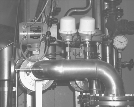
In food processing, the main applications for pressure measurements are in piping, across filters, as well as in closed tanks. Figure 3.1 shows a typical application. The toughest conditions are to be found in piping, where instruments must be designed to withstand overload pressures far beyond their normal operating range. Pumping action and opening and closing of valves causes surges in pressure up to the maximum operating pressure of the pump. High pressure peaks are also generated if a valve closes abruptly – a particular problem in the low-pressure region. Pressure instruments must also be immune to vibration and be able to withstand the temperatures and stresses induced by internal and external cleaning.

Pressure instruments may measure absolute, gauge and differential pressure:
• Absolute pressure devices measure the actual pressure acting on the sensor, displaying approximately 1000 millibar for atmospheric pressure.
• Gauge-pressure devices measure the pressure relative to atmospheric pressure, displaying approximately 0 millibar for atmospheric pressure – lower pressures are output as negative values.
• Differential pressure devices measure the pressure difference between two tapping points, for example, in a pipeline or a tank. They are usually used to measure level and, in connection with a primary element, flow.
There are three basic types of pressure-measuring instrument: manometers, mechanical pressure gauges and electrical pressure transmitters. Of these, electrical transmitters are most suited to automation, although the other types are still encountered in many plants.
Electrical pressure transmitters
Electrical pressure transmitters output a standardised signal that represents the quantity being measured, for example a 4–20 mA current signal, or a measured value transmitted over a digital communication interface. Most electrical pressure transmitters use a flexible, ceramic or metallic diaphragm as the pressure-sensing element, which forms the front isolating element of a sensing chamber. By using the appropriate process connection, it is possible to produce flush-mounted pressure devices that have no cavities and that are easy to clean.
In general there are three measurement principles: resistive, capacitive and inductive. The design of the cells depends on the manufacturer and measurement principle used. Pressure can also be measured by the resonance-wire or vibrating-beam method, whereby the shift in resonance frequency or change in vibration frequency is proportional to the pressure acting on the sensing element.
Table 3.7 summarises typical operating conditions for pressure-measuring instruments. No accuracies are included, since they depend on the individual transmitter. Most data sheets quote the measured error, the hysteresis and reproducibility measured at a reference temperature, usually 20 °C although sometimes other ‘overall’ accuracies are given. The temperature effect, which indicates by how much the accuracy changes for a given temperature rise, is an important factor in pressure measurement. Depending on the fill fluid, which is required when the sensor is operating with a diaphragm seal (an extension which allows flush mounting) or a remote seal and capillaries, this can be quite large. The overload pressure indicates the ability of a device to withstand pressure peaks without mechanical damage to the sensor (a recalibration may be necessary).

3.3.2 Temperature
Monitoring and control of temperature is an important factor in assuring the quality of the end product. For example, a wrong temperature during the manufacture of dairy products seriously affects their shelf life, while the wrong temperature in a retort for producing canned foods may result in bacterial contamination. In pasteurisation, freeze drying and similar processes, temperature control is essential if the quality and safety of the product are to be guaranteed. Any unaccountable rise in temperature in a storage silo may be the first indication that the raw material in store is deteriorating. Temperature is also measured in utility applications, for example in refrigeration, steam heating or cleaning-in-place (CIP) plant, see Fig. 3.2 . The temperatures to be recorded range from about − 50 °C (− 58 °F) in cold storage to + 150 °C (+ 302 °F) in sterilisation-in-place (SIP) applications. Only in steam generation will higher temperatures up to + 250 °C (482 °F) be found. Accuracy, depending on application typically ± 1 °C or better, is very important, and of course, hygiene is essential where there is contact with food.
Measurement principles
Temperature can be determined by measuring one of three quantities on which it has an effect: force, electricity and radiation. Radiation is the phenomenon used by pyrometers, and since they are mainly used in high-temperature applications, for example, in furnaces, they will not be considered further. Force-type temperature devices include bimetallic strips, which may be used as continuously-reading gauges or switching devices, as well as filled thermal systems, that is, thermometers. Mercury-in-glass thermometers are still proscribed for certain applications by the FDA, see Section 3.2.1, but in these cases, a second temperature sensor can be installed for control. Otherwise their use today is limited to optical back-up of electrical systems.
Electrical temperature devices
Electrical temperature devices use the temperature dependency of electrical properties of particular materials to provide a measurement. There are four different types: semiconductors, resistance temperature detectors (RTD), thermocouples and silicon resistors, although only RTDs and thermocouples are of real interest in the production of food.
RTDs, also known as resistance thermometers, comprise a thin-film or wire resistor with a standard resistance of 100 Ω, 500 Ω or 1000 Ω. The resistor material may be platinum or nickel, the standardised designations being Pt100, Pt500, Pt1000 or Ni100. The sensors are very stable, have a wide operating range from example − 200 °C to + 850 °C (− 358 °C to + 1562 °C) depending upon type, and exhibit a well defined relationship between resistance and temperature. The dependencies are specified in a number of international standards (IEC, 2008). RTDs conform to one of two standardised accuracy classes: Class A = 0.15 °C + 0.002 (t°C); Class B = 0.30 °C + 0.005 (t°C); where (t) is the unsigned numerical value of the temperature in °C. Higher accuracies are also available.
RTDs often have a relatively slow time response and produce only a small change in resistance per unit increase in temperature. To limit or avoid errors where sensing element and evaluating electronics are separated by some distance, 3-wire or even 4-wire connections are used. RTDs are also sensitive to vibration and shock, so that care must be taken in their design.
A thermocouple (TC) comprises two wires of different metal joined together at their ends. If the two junctions are at different temperatures, a potential difference is created that causes a current to flow around the loop. If one of the junctions is kept at a constant temperature, the magnitude of the current that flows is a measure of the temperature at the other.
TCs have a wide operating temperature range: depending upon type and conductor diameter, they can measure up to + 1800 °C (+ 3472 °F) and are standardised (IEC, 1995). They usually have a faster response than RTDs, but are less accurate (± 0.5 °C to ± 1.5 °C for IEC 60584 Class 1, depending on type). In Europe they are usually only used in preference to RTDs for temperatures above 600 °C. In America, however, they are being increasingly used for lower temperature ranges where accuracy is not a major factor in measurement. TCs are simple, rugged, and inexpensive and require no external power supply. On the other hand, the signal is non-linear, they exhibit low sensitivity, and have relatively low stability. A reference junction is required and they must be compensated. Moreover, metallurgical changes and ageing sometimes causes a loss of performance. A more serious problem is that the low voltage output is susceptible to electromagnetic interference.
Although a complete temperature transmitter with thermowell can be purchased from most manufacturers, many users prefer to buy the various components from different suppliers. Figure 3.3 shows schematically a typical temperature assembly:
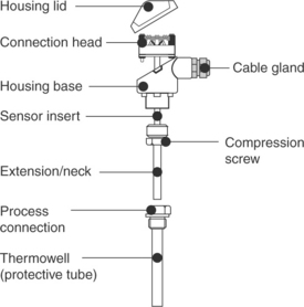
Fig. 3.3 Components of a temperature-measuring assembly, showing a sensor insert with terminal connections.
• The sensor insert is the heart of the assembly. It comprises a metal sheath containing the sensing element and connection wires. The connection terminals normally cater for 2-wire, 3-wire and 4-wire connection.
• The housing protects the sensor insert, the terminals and, where appropriate, the head transmitter from the ingress of water and dust. Many housing designs are standardised.
• The thermowell may be separate or an integral part of the temperature assembly and provides the contact with the medium. It is designed for a particular medium and range of flow rates and must be used as described in the appropriate standard or data sheet.
• For high-temperature applications, an extension (or neck) is inserted between the housing and thermowell.
To reduce mechanical load when thermowells are mounted in pipes, a position or orientation should be chosen that reduces the surface area facing the direction of flow. In addition, a thermowell must be covered with medium at all times when the signal is required. Since the thermowell produces turbulence in the downstream flow, care should be taken that it is not positioned too closely to any other instrumentation in the pipe. In tanks, there is usually space for vertical or horizontal mounting. Care should be taken not to position it too close to moving parts such as agitators, pumps or valves, since the forces generated by the movement of fluid may exceed the mechanical strength of the thermowell or lead to increased abrasion or corrosion.
3.3.3 Flow
Flow is an important control variable that also delivers quantity information to the plant operator. There are many methods of measuring flow, and selection can be difficult. It must take into account not only the physical properties of the medium to be measured but also the required accuracy, line size, environment, purchase costs and installation. With the exception of clamp-on ultrasonic instruments, all flowmeters are installed in-line, so hygiene is also an important factor. The sensing element must be able to withstand the temperatures met in CIP or SIP procedures, which most hygienic versions do, or if the instrument cannot be cleaned in situ, it must be easily dismantled to facilitate cleaning.
Fluids with high viscosity or containing entrained solids call for non-obstructive measurement. If fluids solidify at relatively high temperature, as is the case for hydrogenised oils, or are sticky, as are chocolate and sugar syrup, the flowmeter must be heated. Condensation might be a problem when the product is chilled: in this case a remote housing, which can be mounted at some distance from the measuring point, must be selected. Mechanical flowmeters are seldom used in hygienic processes nowadays, but two mechanical flowmeters, positive displacement and turbine, are still encountered in older plant. A description can be found in ‘Instrumentation and sensors for the food industry’ (Berrie, 2001).
Table 3.8 indicates the areas of application of each measuring principle covered in this chapter. For the purposes of flow measurement a conductive liquid has a conductivity ≥ 5 μS/cm for externally powered flowmeters, ≥ 50 μS/cm for loop-powered devices. Examples of conductive liquids are well water, fruit juices, yoghurt, milk, beer in addition to acids, alkalis and water-based emulsions. Nonconductive liquids are fuel oils, organic solvents, liquid sugar and demineralised water.
Table 3.8
Areas of application of electrical flowmeters
| Measurement principle | Application |
| Electromagnetic | Electrically conductive liquids (> 5 μS/cm) with or without solids, e.g. water, wastewater, sludge, slurries, pastes, acids, alkalis, juices, fruit pulp, etc. |
| Coriolis | Virtually all fluids: cleaning agents and solvents, fuels, vegetable oils, animal fats, alcohol, fruit solutions, vinegar, ketchup, mayonnaise, gases, etc. Mass flow, density and temperature (the primary measured variables) can be used to derive other variables such as volume flow, solid contents, concentrations, and complex density functions. Viscosity can also be measured. |
| Vortex | Volume flow of liquids, gases and steam. |
| Ultrasonic | Volume flow of any liquid, regardless of electrical conductivity. |
| Differential pressure | Flow measurement of gases, steam and liquids. |
| Thermal mass | Mass flow of gases. |
Electrical flowmeters
Electromagnetic flowmeters use the voltage induced by a conductive liquid flowing through a magnetic field to measure volume flow (Faraday’s law of electromagnetic induction). The induced voltage is proportional to the flow rate and independent of changes in fluid density, viscosity and pressure.
As the flowmeter is essentially a straight pipe, not only beer, water and milk can be measured, but also products such as yoghurt, molasses (when conductive) or rice pudding, which could loose their constitution if forced through a restriction. The flowmeter is suitable for a variety of applications, for example flow control, custody transfer and high-speed filling. Figure 3.4 shows two electromagnetic flowmeters installed in a brewery.

Electromagnetic flowmeters have a general installation requirement of only 3–5 straight pipe diameters upstream of the measuring point. They operate best in a turbulent flow regime. If used to monitor high viscosity products in a laminar (plug flow) or transitional flow regime, the absolute accuracy of the meter may suffer.
Coriolis mass flowmeters use the frequency shift caused by a flow of liquid through two metering tubes oscillating at their natural frequency to measure mass flow. Since the natural frequency is directly related to the mass of fluid in the tubes, it is also possible to measure density. The tube temperature is also monitored to compensate for density and single-tube flowmeters can be used to measure viscosity. This versatility combined with high accuracy makes the Coriolis mass flowmeter a very valuable measurement device. The straight tube design is ideal for the food industry, provided titanium is an acceptable material.
Coriolis flowmeters find use in continuous blending, filling and process monitoring applications, particularly when the mixing is controlled by density or the final product is to be sold by weight. Their high accuracy makes them suitable for dosing flavours and similar food additives. They measure viscous media and compound products such as soup, chocolate, honey and mayonnaise. There is no requirement for up- and down-stream lengths and the devices operate independently of changing fluid properties. Figure 3.5 shows a bank of Coriolis flowmeters specially designed for dosing applications on a filling machine.
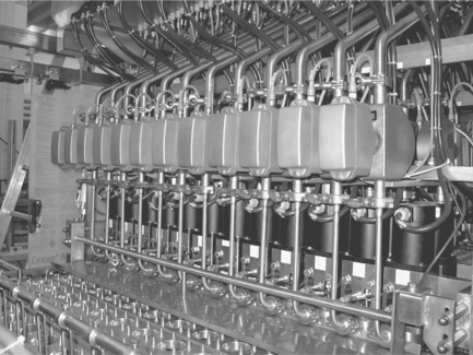
Fig. 3.5 Coriolis flowmeters installed on a filling machine. (Source: Courtesy of Endress + Hauser.)
Vortex flowmeters measure flow velocity by counting the number of vortices shed per second from a bluff body (Karman vortex street). The vortices are detected by sensing the vibration of the bluff body caused when they are shed. A correctly sized meter provides a linear output, low pressure loss and high accuracy over a wide flow range for low viscosity liquids, steam and gas. When the minimum specified flow rate is reached, however, the device will cut off, that is, the output drops to zero.
Modern vortex meters are cost-effective in providing instantaneous flow rate and totalised flow. The device has no moving parts, and inserts directly into the pipeline, making installation and cleaning-in-place straightforward, although it is not suitable for hygienic applications. Increasing numbers are to be found in utility applications, however, particularly for steam-flow measurement.
Ultrasonic flowmeters measure flow by either the Doppler method or the time-of-flight (TOF) method. In the Doppler method, the change in frequency that occurs when an ultrasonic pulse is reflected by a bubble or particle provides a measure the velocity of a flowing medium. In the TOF method the difference in the time of propagation between a pulse travelling with and against the flow provides the same information. Doppler flowmeters are seldom found in the food industry.
TOF ultrasonic flowmeters may be in-line, clamp-on, or the sensors may be inserted into the piping. Accuracy is low in standard applications, but can be increased by using additional sensors to form a multiple path. In this configuration, unsymmetrical and laminar flows can be measured. They are suitable for fluids with very little or no solid content, highly viscous fluids and very low flow rates. Their flexibility makes them useful for trouble-shooting and commissioning.
Differential pressure flowmeters measure the pressure drop across a restriction in a pipe, which is proportional to the square root of the fluid velocity (Bernoulli’s law). The restriction is the so-called primary element. A wide variety of primary elements exist, but by far the most common is the orifice plate. The range of a differential pressure flowmeter depends upon the size of the orifice. Turndowns of maximum 4:1 are possible. Wear of the orifice edge will reduce the meter’s absolute accuracy over time, so regular calibration is necessary.
The food industry uses differential pressure measurement almost exclusively for flow measurement in service systems, for example, steam or compressed air lines. The overriding factors here are the high operating pressures and temperatures that can be encountered. The technique is popular because of its robustness and simplicity, combined with a wealth of independent data surrounding operation and installation.
Thermal mass flowmeters use the heat-convection effect of a moving fluid to measure mass flow. They are normally used for dry-gas measurement, having a wide turndown, up to 100:1, and negligible pressure loss. Mass flow rate is measured directly without need for additional temperature or pressure compensation. In the food industry, they can be used in utility and process gas measurement, including CO2 distribution, nitrogen gas distribution and purge flows, natural gas metering and compressed air. The thermal properties of the gas must be taken into account when specifying the meter. As they can detect extremely low flows, they are also suitable for leak detection.
Bulk solid flowmeters
There are many applications in the food industry which involve monitoring the transportation of bulk solids to various parts of the plant, for instance coffee beans, salt, potatoes, tea, cereals, fruit and vegetables. The requirement ranges from simple switches to determine that a product is no longer falling from a conveyor belt, to a continuous measurement, for example, the flow of crisps to a flavour drum, to ensure the correct ratio of the flavouring.
Microwave barriers, for example, signal either the presence of absence of product between their transmitter and receiver units. A Gunn diode can be used to determine whether a product is moving or not. For continuous measurement, impact plate weighers can be used. Here free-flowing product falls onto a sensing plate that measures its bulk flow. The fall height must be at least 800 mm, and the measuring range is from 30 to 120 kg/h. The alternative is to use a load cell mounted under a conveyer belt. After calibration, such systems are capable of accuracies of 0.25–2%, depending upon design.
3.3.4 Level
The primary application of level measurement in the food industry is to monitor contents of storage or process tanks and silos containing raw, intermediate and finished products. In process control, continuous measurements are used to control the filling and emptying of tanks, retorts, reactors, etc. Prevention of overspill and dry running of pumps are typical applications where level switches are used. Table 3.9 lists the level-measuring instruments normally used in food processing. With the exception of ultrasonic transmitters, all are available in hygienic versions.
Table 3.9
Properties of level transmitters used in the food industry. Values are guidelines only: for specific values see the manufacturer’s data sheet

Capacitance level transmitters use the capacitance between the sensing element, a rope or rod, and the tank walls, as a measure of product level. Depending upon design, they may be used for both continuous level measurement and level-limit detection of both conductive liquids and electrically non-conductive materials. For non-conducting liquids, measurement is dependent upon the dielectric constant, and the transmitter must be recalibrated on a change of product. Depending upon the transmitter, it may be possible to self-calibrate by comparing the reading with a point measurement. Bulk solids with grain size up to 30 mm can also be measured. Current applications are restricted to limit detection. The method is suitable for pressures up to 100 bar and in the temperature range − 80 °C to + 400 °C (− 112 °F to + 752 °F). It is also insensitive to pressure surges caused by, for example, stirrers. Since capacitance transmitters offer a fast response they are particularly suitable for small vessels, for example, for dosing and filling machines.
Conductance level switches are used for limit detection in conductive liquids. The sensing element comprises a stainless steel rod that is mounted in the top or the side wall of the vessel. The switching position is determined by the length or the mounting point of the sensor respectively. There is a sudden drop in resistance (or rise in current) when liquid comes into contact with the sensing element signalling that the limit level has been reached. The signal is be used to switch a relay, NPN- or PNP-transistor, or to provide a switching signal to a remote transmitter. The probes are essentially the same as capacitance probes. The operating conditions are also the same, whereby a change in the conductivity of the liquid has no effect on the switching.
Hydrostatic level transmitters measure the pressure exerted by a head of liquid, which is proportional to its height. Measurements are made with specially designed differential-pressure or gauge-pressure transmitters. The measurement is dependent on the density, but this can either be entered as a calibration parameter or eliminated by calibrating at the desired empty and full levels. In the case of an open vessel, where atmospheric pressure is acting on the head of liquid, only one measuring point at the bottom of the tank is required, see Fig. 3.6 .

Fig. 3.6 Hydrostatic level measurement on a beer-fermentation tank. (Source: Courtesy of Endress + Hauser.)
If the vessel is closed, an additional measurement of head pressure is required. The difference between the two measurements gives the level. For differential pressure transmitters, the level is displayed directly, but the fill fluid in the capillary to the head-pressure measuring point may produce an unfavourable temperature effect. If two gauge-pressure transmitters are used, the head pressure is available for control and the level is normally calculated by the controller. In the case of fieldbus devices, the value can be downloaded for display at the lower device.
Hydrostatic pressure transmitters are the most used level measurement technology in the food industry. They operate continuously at temperatures up to + 100 °C (+ 212 °F), are insensitive to build up of product and will withstand CIP temperatures of up to + 130 °C (+ 266 °F) over short periods without permanent damage or the need for readjustment. Foam has no effect on the measurement. For gauge-pressure transmitters, a substantial overpressure range (20 ×) prevents damage due to pressure surges caused for example, by stirrers. The fill fluid must be suitable for food applications, and the housing requires a rating of IP 65 or above.
Ultrasonic transmitters measure level by emitting a sonic pulse and measuring the time it takes to receive the reflection from the surface of the product, the so-called TOF (time of flight). In all cases, the sensor is mounted off centre at the top of the tank, for bulk solids, angled towards the product surface. The transmitter is set up by entering the desired empty and full distances. Where the atmosphere above the product is not air, a sonic velocity parameter must also be entered. It is also good practice to scan the empty tank, so that any spurious echoes from tank fittings can be filtered from the incoming signal.
Ultrasonic transmitters can be used to measure liquids, provided they are not evaporating or degassing, and bulk solids. In general they can be used for pressures from 0.7 to 4 bar (sensor dependent); the diaphragm can withstand temperatures up to + 150 °C (+ 302 °F). Measuring ranges up to 70 m are possible. For bulk solids, dusty conditions may temporarily reduce this value by up to 25%.
For bulk solids, the surface of the material must reflect a significant proportion of the emitted pulse. An instrument will operate independently of the angle of the filling cone or if the granularity of the surface is greater than 1/4 of the wavelength used (> 3–8 mm, depending on sensor). If the granularity is less than 1/6 of the wavelength, then the surface texture comes into play. If the surface has no pronounced texture, it will act as a mirror and the sensor receives an echo which has travelled back via the silo walls. Under these circumstances, level cannot be measured accurately.
TOF radar level transmitters measure in exactly the same way as ultrasonic transmitters, but with a radar pulse. In the case of frequency modulated continuous wave (FMCW) radar transmitters, which find use in tank-gauging applications, the phase shift is measured, and this is also proportional to distance travelled.
There are two types of TOF transmitter, a so-called ‘free space’ version, in which the pulse is launched from a stub, parabolic, rod or horn antenna, and a ‘guided’ version, in which the pulse travels down a steel rope or rod, see Fig. 3.7 . The use of ‘free space’ radar transmitters is normally restricted to liquids that have a dielectric constant ≥ 1.8, which is the case for most substances encountered in the food industry. Guided radar transmitters are suitable for both solids and liquids. Solids must be fine-grained (≤ 20 mm) and like liquids, have a dielectric constant ≥ 1.8. Powdery solids present no problems. The measurement is also independent of temperature and the pressure, with medium temperatures up to 150 °C presenting no problems. Measuring ranges of up to 70 m are attainable in both solids and liquids.

Fig. 3.7 Guided radar measurement in a flour silo (right). The sensor on the left is an older capacitance probe. (Source: Courtesy of Endress + Hauser.)
The original vibration switch has a sensing element in the form of a tuning fork (other versions use rods) that is forced to vibrate at a set frequency. The frequency changes and a switching signal is output when liquid or solid comes into contact with the fork tines. This signal might switch a relay or transistor output built in the sensor itself or be passed on to a separate switching unit.
Typical operating temperatures are − 40–280 °C (− 40–536 °F) for the wetted parts and − 40–70 °C (− 40–158 °F) for the electronics. Higher temperatures can be withstood for short periods without damage to the sensor, for example, when cleaning or sterilising in place. The method is suitable for liquids having a viscosity of 10 000 cSt or less and for solids with grain size up to 10 mm. It is unaffected by changes in physical properties of the product, including viscosity as well as in process conditions such as turbulence, foam, build-up, gas bubbles or solid suspensions. The switch requires no calibration and maintenance is negligible.
3.3.5 Density
In-line density measurements are possible with Coriolis flowmeters and tuned hydrostatic pressure transmitters. New on the market is a continuously measuring vibration transmitter, which is essentially an adaptation of the vibration switch, with a density computer. This is capable of measuring densities between 0.3 and 2.0 g/cm3 in liquids with maximum viscosity of 350 mPa.s and a flow velocity of up to 2 m/s. Process temperature may be in the range 0– + 80 °C (32–166 °F), where + 140 °C (+ 194 °F) is allowed for CIP, and process pressure from 0 to 25 bar absolute.
3.3.6 Analysis
Often the analysis is done in the laboratory, but the demand for in-line measurement has driven manufacturers to develop an increasing number of sensing elements. There has also been some progress on standardised electrical interfaces, allowing the user to select probes independent of manufacturer. Classical in-line measurements are pH/ORP/Redox, conductivity and dissolved oxygen. The associated probes are generally connected to a single evaluating unit, which can be configured to make the required measurement and is easily integrated into a control system. Additional quantities that can be measured are turbidity, colour (concentration) and absorption.
pH measurement has the widest range of applications in the food industry, for instance in the production of tomato sauce, mustard, cottage cheese, yoghurt and milk. It is used for quality control, for example, the freshness of milk before it is processed or mustard before it is bottled. pH may also be used to control and optimise enzyme activity in certain food processes or simply to check that no cleaning agent has leaked into a beverage. Together with conductivity measurement, it is also used in the control of CIP cleaning systems, see Fig. 3.8 . Conductivity measurements are also made in the production of various foods, sensors being installed in pipes to detect phase shifts. Turbidity with the associated colour and absorption measurement finds application at many stages in the brewing of beer and making of wine and is also used to detect phase shifts in milk. Dissolved oxygen measurement is used to monitor filter layer discharge, wort aeration and yeast propagation in brewing. Another application is the monitoring of the degassing of water fruit juices and concentrates.

3.4 Device integration
Depending on the extent of automation, devices must be integrated into controllers and in some cases plant asset-management systems. The former allows the process variables to be acquired by the controller, the latter allows the devices to be configured, monitored and diagnosed by a plant asset-management tool. The tool may be part and parcel of the control system or be based on an open technology such as EDDL (Electronic Device Description Language) or FDT (Field Device Tool) and operated in parallel to the controller. In this case a parallel path to the system is often provided by a gateway or multiplexer.
The user must decide between integration over a 4–20 mA current interface or a fieldbus system. There are many different fieldbuses but suppliers of measuring instruments support only a few. These are ones used in process automation rather than factory automation, although some span both applications. This section takes a short look at the features and benefits of each; the main attributes of each bus are to be found in Table 3.10. More information on networks in general can be found in the Instrument Engineers Handbook (Liptak, 2012).
Table 3.10
Attributes of various control and fieldbus standards


*Number of nodes that can be physically connected per segment: in some cases the number of logical addressable nodes can far exceed this number.
†Practical guideline for control networks: the more nodes there are the longer the refresh time of the system.
3.4.1 4–20 mA/HART
The advantage of the 4–20 mA current interface is that it is simple to install and commission, if somewhat expensive on wiring and cabinet space. Instruments are connected to the controller via I/O cards, which in addition to current, also cater for voltage, pulse/frequency and binary signals, see Fig. 3.9 . The controller sees only the process value and a fault signal. The wealth of information contained in a modern measuring instrument, for example additional measured values or diagnostic information, goes to waste.

Nowadays, the majority of 4–20 mA devices also support the HART protocol, which is superimposed on the current loop (HCF, 2010). HART devices can be configured and faults diagnosed on a point-to-point basis by using a handheld terminal or a laptop running a FDT-frame program. If HART digital signals are to be used by the controller or a plant asset-management system, a HART card must be used or the 4–20 mA loops must be tapped and the signals read via a multiplexer. It is also possible to use HART as a purely digital multidrop bus, but this is seldom found in practice. HART devices are integrated into the controller and handheld by means of device description files (DDs). For asset management with an FDT frame, device type managers (DTMs) are required.
3.4.2 MODBUS serial/MODBUS TCP
MODBUS is a programmable logic controller (PLC) orientated industrial standard for factory automation that also finds use in process automation (MODBUS, 2010). It has an installed base of over 7 million points worldwide and remains popular because little programming effort is required to get it running. Support from manufacturers both on the field and system side is excellent.
MODBUS is basically a messaging service that runs on a variety of physical layers. Serial MODBUS, using RS-485 as physical layer, and MODBUS TCP, using Ethernet, are two variants of interest to instrumentation. Serial MODBUS allows the connection of MODBUS devices to a PLC in a bus structure, see Fig. 3.10 . Such devices may be instruments such as flowmeters, drives or gateways. A gateway allows the integration of binary, analogue and pulse/frequency as well as HART signals. MODBUS TCP is often used to exchange data between controllers supporting different protocols. It is frequently offered as an interface for recorders or flow computers. As yet no measuring instruments are available with MODBUS TCP, but this may only be a matter of time.

The MODBUS protocol exchanges data in a master-slave relationship. Each slave has a unique address and the data are identified by their location in the slave address register. Devices are integrated by simply providing the controller with the slave register where data are to be read or written. The use of an FDT tool with MODBUS depends on whether the associated DTMs are provided by the manufacturer of the controller and slaves. There is some support, but not to the extent of the other fieldbus systems.
3.4.3 PROFIBUS (DP, PA)
PROFIBUS is a control and fieldbus system which has a solid installed base in the food industry (PROFIBUS, 2010). In fact, some of the first applications in both Germany and in England were in breweries. It is PLC orientated, with the protocol being basically master–slave. It caters for multi-master systems by supporting a virtual token ring, where each master in turn receives the token, giving it the right to communicate with its slaves. Communication may be cyclic, as used for control, or acyclic, as used for the configuration and diagnosis of field devices.
PROFIBUS DP (Decentralised Periphery) addresses the general field of factory and process automation. PROFIBUS PA (Process Automation) fulfils the requirements of the process industries regarding device configuration/diagnosis and use in explosion-hazardous areas. The two versions have different physical layers (RS-485 and IEC 61158-2) but use the same protocol. The baud rates are also different, so that couplers or links must be used to connect the two. Together the two protocols find a tremendous amount of support from control equipment manufacturers, so that in addition to valves and measuring instruments, drives, frequency converters, low voltage switchgear, remote I/Os, etc. are all available. Figure 3.11, left, shows the integration of these components into a PROFIBUS system.

Fig. 3.11 Device integration in a fieldbus system. Left to right: PROFIBUS, FOUNDATION fieldbus and EtherNet/IP.
GSD files (device database files) and EDDs (electronic device descriptions) are required for integration into the controller. For asset management either EDDs or DTMs are required. PROFIBUS also supports various device profiles, so instruments can always be set up, even if the native files are unavailable.
3.4.4 FOUNDATION fieldbus (HSE, H1)
FOUNDATION fieldbus is orientated towards distributed control systems (DCS) and focuses on continuous control (FOUNDATION Fieldbus, 2010). It has made a little headway in the food industry in North and South America, but elsewhere its stronghold is in petrochemicals. For historical reasons FOUNDATION fieldbus H1 has the same physical layer as PROFIBUS, but of course, the protocols are different. The first H1 devices became available in 1998, but it was almost 2000 before the specification of the control layer, FOUNDATION fieldbus HSE (High Speed Ethernet) was completed. Beyond linking devices and controllers, manufacturers have been reluctant to support HSE and it is only in the past couple of years, that the first prototype Remote I/Os and HART or MODBUS interfaces have appeared. The integration of control equipment such as drives and frequency converters is normally done by connecting to other bus systems, for example, MODBUS, see Figs. 3.10 and 3.11, centre.
FOUNDATION supports a function block application process, whereby in addition to standard analogue and discrete inputs and outputs, field devices may have logic and control blocks inside them. The bus is driven by a link active scheduler, usually located within a linking device or controller, which allocates time slots to each fieldbus device in which they may publish their data. All devices listen, but act only on data that is relevant to them (publisher-subscriber mechanism). The so-called macro-cycle, that is, the time it takes to execute all the function blocks within a particular fieldbus segment is typically of the order of 300–500 ms. As can be seen, FOUNDATION fieldbus is not suitable for control applications requiring a quick response.
Devices are integrated into the system by means of CFF files (Common Format Files); EDD files are required for operation of the devices. Many manufacturers have produced DTMs for their devices, so that they can be operated with an FDT-frame program. Indeed, the recent introduction of a so-called interpreter device type manager (iDTM) means that all devices registered with the Fieldbus Foundation can now be operated by FDT.
3.4.5 EtherNet/IP
EtherNet/IP is device network that shares a common application protocol with ControlNet and DeviceNet, two open protocols originally developed by Rockwell Automation (ODVA, 2010). Its installed base is in factory automation, but like PROFIBUS DP it crosses the border to process automation: in North America there are many installations in the Food & Beverage industry. The first 4-wire hygienic flowmeter with Ethernet IP protocol appeared on the market in 2009. This is likely to be followed by analytical transmitters, registration devices and application computers, which basically integrate 4–20 mA/HART devices. EtherNet/IP is supported by the Open DeviceNet Vendors Association, ODVA (ODVA, 2010) which is now also responsible for testing and compliance.
EtherNet/IP devices are integrated into the system by EDS (Electronic Data Sheets) files, which are the equivalent of device descriptions in other fieldbus systems. Depending upon the application, the maintenance tool may use FDT or EDS. Figure 3.11, right, shows the integration of these components into a EtherNet/IP system.
3.4.6 Wireless
Since the introduction of WirelessHART devices a couple of years ago, local wireless sensor networks have come into focus as a new means of gathering information from remote or moving equipment. Unfortunately, there are rival standards: so-called ISA SP100.11a and a Chinese initiative that is in the process of becoming an international standard. At present, WirelessHART has the most backing from instrumentation and system manufacturers, but at least two major players have opted for the ISA solution. Despite many similarities, the two are not compatible. There has been a lot of pressure placed on the ISA to migrate towards WirelessHART, but although a committee has been founded with this as its target, at the time of writing there appears to be no particular urgency in their schedule.
Figure 3.12 shows the basic architecture for wireless sensor networks. A gateway acts as base station for the network, buffering measured values and making them available to an automation system via an Ethernet or RS-485 interface. For ISA SP100.11a a second possibility of integrating the wireless gateway directly onto the fieldbus network is foreseen. The process data are sent at regular intervals by the devices to the gateway. Configuration and maintenance of a WirelessHART network is possible by FDT, EDDL and depending on gateway, by web server.

The major applications for wireless sensor networks are likely to be monitoring and diagnosis. Open-loop control is practical where cycle times are relatively long. Closed-loop control, safety applications and applications requiring continuous measurement are not within the scope of the technology at the current moment.
3.5 Applications of sensors in automated food process control
Process instrumentation is used everywhere in the food industry to monitor and control production processes. Many of these processes have been described in detail in other books and instrument manufacturers themselves often publish case studies on the internet. For this reason, the three applications described in the following are concerned with aspects of food production which are not concerned with process control, but represent automation possibilities with a great potential for cost saving.
3.5.1 Inventory management
Before any food production process can be started, the raw materials it requires must be present. This usually means they are stored on site in tanks and silos. Similarly, the final product is often stored before it is delivered to the customer. Often a significant amount of capital is tied up in stock, so that finding the optimum inventory strategy can significantly reduce costs. Any good strategy depends on information. The more readily available and up to date the information, the more flexibility there is in planning replenishment.
Inventory may be managed in different ways:
• The vendor manages the inventory of his customer and arranges delivery when the stock falls below a certain level – depending whether the material is inbound or outbound, the vendor may be the raw material supplier or the producer of the finished product.
• Inventory is managed in-house by the producer and orders are sent out when stock falls below a certain level.
• The management of inventory is trusted to a logistics company which transports the material from one site to another.
In all cases data must be collected from various parts of a site as well as from locations at other (customer) sites or even from other countries. Figure 3.13 shows a possible solution.

The level measurements made on tanks and silos are acquired by gateways, which may be integrated into the customers’ intranet by means of a modem, Ethernet/Internet or GSM connection. The gateways may be polled or send their information at regular intervals by e-mail to a database. If stock falls below a particular level, an event message is sent which demands immediate action from the managing software. The software itself allows tanks to be managed on a product, group, site or vendor basis and can be installed on site or hosted by an external server. Interfaces are provided to SAP and other logistics programs, so that ordering and subsequent delivery can be automatically invoked. The solution has been successfully used for grain distribution in North America.
3.5.2 Dosing and filling
In recent years there has been a noticeable trend to replace mechanical piston and cup-filling machines with electromagnetic and Coriolis flowmeters in dosing applications where the fluid is not sticky or highly viscous. Firstly, they are easier to clean, and secondly, they are more versatile. Today the product or fill amount often changes from batch to batch, but the product must still be dosed exactly. For flow-based dosing, this is done by changing device parameters: piston fillers must be individually adjusted to new dosing volumes. Where products are sold by volume, for example, fruit juices, milk, tomato ketchup, etc., an electromagnetic flowmeter provides a precise measurement. Where products are sold by weight, for example, salsa, mustard, sweet and sour cream, yoghurt, etc., a Coriolis mass flowmeter does the same job. Here density and temperature are taken into account, so that a change of product has no effect on the dosing precision. In some applications the capacity of the packing material governs the process; in this case level control may be preferable to flow control.
One challenge for the user of electrical flowmeters is their set up and integration in the machine control system. This knowledge lies partly with the instrument manufacturer and partly with the machine builder. A solution is shown in Fig. 3.14: a modular dosing control system integrates into the machine controller via a digital interface such as PROFIBUS DP. This provides integrated control, correction and monitoring functions such as air-bubble detection and provides accuracies of 0.2% or better at filling volumes from 50 μL to 5000 mL under normal operating conditions. The achievable accuracy is dependent upon process conditions, for example, medium, pressure and temperature, and the hardware deployed, that is, valves and filling nozzles. The instrument manufacturer is responsible for the filling-control system, the machine manufacturer for the supervisory system controlling the mechanical part of the filling machine (bin transport, moving the filling nozzles, etc.). The system is suitable for both linear and rotary fillers and has found immediate acceptance among machine builders.

3.5.3 Energy management
Generating steam and hot water accounts for 40% of fossil fuels used in industry; compressing air accounts for 10% of electricity. It is not unusual to find leaks accounting for 30% of the demand. Improving energy efficiency in processes using these utilities, therefore, is an obvious way of reducing the utility bill.
Optimisation means measurement or as Lord Kelvin is reported to have said: unless you measure the flow of a utility, you cannot manage it. Often there is a need for extra measuring points, so any investment must also be justified by the returns. Unfortunately, instruments do not save energy or money, they merely provide measurement data. It is what is done with the data that is important. In a modern energy-management system, therefore, two more components are required: data-collection devices and software analysing the data. Figure 3.15 shows an open solution for energy monitoring based on 4–20 mA/HART and pulse inputs, whereby similar systems can be built using PROFIBUS and FOUNDATION fieldbus communication. Openness means that the network can be used by other applications, for example, for Plant Asset Management.
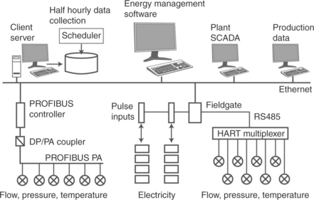
The instruments installed in the utility system monitor flow, pressure, temperature and electricity consumption. Where an energy value is derived from these quantities, the computing is done in separate module. The instruments and/or modules are connected to data loggers or remote terminal units (RTUs). These publish the energy and utility consumption data at regular intervals to a client/server application which stores them in a database. Normally this is done every half-hour, but any frequency is possible. Once the data have been collected, they can be used in a variety of ways.
• Import into Microsoft Excel spread sheets for manual energy analysis and report writing.
• Transfer to existing SCADA/HMI systems.
• Transfer to a packaged energy monitoring and targeting (M&T) tool.
An M&T tool provides a wide range of facilities for energy analysis, financial analysis, exception handling, budgeting and reporting on energy data. In addition to monitoring monthly energy consumption it provides the means to correlate this information to a driving influence providing a measure of the efficiency of a process.
It is estimated that on average, savings of 5–15% in energy cost are possible when simple measures such as those described are implemented.
3.6 Future trends
Although the sensing elements and associated electronics of a measuring device are always subject to continuous improvement, no radical changes are to be expected in the next few years. The same is true for digital communication: the fieldbus has established itself as a reliable alternative to the 4–20 mA current loop but it will be the market rather than new developments that determines the success or failure of a particular protocol. Plant Asset Management, on the other hand, is attracting a great deal of attention at the moment: since efficient operation also depends to some extent on the ability to plan and manage maintenance activities. Developments can be seen at several levels.
At the sensor level, NAMUR recommendation NE107 (NAMUR, 2006) proposes a simplified device-diagnosis scheme that sorts error messages into four classes: ‘maintenance required’, ‘failure’, ‘functional check’ and ‘out of specification’. This allows the user to assess the severity of the alarm before deciding whether the detailed information held by the device is needed. The recommendation has been incorporated into both PROFIBUS and FOUNDATION fieldbus specifications and the first devices with this form of diagnosis are already on the market.
As discussed briefly in Section 3.4 there are two open specifications that support device configuration and monitoring, EDDL and FDT. FDT was conceived with asset management in mind and has much broader support, which extends beyond measuring devices and valves. EDDs are part and parcel of every HART, PROFIBUS and FOUNDATION fieldbus instrument. Although FDT will bring out an enhanced specification in the near future, they are also co-operating with the EDDL group to specify a joint FDI (Field Device Integration) standard. This should open the way to easier integration of devices in plant management tools and better support of the solutions already offered, for example, condition monitoring.
A step further is the use of a plant asset-management tool to connect to the life-cycle data of a device: certificates, calibrations, order codes, spare parts or, in the case of discontinued lines, pointers to on replacement devices. This is information which, of course, can be manually entered into any database; however, it requires a great deal of effort to do this and is basically duplicating data that is held by manufacturer. Opening an internet portal with life-cycle data by simply clicking on a device tag or serial number is a possibility which already exists for some devices. A further click allows the replacement device or spare part to be ordered. This service is likely to be offered by most instrument manufacturers in the next few years.
At the time of writing, a concept for remote service management is being tested within in the so-called Future Factory Initiative (SAP, 2010), whereby measuring instruments are enabled as smart devices within an ERP tool. These can then create error tickets, notifications or alerts as well as transfer processing data to the service management application for installed-base configuration, management and maintenance. On detecting a problem, a device sends a notification to the service management application which forwards it to the service department of the user. Here the decision is taken whether the problem can be solved locally, or whether the device manufacturer should be involved. In the latter case, the message is again automatically forwarded to the manufacturer’s service centre, which then accesses the device remotely and proposes appropriate actions, if the fault cannot be remedied by reconfiguration. The result is an accelerated maintenance process which ensures that the best qualified person solves the problem.
3.7 Conclusion
The food industry represents a significant market for instrument manufacturers, who have not been slow to follow the demands made by increasing automation. Nowadays, reliable, hygienic instrumentation, which more often than not can be cleaned in place, is available for most process variables. Developments in the past few years have also led to more in-line analysis instruments, allowing automation of the corresponding processes. Finally, the user has a number of possibilities to integrate intelligent instruments into automation systems, allowing their full potential to be used.
3.8 References
Avesta Sheffield Corrosion Handbook. Stainless steels for the Food Processing Industries. ISBN 91–630-2122-6. Also available on-line as Outokumpu Steel Professional Tool. http://www.outokumpu.com/applications/documents/start.asp, 1994. [Accessed 24 September 2010].
Bentley, Springer. Handbook of Temperature Measurement Vol. 1: Temperature and Humidity Measurement, 1998. [ISBN-10: 9814021091; ISBN-13: 978-9814021098.].
Berrie, Kress-Rogers, Brimelow, Chapters 13 and 14, Woodhead Publishing. Instrumentation and Sensors for the Food Industry, 2001. [ISBN 1 85573 560 1.].
Council of Europe. Guidelines on Metals and Alloys Used as Food Contact Materials. http://www.bfr.bund.de/cm/216/guidelines_on_metals_and_alloys_used_as_food_contact_materials.pdf, 2002. [Accessed 24 September 2010].
FDA. Food Contact Substances (FCS), Food and Drug Administration, USA. Available from: http://www.fda.gov/food/foodingredientspackaging/foodcontactsub-stancesfcs/default.htm, 2010. [[Accessed 24 September 2010]].
FOUNDATION Fieldbus. Fieldbus Foundation. www.fieldbus.org, 2010. [Accessed 24 September 2010].
HCF. HART Communication Foundation. Available from: www.hartcomm.org, 2010. [[Accessed 24 September 2010]].
IEC (1995); IEC 60584-1 (1995) Ed. 2.0; Thermocouples – Part 1: Reference tables; International Electrotechnical Committee. (2001); IEC 60529 (2001-02) Ed. 2.1 Degrees of protection provided by enclosures (IP Code); International Electrotechnical Committee. (2008), IEC 60 751 (2008) Ed. 2.0, Industrial platinum resistance thermometers and platinum temperature sensors, International Electrotechnical Committee.
LiptakLipták, B.G., Eren, H., eds. Instrument Engineers Handbook: Vol 3, Process Software and Digital Networks, 2012. [CRC Press, ISBN-13: 978-1-4398-1776-6 (Hardback)].
MODBUS. Modbus Organization. Available from: http://www.modbus.org, 2010. [[Accessed 24 September 2010]].
NAMUR. Namur NE 107, Self-Monitoring and Diagnosis of Field Devices, NAMUR (International user association of automation technology in process industries). Available from: http://www.namur.de, 2006. [[Accessed 24 September 2010]].
NEMA. NEMA Standard 250, Enclosures for Electrical Equipment (1000 V Maximum). USA: National Electrical Manufacturers Association; 2008.
ODVA. ODVA. www.odva.org, 2010. [Accessed 24 September 2010].].
PROFIBUS. Profibus International. Available from: http://www.profibus.com, 2010. [[Accessed 24 September 2010]].
SAP. SAP Future Factory Initiative. http://www.sap.com/about/company/research/livinglabs/futurefactory/index.epx, 2010. [Accessed 24 September 2010].
Stahl. Basics of Explosion Protection, R.STAHL Schaltgeräte GmbH, 74638 Waldenburg, Germany. http://www.r-stahl.com/fileadmin/Dateien/explosionsschutz/pdf/grundlagen_en.pdf, 2007. [Accessed 24 September 2010]].