Robotics and automation in the poultry industry: current technology and future trends
Abstract:
This chapter discusses the current and future state of robotics and automation to enable a more efficient poultry processing facility. The chapter begins with a discussion of the unique challenges to automating poultry processing as compared to automobile or electronics manufacturing. The chapter then discusses the current production process with a focus on available solutions as well as prototype systems developed in academic labs. Finally, the chapter ends with a look into the future to see how robotics and automation can help maximize yield and improve food safety while minimizing labor costs and the use of natural resources such as water and energy.
14.1 Introduction
The modern poultry processing facility is an impressive combination of high technology solutions that have been arranged with the sole purpose of economically delivering a safe and affordable product to the customer. In the United States alone, the chicken industry, which is the largest component of the poultry industry, processes over 8.8 billion birds a year. As this number has climbed over the years, the industry has increasingly turned to robotics and automation to allow it to process birds in a faster and more efficient manner.
14.1.1 Unique characteristics of poultry processing and associated challenges for automation
In the modern chicken processing plant, the slaughter and evisceration line is typically running between 140 and 180 birds/min (3 birds/s). At these speeds, it is critical to have some automation because people do not perform these tasks well at these speeds. Typically, without causing injury to the worker, the upper end in speed for people tends to be in the range of 2–3 s per task. While these tasks were originally designed for the workers, the increase in production rates has made it difficult for the workers to keep up.
Compare this to other industries, such as the automotive and electronic industries where robotic systems have been very successful. In those industries, the speed of the tasks is much slower – anywhere from 10 to 30 s per task. Also, they are typically doing tasks that the typical worker does not do very well – be it lifting heavy objects (hoods of cars, engine blocks, etc.) or very accurately positioning components. In addition, the cost of an error is relatively large. If a tray of computer wafers is dropped or incorrectly positioned, then the entire tray might be lost at a cost of several millions of dollars. In addition, the robot is typically handling product that is very dry, rigid, and its physical attributes are very well defined.
In the poultry industry, the product is very different from that of the automotive and electronic industries. Birds vary rather dramatically in size, and the product is not rigid (especially when dealing with cut-up product like boneless breast fillets, and even bone-in-product is not as rigid as manufactured components due to compliance in the meat). This makes the use of traditional clamping style end-effectors difficult. In addition, the use of hard stops to precisely position product for handling does not work well, due to variations in product size and the compliance of the material. Further, the product can be slippery (boneless product or whole bird). This makes the development of end-effectors (hands) for robots very difficult.
Washdown is also a major driver in the design of any electro-mechanical system for the poultry industry. Unlike other industries, all equipment in a poultry processing plant must undergo a high-pressure washdown with the application of chemicals to the surface. Washdown typically will consist of using high-pressure water (at approximately 1000 psi (6895 kPa) at 120 °F (49 °C)) and the use of chemical cleaners/foams that have high acid and high base pH levels. The reason for the high-pressure washdown is one of the largest drivers for the entire industry: food safety. The extent that this affects all equipment cannot be overstated. The USDA and the National Sanitation Foundation (2002, USDA, 2001) have both issued very detailed guidelines on machine design for food processing. These requirements include the materials used, the types of fasteners that can be used, and how mechanical elements are to be joined. All of these factors have a tremendous impact on food safety, complicate the design of any electro-mechanical system and establish a set of ambitious requirements (AMI, 2003).
Differences in poultry processing around the world
Poultry processing is generally the same around the world, but there are some differences. Some of these are related to regulatory issues in the various countries, while others are due to local specialty products or to the types of birds raised in that area. For the most part, the initial processing of the bird (live hang, kill, and evisceration) are the same around the world. Most of the differences arise in the choice of chiller (water or air) and the further processing area (deboning and creation of the final product).
One significant difference between European and American production is the chiller. In the United States and most of South America, the water chiller is the method of choice to reduce the slaughtered bird’s body temperature down to 40 °F (4.5 °C), immediately after slaughter. The chiller provides an excellent thermal transfer coefficient such that the process can be done relatively quickly and with a small footprint. In Europe, an air chiller system is used to cool the birds. This method reduces the chance of cross-contamination between birds from immersion in a water bath. However, care must be taken to prevent birds from dripping on other birds throughout the air chiller. This reduction in cross-contamination is achieved at the expense of chilling time and floor space.
In further processing, the method of deboning the bird can vary based upon the preferences of the customer. Leg deboning in America is very different from leg deboning in Japan, for example. This unique market requirement dictates the design of the equipment and, in some cases, whether or not the cut can be automated.
14.2 Robotics and automation in live hanging and first processing of poultry
In the modern processing plant, the initial tasks of getting the live birds onto the processing line, killing the birds and eviscerating the birds (first processing) are key tasks. These tasks are fairly standard in the industry. While the live hang process still remains a huge challenge, first processing is very automated. This section will specifically address one method to automate the live hang process and by doing so, it will illuminate the complexities of the task.
14.2.1 Live hang
Birds are brought to the processing plant live and the goal of the first step in the modern processing plant is to hang birds onto the shackle line by their feet. The typical plant is running the live hang shackle line at 180 birds/min in the United States and over 240 birds/min in Europe. The task is laborious and very unpleasant for the workers as well as a potential safety hazard due to the dust, feathers and feces that are in the air. It is also dangerous because the birds want to peck and scratch at anything that grabs them. In an attempt to keep the birds calm, the live hang process typically occurs in an enclosed room that uses only red lights for the workers to see. Birds do not see well in red light so they tend to be more relaxed. In a processing plant, this is often one of the higher paid jobs because of the harsh working conditions.
Automating this task has been a priority for a number of companies and inventors for a good half a century. The economic justification for automating this task is clear: the salary for the worker, the extremely high turnover (in some plants, it is over 200% for this task), the safety of the worker and the safety of the birds. From an examination of the requirements for this task, it is clear that this is an extremely difficult task to automate.
The main difficulty in automating this task is obvious: the system must handle live birds. Live birds do not sit still on the conveyor and the designer must also take into account animal welfare. These are two very important points to consider in the design.
Potential solutions for this application are numerous and plentiful, but none to date have solved the problem. An exhaustive description of all the solutions attempted to solve this problem is outside the scope of this chapter, but a reference is provided. At Georgia Tech, we have been looking into this problem for many years. Dr. Lee, the leader of this effort, and his team (consisting of researchers from both Georgia Tech and the University of Georgia) have developed a concept based on the following distinct steps: singulation of the birds, orientation, leg capture, and inversion (Lee, 2001; Webster and Lee, 2002). This process would ideally be done in the dark or in a red-lit area to put the bird in as relaxed state as possible. Figure 14.1 is a picture of the prototype system being tested.
For the singulation step, a variety of approaches were considered. The team settled on a design that utilizes a set of counter-rotating drums with compliant fingers similar to those found in the defeathering process. These fingers are rubber and are pointed outward from a rotating cylindrical surface. The rotating fingers allow for only a single bird to pass at a single time without damaging the birds. The reaction of the bird to the fingers has also been the subject of much research (Lee et al., 1999, 2001). At this point, the key is to use a light that relaxes the bird but does not distract them.
As the bird exits the singulation system, it automatically aligns itself with the motion of the conveyor in one of two manners – either facing forward on the conveyor or facing backwards. Utilizing a vision system (either an IR camera if the room is completely dark or a regular CCD if the room is lit by a red light) to recognize the orientation of the bird, the system rotates the bird while in the grasp of the compliant grippers so that they are all facing forward (Lee et al., 2000; Li and Lee, 2005). (The IR camera is the special requirement for the system to work. IR cameras do not need any additional lighting or special consideration other than avoiding hot spots in the thermal image.)
The key variables to prepare the bird for the leg-capture phase are the difference between the speed of the body of the bird in the grasper relative to the speed of the conveyor (called the translational velocity), the posture of the bird, and the lighting conditions.
The importance of the translational velocity was a key discovery for the team. This also led the team to begin to analyze the kinematics of the legs of the bird in order to determine an optimal translational velocity for each individual bird. The translational velocity of the bird is an important component of the bird’s natural reaction to extend their legs downward in order to maintain contact with the downward sloping conveyor or retract their legs into their body. The desired response from the bird is to have it extend its legs so that they can be placed into the shackle. If the translational velocity is too high, the bird’s natural reaction will be to pull its legs up and into its body. If the velocity is too low, then the bird will stumble and possibly fall, thus making the loading into the shackle impossible.
To customize this for each bird, a vision system was developed to identify the physical parameters of the bird as well its posture as it approaches the compliant grasper. A neural network is then used to optimize the rotational velocity of the compliant grasper to achieve the desired translational velocity for each bird. The results of preliminary testing of this system validate the described approach, but much more testing is needed (Webster and Lee, 2002). The next step in the process is the actual leg-capture phase. As the bird exits the compliant grasper, its legs should be extended and it can be placed directly into a moving shackle that is placed horizontally on a conveyor. Once in the shackle, the conveyor drops away and the shackle is free to rotate into the vertical position and the bird is successfully hung on the shackle (Shumway, 2002).
It should be noted that this system is still very much in the research and development phase. Initial testing of the system has shown the validity of the core concepts, but a complete system has not yet been developed and tested.
14.2.2 First processing
First processing is typically defined as slaughter, evisceration and chilling. These are standard processes that are almost identical in every poultry plant. This has been driven by a number of different factors, and has resulted in a certain amount of standardization of the equipment to perform these tasks. This equipment is categorized as fixed automation – mechanized machinery to perform fixed and repetitive operations to produce a high volume of similar parts (AMI, 2010).
As discussed earlier, one of the biggest problems for processors is dealing with the size variation of the birds. However, instead of adjusting the equipment to each bird, the equipment is adjusted based on the estimated weight for an entire flock. Thus, as a flock moves through the process, the machines are manually adjusted for the weight range. While this might seem rudimentary, the system actually works quite well. The majority of tasks performed during this part of the process do not generally require the accuracy that robotics or sensor-based automation offers. While the equipment for this process is relatively expensive, the actual cost to process a bird is very low. Given the economics of the situation, it is hard to justify additional automation that is an incremental change to the system. The main producers of equipment for first processing include Marel/Stork, Meyn, and Baader.
14.3 Robotics and automation in second processing of poultry
Once the bird exits the chiller, it moves into second processing. This is defined as the deboning and portioning of the product, as well as packaging of the product into tray packs or bags/pouches. While first processing has almost been universally standardized, second processing is more defined by the product types and product mixes that a particular processor runs. Thus, each plant is unique.
Second processing is an area that has been the subject of considerable development of robotic and automated systems (Wyvill, 2005). These are typically tasks that the worker does not naturally do well because of processing speeds and accuracy requirements. While most of these tasks are justified on labor replacement, some of these tasks, such as breast deboning, can affect the yield of the product. In this specific case, the losses due to manual deboning can result in yield losses totaling several millions of dollars a year per plant. This is a strong incentive to automate this process.
14.3.1 Rehang after chiller
As discussed earlier, water chilling is not found in Europe since they use air chilling and the birds remain on the shackle during the entire process. In the United States and many other places, they still rely on immersion of the birds in a cold water bath to reduce their body temperature to under 40 °F (4.5°) at exit. The birds are placed in the chiller by removing them from the shackle and dropping them into the chiller where they are typically, but not exclusively, moved through the process via an auger. It should be noted that at this point in time, the bird has not been split into the front half and legs. It is typically referred to as a WOG (without giblets).
It is important to note that once it is removed from the shackle, the pose (position and orientation) of the bird is lost. Upon exit from chiller, the birds exit via a slide onto a table or circular conveyor system. At this point, the pose of the bird must be recovered so that it can be manually rehung onto the shackle line. This typically requires somewhere between 4 and 8 people per line to meet the production requirements. The task also requires that the workers hang the birds in a particular orientation on the shackle line to enable further processing.
At the Georgia Tech Research Institute, we have been active in developing an automated solution to this task. We have attempted to develop systems to automatically rehang the birds in two distinct manners: a fully robotic solution and a sensor-based fixed-automation solution.
The fully robotic solution was intended to be a stand-alone solution to this problem (Fig. 14.2). The system was designed to identify the position and orientation (the orientation of the legs as well as whether the bird was breast up or breast down) of the bird on a moving conveyor, with software to track the moving bird, an end-effector to grasp it, and a system to track the moving shackles. The system used a KUKA 15SL, a stainless steel washdown robot, with their conveyorTech software for tracking the bird and the shackle.

The end-effector was a particularly challenging part of the project. The natural variations of the bird, as well as the requirement to grasp birds that are either breast up or breast down, makes the design of a general purpose end-effector very difficult. Also, the legs must be kept a specified distance apart so that they can be placed into the shackle. The final design selected is sufficient, but clearly additional work is required prior to commercialization.
The system as developed did demonstrate several key concepts. First, the team was able to develop image processing software to accomplish the task. The system could identify the orientation of the legs on the conveyor and it could determine if the bird was breast up or breast down with a high level of accuracy. In addition, the project demonstrated how to handle a WOG without damaging the bird and a method to keep the legs in a position that allows for the hanging process.
However, the system was not economically feasible. The cost of the robot and vision system was too high and the cycle time of the robot too slow. From our initial tests, the cycle time was between 7 and 9 s.
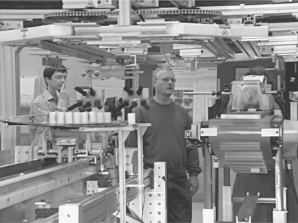
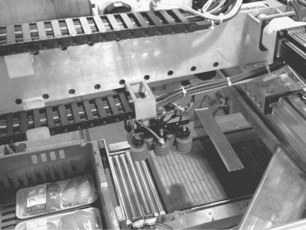
A second design effort was undertaken to develop a solution using only fixed automation to accomplish the same task. The birds are first singulated using a commercial system and fed individually into the mechanism. The system has been divided into a two step process. The first step is to put the randomly oriented bird into a specially designed box – breast up with the legs protruding from the box. The second step is to transfer the bird from the box onto the shackle. The first step is shown in Fig. 14.3 and consists of the following procedures:

1. WOG slides onto a platform. Due to the physical properties of the bird, the slide orients the birds either legs first or legs last.
2. An imaging system takes a picture of the bird to determine if the bird is legs first or legs last and whether it is breast up or breast down.
3. The bird is rotated, based on the orientation as determined in step 2, such that it is pushed legs first into the flipping mechanism on the right side of the picture.
The second step is shown in Fig. 14.4 and consists of the following processes:

1. The box from each loading station is integrated into a single line of boxes on a conveyor.
2. The box is transferred to the shackle loading system.
3. The bird is placed on the shackle line.
4. Empty boxes are removed from the shackle loading system back onto the conveyor.
This system is more attractive in terms of cost–effectiveness because it relies on relatively simple fixed-automation concepts. The only complicated part of the system is the image processing, but that problem was solved during the development of the fully automated solution discussed above. The problem with this system is the footprint of the system. The conveyors to move the boxes through the process and manage a buffer result in a footprint slightly larger than the current process. Given the congested nature of most plants, this could be a significant problem. Further work is needed to minimize the footprint while maintaining the adaptability of the system.
14.3.2 Cone loading
Following the rehang after the chiller, the birds are typically automatically sorted on the shackle line based on their weight to meet the particular needs of each processing plant. Once the birds are sorted, each bird is split in two by running it over a fixed blade. This creates a front half (wings and breast meat) and the bottom half (legs and thighs). Each half is processed in different manners.
The front half is typically placed onto a cone for either manual or automatic deboning (see Fig. 14.5). This task involves taking a stream of randomly located front halves and placing them on a cone. The placement of the bird on the cone is important. The goal of this is to place it such that a pin that is located on the cone (called the keel pin) penetrates a specific spot just above the rib cage. If this is done properly, the keel pin will hold the bird onto the cone and prevent it from rotating or moving during processing. For automated deboning processes, the placement of the bird is very important. Therefore, most companies have some mechanism that is used to pull it into the proper position on the cone. Most of these devices are cam operated and are simply fixed pieces of automation. There is not sensing or modification of the device based on the product. This can result in breaking or damaging the skeleton if the bird is not properly positioned on the cone.
At GTRI, a team designed an end-effector to work on the front half of the bird (Fig. 14.6). This task is complicated by several factors (Socha et al., 2004). First, the cavity of the bird must not be compromised for several reasons. First, the cavity must not reduce in diameter such that the bird could not be placed on the cone or prevent the keel pin from penetrating the desired location. Second, the grasping must not damage the wing in any manner. A vision algorithm was also developed to identify the orientation and position of the bird on the conveyor. For this work, GTRI researchers used stereo and time-of-flight (TOF) cameras to determine the 3D shape of the product on the conveyor. From the shape data, it was possible to identify the long axis of the bird as well as whether it is laying breast up or breast down. Because of the moments of inertia, the bird will not typically rest on its side when it is fresh. From this data, the algorithm also estimated the target point for the keel pin on the bird to facilitate the placement of the bird on the cone.

As can be seen in Fig. 14.6, the team was successful in developing an endeffector and imaging system to accomplish this task. The current system uses a commercial ABB robot to move the end-effector. A logical next step in this development would be to design and develop a commercial system to accomplish this task.
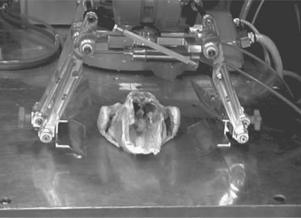
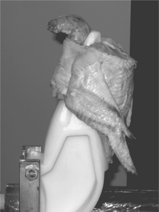
14.3.3 Breast deboning
Deboning operations are one of the largest users of on-line labor in today’s poultry plants. Efforts have been made over the years to automate this function, but to date they have achieved only limited success. The main difficulty in this task is its unstructured nature due to the natural variability in the sizes of birds and their deformable bodies (Fig. 14.7). To increase product safety and quality, the industry is looking to robotics to help solve these problems. This research has focused on developing a new method of automating the deboning of bird front halves. If this task can be automated, the technology would naturally be extended to other cuts and trimming operations in poultry and red meat.

The value in accomplishing this work would be not only to reduce labor costs but also to increase the yield of breast meat and reduce/eliminate bone chips. It is estimated that an increase in yield of a single percentage point could represent several millions of dollars of additional revenue for each and every plant. Current attempts at automation of the shoulder cut impose several percentage points of yield loss in return for lower labor costs. Currently, automated solutions are offered by the major poultry processing companies including Marel/Stork, Meyn, and Baader. These systems typically rely on a variety of mechanical adjustments to perform the shoulder cut. These adjustments are to account for the size variation of the birds based on lot sizes, as discussed earlier. However, the size variation of the bird at this step is particularly difficult to adjust for without resorting to robotics. The yield of these systems is approaching that of the average worker, but only if the machine is kept in constant adjustment based on the size of birds being run at that time. Actual practice has shown that this is difficult to do at best. In the manual process, while generally providing a higher yield of breast meat, the quality of the product varies dramatically based on the skill of the worker, and the labor costs are significantly higher. It is the goal of this work to develop a system that eliminates labor and consistently provides a yield similar to the best manual worker. The starting point for the work is that the bird is placed onto a cone as shown in Fig. 14.8.
The overall vision for this project requires the development of various technology components that will be unified into a single operational system. This includes a system to identify the initial cutting point, a system to specify the nominal cutting trajectory based on the size of that specific bird, a model to predict the location of the joint and shoulder tendons given the position/orientation of the wing tip, a mathematical model of the cutting process that allows the control system to interpret force/torque data and make intelligent motion commands to avoid cutting through the bone, and a robotic platform capable of executing these commands in real-time. The prototype cell is shown in Fig. 14.9.

For our work, we have divided the cutting process into three distinct cutting steps. These steps are found in every manual cut, but they can vary between individual plants. The first step is a cut from the clavicle to the beginning of the shoulder joint (Zhou et al., 2007a). This cut is important to separate the breast meat from the carcass in order to maximize yield. The second cut is to cut all of the tendons and ligaments that attach the wing to the shoulder. This cut can be a source of bone chips if not performed correctly. Finally, the last cut is from the shoulder joint down to and along the scapula bone. This cut is important for yield and it is also a possible source of bone fragments.
The team has identified the second cut, the cut through the shoulder joint, as the most technically challenging. We initially focused on the third cut and we were able to show the ability to cut along the scapula bone with a simple force-control algorithm. The success of the first cut is directly affected by the ability to accurately identify the initial cut position which is also very important to the second cut. However, the second cut is particularly challenging because of the requirement to cut meat and tendon, but not bone. In addition, the position of the wing plays a rather significant role in the success of the second cut, but it plays no significant role in the other cuts (Zhou et al., 2007b).
The importance of the position of the wings for the second cut cannot be underestimated. The width of the gap in the shoulder joint is determined by the position of the wings as well as the tension in the tendons and ligaments. Much like cutting a string with a pair of scissors, the string must be in tension in order to be cut. For the shoulder cut, the tendons and ligaments can lose tension while the shoulder is being cut and the gap in the shoulder joint can completely close if the wing is not properly held. For our work, we are investigating both active and passive wing manipulation systems. The advantage of the active system is that the tension and gap in the shoulder joint can be controlled during the cutting process to insure a quality cut (Claffee, 2006). However, this does result in a more costly system due to the extra manipulation systems. The passive system is much simpler to implement but it does not allow the system to maintain the ideal tension in the tendons and ligaments during the cut. The trade-offs between these two concepts are still being investigated.
To address the identification of the cutting point and predict the location of the bones and tendons in the shoulder joint, the GTRI conducted extensive modeling based on measurement of birds of all sizes (Daley and Grullon, 2010). This analysis allowed the team to develop an analytical model of the bird’s anatomy as a function of the three key points on the bird – one point for each wing where the wing meets the body of the bird and the tip of the keel, Fig. 14.10. These three points can be identified using a stereo vision system to get the 3D location of the points or a mechanical system can be used to identify and measure the points as well.

Based on the location of the three points, the model of the bird anatomy is used to identify the initial cut point for the robot and it generates a nominal cutting trajectory for that individual bird. This individualized cutting trajectory not only takes into account the size of each bird, but also its unique location on the cone.
Using the nominal cutting trajectory, the system moves the cutting blade such that it is located above the cutting point. As the cone line moves the bird underneath the waiting blade, the cutting robot inserts the blade into the carcass. At this point, the system begins to monitor the cutting force to ensure that the system cuts meat and tendon, but not bone. As might be expected, an increase in cutting force normal to the blade would indicate that the blade is contacting a more rigid material – meat, tendon, or bone. However, there are many factors that affect the force being applied to the blade during the cutting process. These include: properties of the material being cut, velocity of the blade, angle of the blade relative to the material (slice angle), and the sharpness of the blade (Zhou et al., 2006a, 2006b). Based on our modeling of cutting of biomaterials (Zhou and McMurray, 2007), GTRI has developed unique criteria for determining what the blade is cutting even though all of the above properties can vary significantly. This technique is able to identify when the blade has made contact with the bone such that the blade never penetrates more than 1 mm into the bone. An active research project at GTRI is focused on extending the bone detection algorithm such that it is insensitive to the blade sharpness. Blade sharpness has been a particularly difficult parameter to adjust for given the complex interactions of the above parameters and the difficulty in defining sharpness in practical terms. This work is focused on adapting the force cutting and bone detection algorithms to the ever changing blade sharpness, thus ensuring that the system can identify meat, tendons and bones from the very first cut with a sharp blade to the dullest blade used after several hours of cutting without resharpening (Zhou et al., 2006b).
Of course, the goal is to cut through the shoulder joint without encountering the humerus or coracoid bones, but due to the very small gap in the shoulder joint this is inevitable in a practical system. Once the bone has been detected by the above technique, the system engages a force-control algorithm that attempts to maintain a constant force on the unknown shape of the bone. This is required because the tendons and ligaments that span the shoulder joint are attached to these bones at some point. By maintaining contact with the bone, the blade is able to move around the bone to cut all of the tendons and ligaments without generating a bone chip.
The system that has been described is still an active research project at GTRI. There are still a number of technical challenges that lie ahead of the team before the system will be ready for commercialization. However, the core technology has been developed and the more basic research topics have been addressed. At the present time, the team is also investigating the more practical side of automating the cutting process. This includes defining the best way to hold/manipulate the wings of the bird during the cut, and the optimal angle of the bird to facilitate the cut. This second point is important in developing a robust cutting system. Given that this system might be cutting 300 000 shoulder joints a day, aligning the joint with the blade to minimize the side forces and provide a straight path to the major tendons only makes sense from a practical point of view.
14.3.4 Tray packing
After the product has been deboned, the parts move down a conveyor where a final manual trimming operation is performed (if necessary). In many plants, the product is now ready to be placed into a tray pack where it will be sold to the customer. The placement of product into trays is another very labor intensive process in the modern poultry plant. This task typically can require up to ten people per line.
In recent years, several commercial systems have been developed to address the tray packing problem. Robotic companies such as ABB and Fanuc have recently come out with solutions to automating this task. The systems typically consist of several key components: a vision system to identify the position and orientation of the product on the conveyor, an end-effector to grasp the product on the conveyor, and a robotic arm to move the end-effector.
One of the recent advances in the area of robotics that has been the basis of many of the commercial solutions has been the parallel robot. These robots have a much smaller work space and can handle much lighter payloads (typically under 1 kg) than the typical industrial arm, but they are significantly faster. The speed of these systems is what makes them well suited for this and many other food applications. These systems are gaining wide acceptance in the baking industry for these reasons. Typical applications include transferring cookies or croissants from one conveyor into the final package. Because of the high volume in which these products are produced, the system must be very fast and inexpensive, such that the price per part is very low. At this time, only the parallel robots can meet these criteria.
However, for the poultry industry, there is another criterion that the robotic system must meet: food safety. The machine must be able to go through a high-pressure washdown every day and the system must be tested to show that it will not allow pathogens to grow on it. As was discussed in the introductory section, the ability to clean the modern processing plant and the equipment in the plant has been an obstacle to the introduction of robotic technology in the past. Today, however, solutions to this are beginning to appear on the market and the research labs. The current products being offered on the market today are significantly more rugged than traditional industrial robotic arms, but they still cannot undergo the standard high-pressure washdown procedures. This means that the machines must be hand washed.
At GTRI, researchers have developed washdown technology to allow robotic devices to undergo a high-pressure washdown cycle that includes the caustic chemicals (Zhou et al., 2007c). The system is shown in Fig. 14.11. All of the materials used in the design of the robot are USDA/FDA approved, and all of the components have been tested for chemical compatibility with the cleaning agents used in a typical plant.

The prototype system that is shown in Fig. 14.12 was placed in a meat processing plant for field testing. The system was only run off-line, but actual product was used in the testing. The system was run at a maximum production rate of 70 parts/min and a vision system was used to identify the product and its position/orientation on the belt. If required, the throughput of the system can be improved through the addition of a second end-effector by extending the linear axis in the other direction. The results of the test showed that the design was sufficient to allow a robot to undergo a normal high-pressure washdown procedure without impacting the performance of the machine. In addition, surface swabs from the machine were also tested to determine the effectiveness of the design in insuring food safety. The testing revealed no signs of pathogens or any food safety issues.

A key result of this project were a lessons learned for developing a washdown robot. These include:
• Seal considerations – Redundant sealing is recommended for all critical sealing points where caustic cleaners have the potential of causing severe damage to the machine. FDA approved lip seals can go a long way to prevent ingress into critical areas.
• Bearing selection – FDA approved bearings that do not require lubrication are preferred due to the lack of maintenance and durability; however, care must be taken to select a robot configuration to limit loads and speeds (pressure– velocity ratings) to within the manufacturer’s ratings.
• Horizontal surfaces – Even if the base material is resistant to all food processing cleaners such as some stainless steel alloys, the lack of draining can still result in pools of liquid on the surface which are undesirable.
• Laser-cutting comments – Many of the machine elements were fabricated by using a laser-cutting system to cut stainless steel sheets. This method of fabrication must be handled with care because splatter from the laser-cutter supports can create contamination on surfaces of the parts, which, if not sanded or blasted with media, can result in severe rusting. Waterjet cutting removes the risks of contamination present in laser-cutting fabrication methods.
• Drain holes – Unless electronic equipment undergoes the costly procedure of hermetic sealing, drain holes are compulsory to prevent moisture from building up in equipment in washdown areas.
• Location of primary electronics equipment – Most machines can be operated by controllers located several meters from the actual manipulator. This can be used to the advantage of equipment providers if less severe areas are available for placing critical electronic equipment. Although pneumatic valves are one item that must be located close to the robot, low-cost commercial solutions exist to address this issue if they are properly guarded in a washdown capable enclosure.
• Underwater cables – Underwater-rated cables and connectors have integrated O-rings in the back shells to help to ensure signal integrity.
From a regulatory point of view, the following lessons learned resulted:
• Designing for cleanability from the beginning – Placing cleaning considerations as early in the design process as possible prevents excessive redesign later in the design process where changes to the design are more costly. Referring to the AMI equipment design guidelines will also help to ensure equipment will meet the requirements of inspection staff at the plant where the equipment is to be installed (AMI, 2003). Keep in mind that inspection of equipment can differ from plant to plant meaning more robust hygienic designs will have a larger potential market.
• FDA/USDA-approved materials do not guarantee acceptance – Although various materials and platings are sufficient for FDA/USDA approval, appearances and acceptance requirements which are plant specific may preclude the use of some materials such as plated aluminum surfaces.
• ANSI/RIA standards – All safety standards must be followed to ensure the safety of personnel.
14.4 Robotics and automation in bulk packing and shipping of poultry meat
Once the product has been shrink-wrapped or boxed in some form that protects the raw product from the environment, all handling tasks become very similar to those found in non-food facilities. Therefore, this is the area that has in recent years taken advantage of the commercial robotic systems. While there is still a temperature requirement for the product to inhibit the growth of pathogens in the product, it can, otherwise, be handled exactly like other industrial products.
The modern industrial arm has become a very cost-effective alternative to manual labor (Fig. 14.13). In addition, the mean-time-to-failure for the modern robotic arm is approaching 100 000 h. This translates into a lower initial cost of a robotic system while dramatically decreasing the operational cost of the system through less down time and repair costs.

For the modern poultry plant, one common final form for the product is the tray pack. This is a tray that has been individually shrink-wrapped and is meant to be sold individually to the consumer, typically at the grocery store. The task of loading the individual trays into a shipping carton has been a task that has been difficult for the industry to automate to date.
The reason that this task has not been automated can be traced back to the requirements for this task. First, the typical plant is running between 30 and 60 trays per minute. As discussed earlier, this is a difficult speed for traditional robotic arms. Because of the diverse packing patterns used by the plants for their diverse product set, it is generally not possible to create a packing pattern and then load multiple trays simultaneously, as is common practice in many industries.
Another difficulty in automating the tray packing operation is the vertical distance between the trays and the bottom of the boxes. While the vertical depth of many of the shipping boxes is less than 12 inches (30 cm), the boxes are usually formed with the flaps standing straight up. This means that the vertical distance between the box conveyor and the tray conveyor must be the height of the box plus the height of the flaps. This can easily result in a travel distance of over 24 inches (60 cm) for the robot to pick up the tray pack and place it in the bottom of the box without dropping it. This vertical stroke is greater than the vertical motion range of most parallel robots (the ABB Flexpicker, shown in Fig. 14.14, has a 12 inch (30 cm) vertical stroke limit).

To address this market need, GTRI worked with a commercial company, CAMotion, to develop a case packer to meet the unique requirements outlined above (Dickerson et al., 2005). The system developed consists of 3 degrees of freedom (XYZ motions) that can grasp and place a tray at the rate of 60 trays a minute. The specially designed end-effector was designed to account for the variations in the surface of the tray as well for frozen or non-frozen trays. A picture of the system is shown in Fig. 14.15.
The next step in the process is typically the pallet loading process. This task is generally fairly easy to cost justify for a poultry company. Pallet loading takes place after the product has been placed into a shipping box and the boxes are loading onto a pallet for bulk shipping. What makes this task easy to automate is that the boxes are fairly rigid and well-defined products at this point and, as such, easy to manipulate with an industrial robot. The speed of the task is not as demanding as those found in other parts of the plant and the packing patterns on the pallet are very well defined. In many of the newer plants around the world, this task is almost always automated.
The next task that can be automated is the wrapping of the pallets to keep the boxes on the pallet from shifting during transport. There are a variety of semi-automated solutions as well as fully automated systems on the market today. The semi-automated solution typically requires the user to either set or build the pallet on a rotating platform and then input the size of the pallet into the controller. After this is complete, the user manually starts the shrink wrap on the pallet and then turns on the system. The shrink wrap material is automatically dispensed as the pallet rotates on the table. The system automatically moves in the vertical direction to provide complete coverage of the pallet. Internal sensors are used to maintain the proper tension in the shrink wrap material during the entire process.
The automated solutions are more convenient to use. One new system on the market is actually a small automated mobile robot from Italdibipack Group and the product is called the Robot Leonardo2000. The user can move the robot to the pallet anywhere in the plant and simply turn on the automated shrink wrap process. The robot has a sensor on the front that maintains contact with the pallet while it drives around the pallet applying the shrink wrap material while maintaining the proper tension in the material. The operator still has to input the height of the pallet, but the rest of the process is automated.
Once the pallet has been created, the pallet can be handled just like any other product in the supply chain. If desired, automated guided vehicles (AGV) can be used to transport the pallets to and from the freezer or refrigerated areas. These systems are mobile flatbeds or forklifts that can follow predefined paths to move product from one location to another inside of a company. Companies such as JBT Corporation and Egemin Automation can provide full service products to meet the demands of the poultry processing companies. In addition, automated storage retrieval systems can be used to handle the warehousing needs. Two companies in this area are Consafe Logistics and Dematic, but there are many other companies in this space. These systems automatically transfer product from the AGV to a mechanized tote to be stored in a warehouse and retrieved from the warehouse: all without requiring any human involvement.
14.5 Future trends
As the poultry moves into the next decade, there is a sense that the industry is ready for a change in processing technology that has brought them so much, but now seems so fragile. As food safety requirements are increased by government agencies and the cost of feed and oil increase as well, this presents an opportunity to rethink the process and optimize the process for a new set of variables: animal welfare, sustainability, food safety, yield, and labor.
While it is impossible to look at our crystal ball and accurately predict what the process will be, it is possible to identify technologies that will play a major role in reshaping the processing landscape in the future as the industry tries to meet these new set of goals.
First, I see the plant of the future to be a data-driven process. Data and analytics will be used to better estimate the size of the birds at the grow-out house to optimize their delivery to the processing facility so that their weights match the current orders of the plant. Live hang will eventually be replaced by a more acceptable slaughter process that will require a new method of loading the birds onto the shackle. Given that the birds will be killed or stunned in bulk, the loading problem will manageable since they will not be moving.
Once the birds enter the plant, a 3D model will be constructed and the weight and yield of each bird will be automatically calculated. From this data, the exact settings of the entire process will be determined and communicated throughout the process. This will allow something that the automotive industry and other manufacturing industries have been searching for decades for: processing down to lot sizes of one. Each process will be optimized for that bird so that nothing is wasted and the most value of every bird is obtained by the processor. It will also minimize the use of precious natural resources such as water and energy in the process.
As the bird moves through the process, data will be collected during the process to verify food safety (temperature of the product, digital image of product as well as a time stamp). Product traceability from the grow-out house to the tray pack leaving the plant will be guaranteed as well. This means that the water chiller in the US will have to change. Will it go away and be replaced by the air chiller or will cryogenic freezing of the bird replace the water chiller? I do not know, but the drive to reduce water and food safety tracking will eventually cause it to go away.
Throughout the entire process, no hands will touch the product unless there is an exception in the process. I dare not predict the order in which the changes in the process will occur in the future as there are many possibilities that have yet to be explored to answer that question. However, of one thing I can be sure: the creativity of the people working in this industry will be released like it has never been before as academia and the industry begin to team up together with a clean sheet of paper and ask the question: ‘what would the process look like if…?.’
14.6 References
Requirements for the Design of Meat and Poultry Processing Equipment. NSF/ANSI/3-A 14159-1 – 2002.
AMI, Fact Sheet: Sanitary Equipment Design. American Meat Institute., 2003.
AMI, 2010. Available from: http://www.toolingu.com/definition-300100-12475-fixed-automation.html [Accessed].
Claffee, M.R., The effects of wing manipulation on automated cutting of biological materials. M.S., Georgia Institute of Technology., 2006.
Daley, W.D., Grullon, S., stewart, J.M., Patent Application Number 12/608,939, 2010.
Dickerson, S., Coleman, S., McMurray, G.V., Holcombe, W., Prince, J., The commercialization of a low-cost, high-speed pick-and-place casepacker. XVII European Symposium on the Quality of Poultry Meat. Golden Tulip Parkhotel Doorwerth, Doorwerth, The Netherlands, 2005.
Lee, K.-M. Design criteria for developing an automated live-bird transfer system. IEEE Transactions on Robotics and Automation. 2001; 17(4):483–490.
Lee, K.-M., Webster, B., Joni, J., Yin, X., Carey, R., Lacy, M., Gogate, R., On the development of a compliant grasping mechanism for on-line handling of live objects. Part II: Design and experimental investigation. ASME International Conference on Advanced Intelligent Mechatronics (AIM’99). IEE, Atlanta, GA, 1999.
Lee, K.-M., Joni, J., Yin, X., Imaging and motion prediction for an automated live-bird transfer process, ASME Dynamic Systems and Control Division-2000, 5–10 November. IEE, Orlando, FL, 2000:181–188.
Lee, K.-M., Joni, J., Yin, X., Compliant grasping force modeling for handling of live objects. May 21–26 2001 IEEE International Conference Robotics and Automation, Seoul, Korea, 2001.
Li, Q., Lee, K.-M., Effects of color characterization on computational efficiency of feature detection with live-objective handling applications. 2005 IEEE/ASME International Conference on Advanced Intelligent Mechatronics (AIM 2005), 24–28 July, Monterey, CA, 2005:225–230.
Shumway, C., Dynamic modeling and analysis of body inversions. M.S., Georgia Institute of Technology., 2002.
Socha, K.G., McMurray, G.V., Holcombe, W.D., Lipkin, H., Design of a compliant end effector for grasping non-rigid materials. International Conference on Intelligent Manipulation and Grasping, 2004 Genoa, Italy, 2004:253–258.
USDA, USDA Guidelines for the Sanitary Design and Fabrication of Dairy Processing Equipment, 2001.
Webster, A.B., Lee, K.M., Toward automation of the transfer of broilers to the processing line. WATT Poultry USA, 2002. [September, 28–42.].
Wyvill, J.C. Dynamic Process Control in Poultry Processing and the Technology Tools Helping to Make It Possible. Athens, GA: University of Georgia; 2005.
Zhou, D., Claffee, M.R., Lee, K.-M., McMurray, G.V., Cutting, ‘by pressing and slicing,’ applied to robotic cutting bio-materials. Part 1. Modeling of stress distribution. 2006 IEEE International Conference on Robotics and Automation (ICRA 2006), May 2006, Orlando, FL, 2901, 2006.
Zhou, D., Claffee, M.R., Lee, K.-M., McMurray, G.V., Cutting, ‘by pressing and slicing,’ applied to the robotic cut of bio-materials. Part 2. Force during slicing and pressing cuts. 2006 IEEE International Conference on Robotics and Automation (ICRA 2006), 15–19 May 2006, Orlando, FL, 2006:2256–2261.
Zhou, D., Holmes, J., Holcombe, W., McMurray, G., Automation of the bird shoulder joint deboning. 2007 IEEE/ASME International Conference on Advanced Intelligent Mechatronics, 4–7 September 2007a, Zurich, Switzerland, 2007.
Zhou, D., Holmes, J., Holcombe, W., Lee, K.-M., McMurray, G., Automation of bird front half deboning procedure: design and analysis. FToMM 2007 World Congress in Mechanism and Machine Science, 17–21 June 2007b, Besancon, France, 2007.
Zhou, D., Holmes, J., Holcombe, W., Thomas, S., McMurray, G., Design of a fresh meat packing robot for working in washdown environment. 2007 IEEE/ASME International Conference on Advanced Intelligent Mechatronics, 4–7 September 2007c, Zurich, Switzerland, 2007.
Zhou, D., McMurray, G., Formulation of the relationship between tension loading rate and internal stress for uni-axial bio-materials. IASTED 2007 Modeling and Simulation Conference, 30 May–1 June 2007, Montreal, Canada, 2007.