
Gripper technologies for food industry robots
Abstract:
This chapter gives an overview of the challenges of gripping food objects, the main answers to these challenges and some indications of possibilities offered by new gripping technologies. Conventional pinch gripping technologies are discussed and newly developed methods based on penetrating, suction and freeze methods are described. The basic governing equations for pinching and suction gripping are presented. The hygienic quality of the different methods is discussed. Finally a qualitative evaluation of the suitability of the different methods in food handling is presented.
7.1 Introduction
Since the invention of the first industrial robot by George DeVol in 1959, the gripper has been an integral part. The whole idea of robots is based on the concept of some non-human device that can perform tasks normally done by humans. It can be in manufacturing or any other human activity where a machine is used to replace the human action. In many of these cases the task involves gripping some object and doing something with it. It might be a simple transportation from one place to another, or a more complex task involving the use of some sort of tool and processing.
The modern ideas and implementations of robots have expanded from the original industrial applications for the first robots based on DeVol’s patent. The original industrial robots were truly material handling devices and nothing more. For that reason the gripper was an essential part of the robot.
But unlike the robot arm and control system, the grippers have not been the subject of the main research activities in robotics. There has been research on mechanical hands with human-like fingers, but still the bulk of research seems to have been concentrated on robot control theory, arm structures, kinematics and dynamics, and on robot sensory systems.
Grippers can be profoundly simple. A device with two mechanically actuated fingers that can pinch an object is all that is needed in many simple handling cases. Since there are so many applications where this gripper is sufficient, the research effort has been spent on the more interesting and mathematically challenging aspects of robotics. The well-functioning, simple two-finger gripper is too simple to challenge the minds of the researchers.
But times have changed. All the simple cases are so well studied. Instead the robotic world is facing challenges in handling soft, limp, ‘unstructured’ objects. These are the objects that are found in great numbers in food industry. Handling fruits and vegetables, and meat from sea or land animals, poses problems that are not immediately solvable with the simple gripping technology of the first generation robotics.
Slowly, in the period from around the new millennium, insight has been developed into more sophisticated gripping methods and technologies for all of these objects of soft, limp or unstructured character. As these new gripping methods and technologies become well understood and developed to industrial standards, new opportunities for automation in a vast number of industrial applications will appear.
In this chapter the term ‘hard gripping’ will refer to any gripping task where the object has a well-defined shape and is strong enough to withstand the force of a pinching or similar gripping method. Typically, gripping a metal screw or plate can be considered to be a hard gripping case
‘Soft gripping’ will be used to characterize any gripping task where the object is of soft materials that can be easily influenced by the force of the gripper, and by any acceleration, and in addition the object may be of irregular shape that will vary from object to object of similar kind. Gripping a piece of beef is a good example of soft gripping.
Food objects are often soft-grip objects, even if many food objects could be handled with hard grip technology. This chapter will cover both types of gripping technologies, but it will put most emphasis on soft gripping.
7.2 Gripper challenges in food process automation
In general food materials present challenges that are not normally seen with non-edible products. Some of these challenges are also seen in products other than food, notably softness and limp behaviour of textiles and certain foam plastics and in rubber products. But many of the challenges in food handling are unique when the combination of challenges is considered (Chua et al., 2003).
Certain well-developed gripper solutions can be transferred from the non-food sector into food handling. But all special requirements in the food sector have to be considered. This consideration has lead to some interesting and unique gripper solutions for automatic handling of food materials.
7.2.1 Soft materials
Much food material is soft. This comes from the nature of food. Food material is either vegetable or meat. Meat is always soft while vegetable food can be soft or hard. The hard food material causes fewer problems from the gripping side. But all soft vegetable food materials are potential problems in handling.
There are two major problems with soft materials:
1. The material changes shape so that a fixed-width pinching device simply loses its grip on the object.
2. The gripping force applied can damage the surface or interior of the object so that quality is reduced. This generally leads to lower selling price or shorter life of the object.
For this reason soft materials require a gripping method that eliminates these problems.
For meat from land animals the problems of type two are insignificant. Meat is generally robust enough to tolerate normal forces from pinch gripping. The softness does mainly lead to the problem of the first type for meat. This might not matter if it were not for the aggregation of problems due to uneven surfaces and non-uniform shapes.
Fruits are in a different category. Soft fruits require very gentle handling. Even semi-hard fruits like apples and tomatoes are very sensitive to denting and local pressure. In general the pinching grip is not suitable for any of these.
Other vegetables are easier to handle – nuts and roots of different kinds are generally more tolerant to gripping forces.
7.2.2 Uneven surfaces
All naturally grown objects have uneven surfaces. For some specimens the unevenness is only slight, while others have very rough surfaces. The surface quality can influence the range of gripping options.
Hard objects with rough surfaces are normally the easiest to grip. Such objects are tolerant to high gripping forces. Soft objects with rough surfaces, on the other hand, present challenges. Kiwi fruits can serve as examples here. These fruits are very sensitive to denting and local pressure, and the skin is rough, making it difficult to use vacuum gripping techniques.
Meat from both fish and land animals also presents problems due to uneven surfaces. Vacuum techniques are difficult to apply because of the unpredictable surface structure in many cases.
7.2.3 Non-uniform shapes
All organic objects have imperfect geometrical shapes. It is only fabricated objects that can present perfect outer geometry. Some food materials come in this category; most notable are chocolate products that are cast in dies that produce perfectly regular shapes. But all naturally grown objects show some irregularities.
Many processed object are similarly non-uniform. Different cuts of meat from animals will always have some irregularity even if the cutting process is set up to produce very regular shapes. Breads, cakes and pastries can be produced to quite regular shapes; however the preference of many customers is that these products should be irregular to give a ‘home-made’ appearance.
Non-uniform shape is the biggest challenge for gripper design and methods. But in recent years the development of technology that supports the gripping task has provided many new options for reliable gripping solutions
7.2.4 Hygienic requirements
Since food is to be eaten there is an absolute, no compromise, requirement for hygienic treatment of food in harvesting and processing. Contamination of any kind must be avoided. Basically there are three major classes of contamination to be concerned with:
1. Toxic contamination: in the harvesting and processing no toxic substance should come in contact with the food. Traces of toxic substances can adhere to the product and thus be transmitted to the consumer. This implies that all gripping devices and methods should be of non-toxic materials. This is important to consider, since some engineering materials have toxic effects.
2. Bacteriological and fungal contamination: bacteria of all kinds have the possibility of growing where there is organic material, and favourable humidity and temperature. Fungi can also find favourable living conditions in humid areas. These conditions can easily be present in any food processing facility. All gripping methods that rely on physical contact with the object do also generate the risk of leaving small amounts of the handled material on the gripping device. Temperature and humidity will often be favourable for bacteria and fungi on the premises if there are humans in the processing area, due to the requirement for acceptable working conditions for humans. Therefore all gripping devices should be designed so that the accumulation of organic material is reduced to the absolute minimum, and that efficient cleaning methods exist for the equipment.
3. Discolouring: some handling and gripping methods may lead to discolouring, by leaving small traces of material that might not be harmful but will be visible. Local pressure from gripping actions may lead to discolouring because of small changes in material structure. Even if such discolouring has no effect on the nutrient value of the food it will often be considered as a quality defect by the consumer.
The first and second classes of hygienic requirements are absolute. The third class is a ‘nice-to-have’ requirement but it does not represent a true health hazard.
7.3 Gripping physics
All grippers should perform the basic function of transferring the necessary force from the robot arm to the object in order to move the object. Any movement involves acceleration, through gravity and the local movement path. The acceleration in the local path is a function of any change in magnitude and direction of the speed vector.
Acceleration due to gravity is always directed perpendicular to the local horizontal plane. For vertical movements this acceleration adds to the local path acceleration for a movement upwards. This will normally give the largest force exerted during a handling operation.
Some gripper methods require at least partial enclosing of the object. This is the case with pinching and enclosing grippers. Others act on a single surface of the object. This is the case with pinning, underpressure and surface effect grippers.
For food products the following options for force transfer through the gripper exists:
• Pinching: the gripper has two or more fingers that apply force to the handled object. Straight fingers rely on friction force between the object and fingers to transfer the necessary force to keep the object in a safe grip during handling. Grooved or circular shaped fingers can also transfer force through local perpendicular force vectors. Since a large force is always exerted on the object this is a typical hard grip. Release is obtained by moving the fingers away from the object.
• Enclosing: the gripper relies on fingers with large surfaces that enclose the object partially or completely. The enclosure must be complete in the sense that all possible escape directions from the gripper are closed by suitable surfaces. The required force transmission to the object is obtained from the vector sum of all normal force vectors of the surfaces in contact with the object. In this case there is no force larger than the force of gravity and the acceleration forces from the gripper walls that act on the object so this is a soft grip.
• Release is obtained by moving the enclosing surfaces sufficiently away to create an opening large enough for the object to escape.
• Pinning, penetration: the gripper has several sharply pointed pins that are pressed into the object in a manner that creates a locking pattern. Usually this means a set of pins pointing inwards toward the central area of the object.
The objects must be of types that are not harmed by pin penetration. In food processing this can be the case for certain meat products. Release is obtained by pulling the pins back into the gripper body.
• Underpressure, suction: these grippers are often called vacuum grippers. They do not however rely on total vacuum, but rather on a certain amount of underpressure in the gripping area. Underpressure means that the local pressure in the gripper area is lower than the ambient pressure. This creates a force due to the pressure difference, which forces the object against the gripping area. Release is obtained by removing the underpressure; sometimes a slight overpressure is required for consistent release.
• Surface effects, surface phase transitions: gripping can be obtained by cooling down a contact area to a temperature well below the freezing point of water. When this area is brought in contact with a wet object, a thin ice film is created immediately on the object surface in contact with the cold gripper surface. This ice creates a sufficient holding force for many objects. Meat does normally have enough water content on the surface to enable this gripping action. Release is obtained by heating the contact area, or by slicing away the object by means of a thin knife (Lien and Gjerstad, 2008; Gjerstad et al., 2006).
7.4 Pinching and enclosing grippers
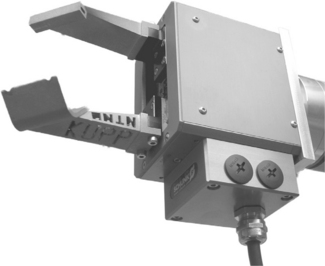
The pinching gripper is the original gripper concept for robots. It is a very simple and robust gripping method, and it is very efficient for a large number of different gripping tasks. There are several variants of this gripping principle, from two stiff-finger pneumatically operated grippers to multiple-jointed finger variants (Wolf et al., 2005). For practical robot applications the two and three stiff-finger variants dominate. Figure 7.1 shows examples of these gripper types.

7.4.1 Two-finger solutions
Typical two-finger grippers have the appearance of a prismatic body with two fingers extending from one side. The fingers are either moving in parallel or rotating around a shaft at their base. Normally they are actuated by pneumatic power, but electric and hydraulic actuation does also exist. The fingers are either flat-faced or have circular or v-grooves.
Two-finger flat-faced finger grippers rely on friction to generate the necessary force for holding the object. The force required depends on the direction of the acceleration in the movement. Figure 7.2 shows the four different principal force states that can occur depending on the direction of movement. This is called a force-fit grip.

Fig. 7.2 The forces acting on an object in different acceleration cases: m is mass of the handled object, a is the acceleration of the object due to the robot movement and g is the acceleration due to gravitation.
In all cases the gripper fingers transmit a force Ff opposing sliding along the gripper surface:
Ff: the friction force opposing sliding, F: the normal force on the finger face, μ: the friction coefficient between the object and the fingers, n: the number of fingers. To avoid sliding, Ff for a two-finger gripper must satisfy the following conditions depending on the direction of movement:
Horizontal parallel to finger face:
Horizontal normal to finger face:
For the horizontal movement normal to the finger faces, the acceleration force from the movement will actually increase the total force on one face and reduce it with the same amount on the other face. But the sum of forces will remain constant rendering the equation valid for all accelerations.
The grooves will give gripping force through form enclosing action. This is called form-fit gripping. The gripping force is the resultant of the individual normal force vectors from the contact surfaces. The calculation for this type of grip is presented in the section for multi-finger gripping.
The grip finger force F for pneumatically operated grippers is normally dependent on the supply pressure to the gripper. In most cases the force will exceed the level for minimum Ff by a very large margin, often several orders of magnitude. These grippers will always close to a position where the reaction force from the pinched object equals the finger force F. In the case of handling hard metallic, wooden or plastic components this is of no consequence. For fragile food materials the case is different. The gripping force must often be adjusted to the absolute safe minimum to avoid damage due to local pressure on the objects.
7.4.2 Two-finger servo gripper
One solution to the problem of excessive gripping force is the use of an electric servo gripper. This type of gripper is controlled to give a specified gripper gap, or to grip with a specified grip finger force F.
Externally these grippers differ little from pneumatically operated grippers except that the actuator housing is somewhat bigger, see Fig. 7.3. They are also more expensive, but the extra cost can easily be justified by the higher versatility of this gripper type.
The servo gripper requires a digital command specifying the wanted finger gap and grip force if force control is implemented. This command is normally transmitted via serial link from the control system.
7.4.3 Multi-finger grippers
Multi-finger grippers are of three main classes:
1. Simple stiff-finger grippers with three or four fingers.
Equations [7.1], [7.2] and [7.3] are valid for grippers with any number of flat-face stiff fingers when the gripper is used with its centreline vertically oriented. These grippers operate partially as form-fit grippers when operated in other positionings. Form-fit grippers rely on partially enclosing the object with the fingers, also sometimes using grooved or contoured fingers.
Form-fit gripping does not require high force from the fingers to create the friction force to hold the object. This gripping method relies on the fingers’ ability to withstand the normal force at the contact points at any position and acceleration. This will always lead to lower maximum finger grip force than force-fit gripping.
The anthropomorphic (human-like) grippers should ideally mimic human handling best. Many of the grippers in this class have less than the total degrees of freedom that we find in the human hand, only a few laboratory examples come close to mechanically mimicking the human hand. Thus the dexterity of the human hand cannot be fully emulated. Furthermore, the sensitivity of the human hand, through tactile and force feedback through the human nerve system, has proven very difficult to mimic. In addition the mere complexity of the human-like finger grippers has lead to extremely high cost, making them economically unsuited for industrial use at the present stage of development. This might change in the future (Mouri et al., 2002; Thayer and Priya, 2011).
7.4.4 Enclosing grippers
Enclosing grippers are designed so that they constitute a nearly closed box that embraces the whole object when closed. Thus they are able to handle all variations of a product as long as it fits inside this box. The shape of this box is normally not a rectangular prism; a ‘boat shape’ is sometimes a more appropriate description. The gripper does not exert a pinching force unless the object completely fills the box volume. In most cases the force to move the object is exerted from the box wall supporting the object in the direction opposite to the combined force vectors of gravitation and acceleration in the local movement.
The enclosing gripper will not provide exact positioning and orientation unless the object fills the box completely. In most applications it will therefore be suitable only if the delivery position and orientation is not critical, or if additional alignment devices are used at the delivery station. In many cases of packaging this is no problem since either there is room that allows variation of delivery into the package, or some simple guide walls are used to lead the object into its final position.
Figure 7.4 shows an example of an enclosing gripper

7.4.5 Hygienic performance of pinching and enclosing grippers
All the grippers of the pinching and enclosing class have some sort of moving mechanical elements outside the gripper base housing. Moving fingers require bearings, guides and shafts passing through walls. These elements are always a concern with respect to hygienic requirements. They should be designed so that there are no narrow slits, grooves or openings to the interior of the gripper where small particles of the food material and moisture can collect. It is a challenge to design pinching grippers to avoid such particle-collecting areas. In particular parallel finger grippers are difficult to design according to hygienic requirements of this kind because of the guideways necessary for the finger movement.
Another aspect is the geometry of the gripper fingers. They should have a smooth surface and no concave areas that will collect particles of any kind. Some gripper fingers have a serrated surface on the actual gripping face. For many food applications this is unsuitable, since the serration grooves are particle collectors that are difficult to keep clean.
The mechanism of a gripper needs lubrication. Complete sealing against long-term leakage is difficult to obtain. A better solution is then to use bearing materials that are lubricated by water, or polymer-against-metal bearings that can operate without lubricants.
Finally, the materials that will be exposed to the food handled must be of hygienically acceptable quality. In practice that implies stainless steel and polymers as materials for fingers and outer housing walls of a gripper.
7.5 Penetrating (needle) grippers
Penetrating grippers can represent a viable alternative for handling food goods in many cases. They are suitable for foodstuffs that are soft and can be penetrated without harmful effect on their quality. Primarily they are usable for meat, but it is possible that they could be used for soft cakes as well. These grippers rely on the use of several needles that penetrate the surface of the object to create a mechanical grip. This punctures the surface, and the basic requirement for the usage of such grippers is that this surface penetration is allowed. Both hygienic and quality considerations are important here.
Some meat processing relies on needles to inject processing fluids like salt, spices or taste enhancers. In these cases, as puncturing of the surface is necessary, additional puncturing from a gripper is then of no consequence. In other cases the puncturing leaves marks that are hardly noticeable. This gripper type is an interesting alternative because it can give a very strong and precise grip.
The advantages of a penetrating gripper are:
• Single side grip that makes it easy to grip and deliver in confined space.
• Very strong grip due to the physical penetration of the gripper into the tissue of the object.
• Precise positioning due to the physical interlock between the needles and the object.
• High accelerations and transfers speeds can be obtained due to the strong grip obtained.
• Puncturing of the surface can cause bacterial and other contamination. Mechanisms to ensure cleaning of the needles and the other surfaces that come in contact with the object are mandatory.
• Puncturing leaves holes in the object. These holes represent visual quality degradation. In some cases such quality degradation is not accepted.
• High acceleration can in some cases lead to local tearing of the tissue of the object.
7.5.1 Short needle, skin penetrating grippers
Short needle grippers were developed for textile handling. Figure 7.5 shows an example of this gripper type. The gripper has many needles, typically more than ten, which are extended at a 45° to the gripper’s object face. The needles must operate pair wise in opposite directions. The needles extend 1–2 mm when gripping, and retract completely behind the gripper’s face when releasing the object. All needles are operated simultaneously by the mechanical action of a single pneumatic cylinder inside the gripper.

There are no reports of this type of gripper being used for gripping meat or any other foodstuff. But one could consider it as a candidate for gripping thin slices of sausage, cured meat or similar. In particular, if these slices are porous it could be a viable alternative.
7.5.2 Deep penetrating needle gripper
Deep penetrating needle grippers were developed for the specific purpose of handling meat. Meat from both land animals and fish has been targeted. In particular handling of fish fillets has been investigated.
The function of the gripper is to use at least two pairs of needles that are slanting towards each other, typically at an angle of about 45° to the gripper face. When fully extended these needles almost meet at a point 3–5 cm in front of the gripper surface. A typical diameter for the needles is 2 mm. Each needle is operated individually by a small pneumatic cylinder. Figure 7.6 shows a large needle gripper; Fig. 7.7 shows an example of a modular needle gripper where each module has two pairs of needles (Gjerstad et al., 2006).


Fig. 7.7 Modular long needle gripper. (Source: Gjerstad et al., 2006.)
The individual actuation of the needles makes the gripper less sensitive to bones in the object. Any needles that meet bone inside the meat piece gripped will stop while the others continue to extend. Thus maximum possible grip force is obtained.
Due to the deep penetration, these grippers will give a very strong holding force. The grip will be lost only if the local strain on the tissue exceeds its rupture strength. For land animal meat and most fish meat this is no problem. But according to reports some fish species have a very loose meat texture in the spring season, making the use of this gripper principle less viable for these cases.
7.5.3 Lifting performance of needle grippers
The main performance parameter for a penetrating gripper is its ability to hold the object during transfer. This is related to the rupture strength of the material handled. It is very difficult to create reliable mathematical models for the holding ability since the rupture mechanism of meat in general is not well documented. Since meat is an inhomogeneous organic material, the well-known engineering models from inorganic materials cannot be applied. Some simplified models assuming homogeneous structure around the needles have not been successful in explaining observed holding strength.
But some experimental data from the handling of fish fillets indicate safe regions for handling acceleration and speed. Experiments on handling of cod and salmon fillet show little difference between these species, and handling with maximum acceleration up to 2.5 m/s2 seems to create no observable damage to the meat tissues (Gjerstad et al., 2006).
7.5.4 Hygienic performance of needle grippers
Hygienic requirements are a challenge for the short needle grippers. The holes for all the needles are places where residues from the handled materials will collect. A frequent purging of all needle holes with some antibacterial fluid seems to be necessary to obtain safe hygienic operation.
For long needle grippers the hygienic challenges are met by building a special flushing system into the gripper. This system allows for flushing of the needles as they are retracted after each gripping cycle. Flushing can either be by disinfected water, or by some antibacterial fluid.
Hygienic requirements make it mandatory to use only stainless steel needles on all types of needle grippers. The housing should be either stainless steel or polymer. Concave areas should be avoided on all external surfaces to avoid collection of residues from the handled materials.
7.6 Suction grippers
Suction grippers have the advantage of being able to grip on one surface only. In addition the physical size of the gripper at the robot’s arm end can be made relatively small. But adding vacuum generating devices and tubing to the gripper does increase the volume and the complexity of these grippers. This is only a moderate complexity increase in comparison to pneumatically operated pinching grippers or needle grippers. The overall assessment is then that suction grippers can give the most compact total gripper solution.
Suction grippers are well established in the handling of solid inorganic materials. They are reliable, non-intrusive and work well in a confined space. There are also several examples of suction grippers used to handle chocolate, cookies and other small food objects. In particular packaged goods are easily handled.
The main drawback of standard suction grippers is their sensitivity to air leakage into the suction cups. If the flow of air from this leakage is higher than the flow capacity of the vacuum pump or ejector, the suction underpressure will disappear and the grip is lost. This is a well-known phenomenon and limits the usage of traditional suction grippers to non-porous materials.
Newer development has partially solved this problem. Grippers based on moderate underpressure but high airflows have the ability to create sufficient gripping force for handling textiles and similar porous materials. These grippers normally use the Coanda effect ejector as a vacuum generator since this ejector will handle large airflows (Lien and Davis, 2008).
Tests of gripper solutions using standard suction cups and vacuum generators for gripping fish fillet pieces have given disappointing results. This is due to the leakage because of the uneven surfaces of the fish fillets. Tests with Coanda grippers on the other hand are more promising. The leakage seems to be within the range that these grippers will handle.
Another variation of the suction principle is to use the underpressure created by high-speed fluid flow. In this gripper an airflow directed towards the object to grip is deflected by the object to flow in a small gap between the object and the front face of the gripper. According to the Bernoulli equation this high-speed flow creates a decrease in the local pressure in this gap. The pressure difference to the ambient pressure can be substantial and will create a good grip force perpendicular to the gripper’s front surface. But since there has to be a continuous airflow in the gap, the coefficient of friction between the object and the gripper is virtually zero here. The gripper cannot exert any force parallel to the gripper’s front surface. This is a drawback since additional contact points have to be established to ensure proper control of the gripped object’s position and orientation.
7.6.1 Strong underpressure grippers
Figure 7.8a shows the suction cup end of a conventional gripper system. Figure 7.8b shows a typical circuit diagram of the same system. In most cases several suction cups are connected to one vacuum device. But if there is high risk of air leakage into one or more of the suction cups, separate ejectors for each suction cup can be applied. Another option is to use flow-sensitive cut off valves. These valves sense the flow in the line and close if the flow becomes too high. A valve in each vacuum line will then isolate a leaking suction cup from the rest of the system.

Fig. 7.8 (a) A single suction cup, (b) diagram of a high underpressure suction gripper control system.
The gripping force is calculated by Equation [7.6]:
where FS is the force from the suction gripper, n is the number of suction cups, AS is the area of one suction cup, Δp is the pressure difference (underpressure) in the suction cup.
7.6.2 Moderate underpressure, high-flow grippers
In the Coanda effect gripper a Coanda ejector is used to create a moderate underpressure. This ejector will convey a large volume of air at this moderate pressure difference. The ejector can be combined with the suction cup so that there is no need for more than a supply line and a control valve to control the airflow to the gripper (Lien and Davis, 2008).
The underpressure obtained with a Coanda effect gripper is one order of magnitude less than what can be obtained in standard suction grippers. But since it accepts a leakage flow and can operate on a large area suction cup it will still be able to lift objects handled in the normal food production. Figure 7.9a shows a planar Coanda effect gripper holding a piece of leather, Fig. 7.9 shows the same gripper holding a piece of textile. Note that the unused suction cups do not influence the lifting action of the active suction cups.

Fig. 7.9 (a) A Coanda effect gripper holding a thin leather sheet, (b) a Coanda effect gripper with four suction heads holding a piece of textile, two of the suction cups are uncovered.
The lifting capacity of a Coanda gripper can be estimated from the suction curve of the specific device. The suction curve is dependent on the ejector geometry and size and has to be determined experimentally. Figure 7.10 shows this curve for a planar device similar to the one shown in Fig. 7.9, but with a thickness four times as large (Lien and Davis, 2008).

Fig. 7.10 Obtainable underpressure for a Coanda gripper (9 × 20 mm throat size) for a non-porous and a porous material. (Source: Lien and Davis, 2008.)
7.6.3 Bernoulli grippers
The Bernoulli gripper has the principal shape shown in Fig. 7.11. This is a non-contact gripper which could have important hygiene advantages. The gripping effect is dependent on the actual local air velocity in the gap between the gripper surface and the gripped object. The gripping force is given by integrating the differential radial area multiplied by the underpressure obtained from the simplified Bernoulli Equation [7.7] (Dini et al., 2009). The simplification is to assume that there is no change in air density and temperature as it flows through the gap.
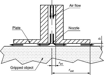
The air flowing from the central supply channel does also create a repulsive force as it is deflected in radial direction by the gripped object. Equation [7.8] gives that force.
where Fg is gripping force, Fr is repulsive force, p is ambient air density, Q is airflow, h is height of the air gap, rext is external radius of the Bernoulli gripper, and rint is internal radius of the Bernoulli gripper.
With a large air gap the air flow of the gripper is determined mainly by the flow resistance of the supply channel. The air flow is then constant with a constant supply pressure, and the gripping force increases as the gap height is decreased. At a certain small gap height the flow resistance of the air gap will dominate, and the air flow will start to decrease, reducing the gripping force. When the gap height approaches zero, the repulsive force will dominate. Therefore the gap height never becomes zero. There is thus no direct contact between the gripper and the object. This gripping principle has been demonstrated for handling fragile food like sliced cucumbers and tomatoes (Davis et al., 2006). Figure 7.12 shows a graph of typical values the sum of gripping and repulsive forces (Dini et al., 2009).

7.6.4 Lifting performance of suction grippers
The lifting force depends on the obtainable underpressure. There is a marked difference between the standard suction cup systems and the Coanda ejector grippers. The Coanda ejector may not provide enough underpressure to lift heavy objects. The Bernoulli gripper comes closer to the standard suction cup with respect to lifting capacity. The Coanda effect gripper does on the other hand work with porous and uneven surfaces for light objects due to its capacity to maintain underpressure even with a considerable air leakage through the object or along the periphery of the suction cup. Typical figures for obtainable underpressure are given in Table 7.1.
Table 7.1
Underpressure range and lifting capacity for standard, Coanda and Bernoulli suction grippers
| Gripper type | Typical underpressure range (N/m2) | Lifting force with ø90 mm suction area (N) |
| High underpressure standard ejector | 5000–80 000 | 30–500 |
| Low underpressure Coanda ejector | 500–5000 | 3–30 |
| Bernoulli gripper | 1000–8000 | 6–50 |
7.6.5 Hygienic performance of suction grippers
Hygienic issues are very relevant in most cases of handling bare foodstuff. The gripper should not introduce any risk of contamination of the product. Both materials and the gripper design play an important role.
The material used in areas that come in contact with the product should be non-toxic and hygienically approved. Stainless steel and many plastic materials are acceptable.
The most common source of contamination is residues left on the gripper from the handling of objects. These residues will lead to the growth of bacteria or fungi if they are not removed by regular cleaning. In particular, handling of bare meat will leave residues. Juices from the meat and small particles can easily aggregate in holes, grooves and the interior of the gripper. Suction grippers are vulnerable in this respect since they rely on air flowing into the gripper. Proper cleaning measures are therefore needed. Table 7.2 shows a summary of the hygienic characteristics of the three types of suction grippers.

7.7 Surface effect (freeze) grippers
One very interesting idea for hygienic gripping is to use the effect of almost instantaneous freezing that occurs when a cold body is brought into contact with a wet object. This freezing forms a surface bond by the ice formed on the interface area between the cold body and the wet object. The cold body has to have a temperature typically around -10 °C to cause this quick freezing action. The principle is in industrial use for handling small electronic component were a drop of water is added to provide moisture. A gripper for large objects was patented in 1988 (Guse et al., 1988). Although grippers of this type has been developed and demonstrated successfully in research laboratories there are no reports of these being used yet in the food industry. The main advantage of these grippers is the fact that they act single sided and can be designed to very high hygienic standards. But they also have a marked drawback in a somewhat unpredictable releasing action.
7.7.1 Design of freeze grippers
The general principle of freeze grippers comes from the fact that thermal energy flow from the surface of an object into a contacting colder surface will cool the object surface. If the object surface is wet and the gripper surface has a sufficiently low temperature there will be an immediate formation of ice in the contact area. This ice will bind the object to the gripper.
The seed of ice formation depends on the temperature of the gripper surface, the thermal capacity of both the gripper and the object and the wetting capacity of the gripper surface. The amount of moisture on the surface of fish fillets or fillets of land animals is usually enough. But pieces that have been left alone in dry areas for some time may not be moist enough for a safe grip.
The freezing process is very difficult to model. Several important parameters are usually not well known at the specific gripping instant, such as the amount of water on the surface to grip, the heat transfer coefficient and the wetting property of the gripper surface. Even a good model will not give correct answers if these parameters are not known with high accuracy.
Instead these types of grippers have been studied experimentally to obtain some information about the functional capability of this gripper family.
One of the most important function parameters is the time to form a sufficiently strong frozen film between the object and the gripper. This parameter is independent of the release methods used, but it is dependent on the type of object to be gripped. Experiments with pork meat, beef, codfish and salmon have given the empirical data in Table 7.3.
Table 7.3
Gripping attachment times and temperatures for a Peltier element freeze gripper with stainless steel gripping surface
| Contact time (s) | Grip at temperatures below (°C) | No grip at temperatures above (°C) |
| 0.2 | − 10.5 | − 8 |
| 0.4 | − 7 | − 5 |
| 1 | − 2 | − 0.5 |
Source: Lien and Gjerstad, 2008.
7.7.2 Freeze grippers with mechanical release
Freeze grippers with mechanical release have a set of smaller metallic gripping areas called freeze pads. These freeze pads are connected to a low-temperature reservoir that keeps it cold as long as necessary for a good grip. Fluid heat transfer mediums are usually applied, brine or types of fluid that stay unfrozen at temperatures below − 10 °C are used as a heat transfer medium between the gripper’s freeze surfaces and a refrigeration unit.
Figure 7.13 shows a freeze gripper with mechanical release developed by SINTEF. The freeze pads are circular areas of stainless steel that are embedded in a plastic body. They are all connected to the cooling fluid in an inner chamber of the gripper. The release mechanism consists of a stainless steel frame with a knife section that moves across the surface of the freeze pads when the frame is rotated by its mounting shaft. The shaft is rotated by a small pneumatic actuator inside the gripper body.

To obtain a gripping action the gripper’s freeze pads are pressed against the object. A film of ice is then formed immediately between the object and the freeze pads. This ice creates the holding force of the gripper.
Release is obtained by moving the release knife across the freeze pads between the surface of the pads and the object. It will then scrape the ice film off the freeze pads, thus releasing the object from the gripper.
7.7.3 Reversible heat flow grippers
The reversible heat flow gripper is built around a Peltier element which generates low temperatures on the gripper surface. The Peltier element is a semiconductor device that will generate a heat flow when an electric current passes through it. The direction of heat flow is determined by the direction of the electric current. Changing the electric current direction will also change the direction of the heat flow. This property is very useful in a freeze gripper. Freeze gripping is obtained by sending current one way through the Peltier element. Reversing the current will release the object by melting the gripping ice (Guse et al., 1988).
Figure 7.14 shows a cross section of a reversible heat flow gripper. It needs an inner chamber with a fluid that serves as a stable temperature reference for the Peltier element. Cold water is a useful fluid. It must be pumped through the gripper continuously to remove heat from the warm side of the Peltier element when the gripper is operated (Lien and Gjerstad, 2008).

Fig. 7.14 The principle of the Peltier element freeze gripper. Q0 is the heat flow from the object; Q1 is the heat flow into the cooling fluid.
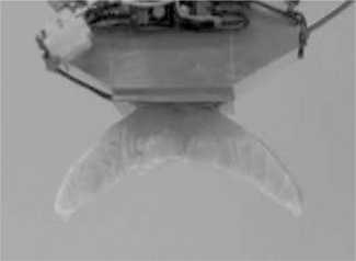
Figure 7.15 shows a reversible thermal flow gripper holding a piece of salmon fillet. The gripper has the advantage of a very clean gripping surface and no mechanical moving parts.
An alternative solution for release by reversed heat flow is to inject a small amount of steam into the frozen area. In this gripper solution a central hole is used to lead the steam into the frozen region. A slight overpressure of the steam will force it out in the gap between the gripper surface and the gripped object as the ice melts away. The freeze action of the Peltier element must be turned off during the release (Seliger et al., 2000).
The holding force of a freeze gripper is sufficient to hold pieces of meat of fish or land animals. Experiments have shown that the holding force for fish fillet is larger than the rupture force of the fish meat tissue. Experiments with gripping of textiles showed that considerable gripping force could be obtained even with only partial ice formation on the gripper face. In this experiment ice covered 10–30% of the gripper–textile contact area. The measured rupture force for the holding ice was in the range 9–15 N/cm2.
The major problem with this type of gripper is the release time. While a typical release time for a pinching gripper is in the order of 0.1–0.2 s, the Peltier element gripper with current reversal has a release time in the order of 0.5–1.0 s. The time delay challenge can be overcome though by starting the release heat flow reversal a fraction of a second before arrival at the delivery place (Lien and Gjerstad, 2008).
7.7.4 Hygienic performance of freeze grippers
The freeze grippers with mechanical release face the same hygienic challenges as the pinching grippers. There are guide ways and actuating mechanisms that have to be designed so that residue cannot collect. In particular, in the narrow gap between the knife and the freeze surface there will be a great risk of residue collection. This area has to be flushed with a cleaning fluid frequently to avoid bacteria and fungus growth.
The reversible heat flow grippers on the other hand have a much better potential for extremely hygienic operation. The gripping surface is a smooth stainless steel surface. There are no moving parts, and the housing can be made completely flat or convex to make exterior cleaning very easy.
The grippers with steam release will expel a small amount of steam through holes in the grip surface. Since steam is a very good cleaning fluid, it is self cleaning.
The Peltier element gripper has no holes in the housing facing the gripped object, no moving part and no fluid flow in the gripper action. From a hygienic viewpoint it is the perfect gripper.
7.8 Selection of the appropriate gripping technology
In any automation task the requirements for the handling of the object has to be mapped carefully to select the optimal gripper solution. In soft handling this becomes particularly important. Soft handling of food products does pose challenges with respect to mechanical handling and to hygienic operation. These challenges lead to conflicting requirement specifications. Some requirements will favour one gripping technology while others will rule out the same technology. A requirement list will then have to put weights on the different requirements in order to be able to satisfy the most important ones.
A qualitative summary of the suitability with respect to different factors of the gripper technologies mentioned in this chapter is given in Table 7.4. The table has been composed with food handling challenges in mind. The classification is crude. A + indicates that the technology works well. The sign 0 indicates neither bad nor good, while − indicates unsuitability. For some factors, such as one sided grip and precise positioning, the suitability is a go/no go issue. But for gripping on uneven surfaces the suitability may not be so clear. There is definitely a variation in unevenness. If the surface is very uneven, Coanda and freeze grippers will become unsuitable, while enclosing and long needle are suitable no matter what degree of unevenness the task presents.

7.9 Future trends: from laboratory to industry
The grippers used in robotic handling in the food industry today (2010) are mainly the traditional pinching, enclosing or suction types. These technologies work well in applications that are similar to the ones seen in other industries. But in handling tasks that are unique for food industries it seems to be more difficult to find good gripper solutions. For that reason there has been an increased effort in research laboratories to investigate new alternative gripping technologies. All the non-traditional gripping methods described in this book have been developed based on requirements related to food handling.
These new types show promising performances that can solve some of the problems that arise in robotic applications in the food industry today. One obvious problem is the hygienic challenge. The traditional gripper solutions used in industry are not the best from a hygienic perspective. The Peltier element gripper is an example of a solution to this challenge.
More important though is the capability of handling soft material in single sided grips. This is a requirement that appears quite often in discussions over automation in the processing of meat, be it fish or land animals. The softness is often paired with uneven surfaces and contours. For this class of handling problems the Peltier element gripper, the Coanda gripper and the needle grippers can provide good solutions.
But performance in laboratory tests is not enough. At this stage some users must be willing to experiment with the new technologies to determine their real value in the harsh industrial environments. This step is necessary to refine the new technologies and increase insight in gripping technology for food materials.
7.10 References
Chua, P.Y., Ilschner, T., Caldwell, D.G. Robotic manipulation of food products – an overview. Industrial Robot. 2003; 30:345–354.
Davis, S., Gray, J.O., Caldwell, D.G. An end-effector based on the Bernoulli principle for handling sliced food and vegetables. Robotic and computer integrated Manufacturing. 2006; 24(2):249–257.
Dini, G., Fantoni, G., Failli, F. Grasping leather plies by. Bernoulli grippers, CIRP Annals – Manufacturing Technology. 2009; 58(1):21–24.
Gjerstad, T.B., Lien, T.K., Buljo, J.O., Handle of non-rigid products using a compact needle gripper, Proceedings of the 39th CIRP International Seminar on Manufacturing Systems, 2006. [Ljubljana, 145–151.].
Guse, R., Koch, W., Schulz, G. Festgefriergreifer und Verfahren zu seinem Betrieben. German patent application DE 3701874 A1, 4. 1988. [August 1988].
Lien, T.K., Davis, P.G.G. A novel gripper for limp materials based on lateral. Coanda ejectors, CIRP Annals – Manufacturing Technology. 2008; 57(1):33–36.
Lien, T.K., Gjerstad, T.B. A new reversible thermal flow gripper for non-rigid products. Transactions of the North American Manufacturing Research Institution of SME. 2008; 36:565–572.
Mouri, T., Kawasaki, H., Yoshikawa, K., Takai, J., Ito, S., Anthropomorphic Robot Hand: Gifu Hand III, Proceedings of ICCAS2002. Jeonbuk, Korea, 2002:1288–1293.
Seliger, G., Stephan, J., Lange, S. Hydroadhesive gripping by using the Peltier effect. Proceedings of the ASME ‘Manufacturing Engineering Division. 11, 2000.
Thayer, N., Priya, S. Design and implementation of a dexterous anthropomorphic robotic typing (DART) hand. Smart Materials and Structures. 2011; 20:12.
Wolf, A., Steinmann, R., Schunk, H. Grippers in Motion. Berlin: Springer; 2005.