
CHAPTER 17
USE AND MISUSE CASES IN RAILWAY SYSTEMS
Ian Alexander1 and Andrew Farncombe2
1Scenario Plus, London, UK
2John Boardman Associates Limited, Southampton, UK
This chapter presents experiences with two radically different applications of scenario techniques in railway systems engineering, described separately.
A: Use Cases for Train Control Requirements Discovery
SCENARIO WORKSHOPS and interviews were used to check whether the functional requirements for a new version of a train control box were correct and complete. It quickly became clear that the described on-board functions were essentially correct, but that the requirements as written were very incomplete. The existing requirements focused on normal operations, and essentially ignored issues of testing and entry into service. By eliciting a whole-life-cycle scenario and then exploring each phase, the issues were quickly brought to the surface. These scenarios dictated the specification of a whole-journey simulator, which would otherwise have been missed, at the price of extensive delay and budget overrun. Enhancements to provide better control and easier maintenance were also agreed to be in scope.
TYPE OF PROJECT
This was a project to replace the Train Control Unit (TCU) on all the trains on a commuter railway line. Each TCU receives command codes from a safety unit. The TCU controls the speed of the train automatically. It is overridden by the safety units applying emergency braking whenever safety is threatened. The TCU is thus a safety-related (rather than a safety-critical) embedded control system.
APPLICABILITY
The approach taken did not depend on detailed knowledge of the rail environment. It could probably be applied to early requirements work—discovery and validation—in domains such as automotive, aerospace, process control, telecommunications, medical equipment, and so on. People in industry are well aware of the basic functionality of wanted systems, but may overlook ‘big picture’ issues such as how system are to be tested, brought into service, and maintained. Scenario workshops are good at surfacing such questions.
POSITION IN THE LIFE CYCLE
![]()
ROLES PLAYED BY SCENARIOS
Scenarios were used initially to check whether an existing set of requirements adequately covered the project's real needs. They achieved this by helping to discover several missing requirements, especially the need for a complete simulation environment in addition to the control box itself. This is a noticeably different focus of attention from the usual role of Use Cases to document wanted ‘system’ interactions.
STRENGTHS
Scenarios were effective in this project in helping discover situations that were not catered for by the functional requirements. Since these situations included the process of bringing the system into service, it is certain that failure to discover the additional requirements would have caused severe cost and schedule overrun.
The form of scenarios used, Cockburn Use Cases, also proved effective at documenting constraints and other detailed requirements local to specific scenarios.
WEAKNESSES
The approach and the tools supporting it worked well, but in the circumstances of an existing set of functional requirements, there were diminishing returns from scenario approaches alone. Further work was carried out with analysis techniques such as state modelling.
With the exceptions of maintainability and verifiability, scenarios did not contribute significantly to improving the quality or completeness of ‘non-functional requirements’. Both maintenance and diagnosis/test are procedural activities, and it is not surprising that a scenario approach should be helpful in those cases.
We did in fact also apply other techniques, such as a template for non-functional requirements, an online glossary linked to the requirements, and conventional requirements database attributes for requirement justification, acceptance criteria, review status, and priority. These identified and helped fill further gaps in the specifications. There was no conflict between these and the use case approach, but there was a tendency to ignore the scenarios once they had ‘done their work’ and attention shifted to conventional specifications. The project provided no support for the extreme view that scenarios are all you need for elicitation and specification.
CASE STUDY
Background
The Train Control Unit (TCU), together with the Train Safety Unit (TSU), provides Automatic Train Operation on a commuter railway. Essentially, the TSU decides if the train is safe; if all is well, it allows the TCU to drive the train.
Component obsolescence led to the need to re-engineer the TCU to extend the operational life of trains. This provided the opportunity to specify smoother and faster braking, both improving passenger comfort and enabling trains to take less time between stations. Since braking can be later, trains travel faster on average, so the capacity of the line is increased.
This situation led to a divergence of viewpoints within the railway; some stakeholders took the view that this was a simple, like-for-like replacement, while others regarded it as new equipment with capabilities that were a superset of the old system's. To some extent, this split went along discipline boundaries.
Safety engineers, for instance, were more likely to believe that since the boxes had non-identical functionality and implementation, the new and old TCUs were not ‘equivalent’ and therefore, the safety case needed to be prepared afresh.
Most people on the project took a more relaxed view. They argued that the same basic functionality would be retained, making the Safety Case easier to establish, while permitting enhanced braking. The essence of the Safety Case from their point of view is that should the enhanced braking fail, old-style braking would continue to operate; and indeed, the separate Train Safety Unit would independently trip braking in an emergency. This viewpoint depends on several pieces of argumentation:
- Systems can share a safety case if they are equivalent in function, even if different in physical implementation. (We created project dictionary definitions of two kinds of ‘equivalence’—functional and physical—to make this point less contentious.)
- The new box would be functionally equivalent to the old one, that is, the scenarios for old-style braking would be retained, even though the new implementation would probably use a modern programmable logic array in place of the discrete components in the old device.
- Since the new box would have new braking functions not demonstrated before, safety would be ensured by guaranteeing that failure of the new ‘enhanced’ braking would be independent of the old-style braking, that is, it would be argued that it was very unlikely that the additional functions could cause the old-style functions to fail. Hence, there would be a fallback position exactly equivalent functionally to that covered by the old box's Safety Case.
This kind of behaviour is normally achieved by measuring whether the enhanced system is working, that is, whether the train is decelerating along the enhanced braking rate curve in this case. If it is not, a simple switch disconnects the enhanced functionality, leaving the fallback functionality of known reliability in place. This scenario effectively calls for an independent set of accelerometers and a switching device to control whether enhanced braking is to be overridden by fallback braking.
A second level of protection can be provided by incorporating a watchdog process that repeatedly checks that the processor responds normally; if the processor does not respond within a time-out period, it is assumed to have failed and emergency braking is applied (before the train actually passes a signal at danger and trips emergency braking that way).
The old specifications were incomplete, so an approach was selected to bridge gaps in the specifications to support a low-risk, ‘right-first-time’ procurement of the replacement unit. For example, the old specifications covered the system's behaviour with respect to the train's speed and track codes in detail, but did not cover issues of verification during development and maintenance; nor did they state explicitly the non-functional requirements such as reliability or conformance to existing interfaces.
METHODS AND TOOLS
Our basic approach was to run a series of workshops and interviews to elicit scenarios. We then organised the scenarios into Cockburn-style Use Cases with tool support, and played them back to the domain experts to validate them (Cockburn 2001).
The project managed its specifications with a combination of Microsoft Word and Telelogic DOORS, currently the market-leading requirements management tool. To enable DOORS to represent scenarios, we also installed Scenario Plus for Use Cases. This is an add-on that supports the capture, documentation, analysis, diagramming, navigation, and export as hypertext of Cockburn-style use cases (Scenario Plus 2003, Cockburn 2001) (Figure 17.1).
APPROACH
A series of workshops and interviews was held with railway experts to identify the stakeholders' viewpoints. The first workshop established that there was a need for a coherent set of scenarios to give an end-to-end overview of the system's context and required capabilities, and sketched out the shape of the largest scale scenarios involving the TCU.
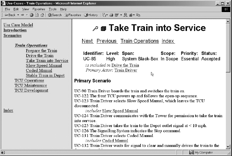
FIGURE 17.1 Use case model exported as a hypertext
Subsequent workshops discussed and agreed on operational scenarios not only for normal TCU operations but also for the testing, maintenance, and manual modes that had been omitted.
The scenario workshops discovered a key group of requirements for a Simulator, which would have been costly to add further downstream. Essentially, since the available track is in constant use, on-track test time is a scarce resource; new systems must be ‘right first time’. Simulation must therefore cover not only the interfaces to the box, but must behave as if the box was in a train travelling the whole track, each station approach being unique.
The existing (partial) specifications were imported from Microsoft Word into the requirements tool. Attributes (database fields) were created to document test criteria, justifications, and other details not previously covered given the limitations of ordinary word-processed project documents.
The Specifications for the TCU, the Simulator, and other Test Equipment were checked against the use that would be made of these devices as described in the Scenarios.
The scenario structure consisted of operational goals (e.g. ‘Drive the Train’) and the sequences of steps these entailed. Additional information such as alternative possibilities within a scenario, exception conditions, the user roles involved, and any constraints (e.g. performance, braking accuracy, etc.) were developed and added in a systematic way.
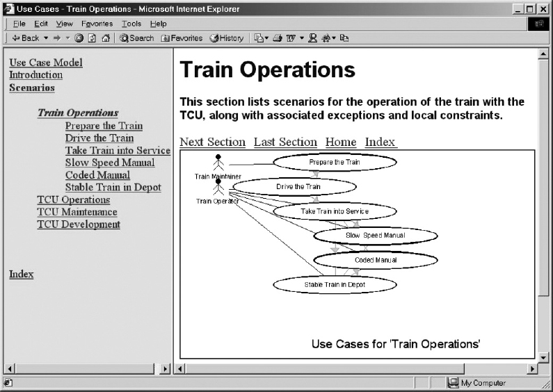
FIGURE 17.2 Navigable diagrams and table of contents
Results were exported as fully navigable hypertext available to the project team through a standard Web browser. Use Case diagrams were image-mapped to make the Use Case bubbles clickable; an equivalent hierarchical table of contents was constructed in text (Figure 17.2). This meant that no access to DOORS or skill in using it was required to review the scenarios.
A template of headings (similar to Appendix 1–4, NFR Template) was created to organise the system's non-functional requirements, including reliability, maintainability, physical and environmental constraints, and interfaces. Surprisingly, this led quite naturally to the identification of several more functional requirements, seen to be necessary to make the system maintainable. In other words, a template approach helpfully complemented the use of scenarios in discovering requirements.
LESSONS LEARNT
Scenarios are not necessarily better at defining the detailed functionality of a system than traditional requirements supported by suitable behaviour models (though Alistair Mavin describes a use of scenarios, persisting throughout the specification and design of another railway system in Chapter 20, alongside other modelling techniques). Once we had shown that scenarios were beneficial, some of the engineers involved displayed a tendency to try to force all the requirements into scenario form, in our view, to little benefit.
Other approaches that we used, including the use of a template (a hierarchy) of nonfunctional requirements, and a project glossary linked to the requirements, also helped to discover requirements and to clarify their meanings. Scenarios are useful but they need to be combined with other approaches, some of which are quite traditional.
The form of scenarios used, Cockburn Use Cases (Cockburn 2001), to some degree expects that there are human roles for each case, but in this instance most of the system's behaviour is automatic with little direct human involvement. It is sensible to be quite flexible about the amount of detail required for a use case; sometimes it helps to fill in a fully dressed template; sometimes a bare story is enough.
Some skill in facilitation was required initially for the workshops, given a team unused to such methods. A dogmatic or mechanical approach would not have worked.
Tool support worked perfectly in technical terms, but the human issues of getting busy engineers to take advantage of technology, rather than to simply continue working with familiar word-processed documents should not be underestimated. Under time pressure, people have a strong tendency to go back to the familiar—unless there are stronger reasons for using the new tools.
Overall, scenarios more than paid for themselves on this project, but most of the benefit was obtained quite quickly, with diminishing returns thereafter. Early gains do not necessarily imply much more benefit to come.
KEYWORDS
Use Case
Scenario
Control System
Railway
Requirements Discovery
Hypertext
B: Misuse Cases for a Seats Trade-Off
MISUSE CASES were applied to analyse Trade-Offs of design options against requirements for the construction of seats and armrests on a commuter railway.
In a Trade-Off workshop, a diagram was constructed showing Use Cases for goals held by system designers, and Misuse Cases for goals held by hostile agents. Relationships between these goals were elicited and documented on the diagram.
It seemed helpful to devise a simple set of relationships, specially suited to TradeOff analysis: ‘threatens’, ‘mitigates’, ‘aggravates’, and ‘conflicts with’, to be used with the ordinary ‘includes’. The result is an easily appreciated diagram that makes clear to non-technical stakeholders such as railway maintenance engineers, managers, and seat designers how their requirements may conflict in the design domain. This clarity contributed to the success of the Trade-Off workshop.
TYPE OF PROJECT
Low-technology structural design complicated by previously unresolved stakeholder issues.
APPLICABILITY
This simple approach could be helpful in unravelling a range of stakeholder conflicts and design trade-offs in different settings.
POSITION IN THE LIFE CYCLE
![]()
ROLES PLAYED BY SCENARIOS
Misuse Cases (see Chapter 7)
STRENGTHS
- The approach is simple and direct.
- The resulting diagrams are easy to understand intuitively.
- Just acknowledging issues is often enough to avert conflict.
WEAKNESSES
- The approach is essentially human and qualitative, so it is not suitable for complex risk-based trade-offs that should be handled with quantitative methods such as linear programming or Monte Carlo simulation.
- Diagrams can become cluttered if there are many interacting factors, though tool support can effectively mitigate this problem.
CASE STUDY
Scenarios can be helpful not only with difficult-looking problems in software and advanced systems, but with many apparently simple problems that lack software altogether. We were recently consulted by a railway company about the safety and comfort of the seats in their commuter trains (Figure 17.3). What looked at first like a trivial problem, turned out to be remarkably complex. This section presents part of the analysis of the requirements and design issues on the seats. It was a contribution to a participative workshop approach for a whole-day meeting of about 20 stakeholders from the railway company, including project management, design engineers, maintenance engineers, and quality assurance representatives.
The engineers on the seats project made it clear that they felt stuck, as long-standing discussions had reached deadlock. They were aware that there was a problem, but had not progressed beyond recording that different people in the company held differing views on the situation. Crucially, it appeared that Maintenance had not been involved in the discussions.
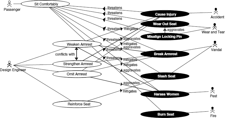
A suitable starting point for the workshop was the passenger's top-level goal for his or her seat, namely to sit comfortably and safely. This was threatened by numerous hostile agents, who adopted a variety of strategies. These are shown as Misuse Cases (see Chapter 7) in Figure 17.4, with threat arrows directed at the top-level goal. Some of the agents were literally hostile: Vandals armed with knives might slash seat covers; ‘Pests’ might seat themselves next to women, especially in seats that lacked dividing ‘armrests’. Other metaphorically hostile agents included natural causes such as Fire, and Wear and Tear, or accidents like coffee or soft drinks being spilt on to seats, and trickling through the supposedly watertight box lid into the electronics below; engineers need not limit their thinking to literally hostile human agents.
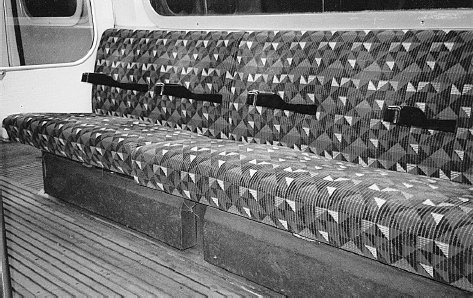
FIGURE 17.3 Example seating on a commuter train The illustration shows a different solution from the one discussed; in particular, high-level armrests are in place, fixed at a single point
Even apparently simple Misuse Cases like normal Wear and Tear of seats could be aggravated by design choices. The seat was locked into the sitting position after maintenance by an upward-pointing locking pin that was supposed to engage with a downward-opening bush on the underside of the seat. Unfortunately, this pin could be misaligned by maintenance staff, especially once it had started to wear and had some play in its mounting, and then protruded into the foam of the seat. This considerably aggravated the wear and tear on the seat caused by passenger movements.
The design engineers in the railway had considered various stratagems to mitigate these threats. They had become bogged down because they had found no clear way ahead: some of the proposed (and actually implemented) solutions aggravated some of the threats or conflicted with each other.
For example, the armrest had some years earlier been intentionally weakened so that in the event of a passenger being thrown against an armrest during an emergency stop, the armrest would snap off cleanly (‘be frangible’) at its base rather than cause injury to the passenger's abdomen. The railway company was aware of several problems that had been aggravated by this design change:
- Vandals found it easier to break off the armrest intentionally, and the broken-off armrest formed an all-too-convenient weapon in the hands of such people.
- The absence of an armrest—whether because it had been removed for safety or broken off—made female passengers uncomfortable as it increased the nuisance from ‘pests’.
- It reduced passenger comfort more generally, as in an undivided space, neighbours seem nearer and people accidentally sit on each others' coats, and so on.
- The armrest was the only thing that maintenance engineers could hold on to, to lower the seat down to the locked (sitting) position after replacing the seat cover or accessing electronics subsystems in the boxes beneath the seats. It had been assumed that since armrests were mandatory, no other handgrip was required. Without any way of controlling the lowering of the 30-kilogram seat, it was allowed to fall, aggravating the wear and tear on the locking mechanism, and possibly presenting an increased risk of injury to maintenance staff.
FIGURE 17.4 Misuse case-based trade-off analysis of railway seat issues (‘includes’ relationships omitted for clarity); normally presented in stages (see Figure 17.6)
The armrest was thus revealed to have numerous functions and to be safety related; its function was not just to provide a place for passengers to rest their arms.
The simplest solution perceived by the railway engineers was to strengthen the armrest, accepting the risk of injury this might cause. However, there was no agreement on this approach: there was evidently a conflict between the design goals of strengthening and weakening the armrest. For example, some engineers felt that a strengthened armrest could lead to structural damage to the seat frame itself in the event of a determined vandal attack, given a strong armrest firmly attached to the seat frame, and offering plenty of leverage. This would greatly increase the cost of an episode of armrest vandalism.
The undesired effects of weakening the armrest had not been considered when the decision to make the armrest frangible had been taken. It appears, therefore, that vandalism threats had not been taken into account in the decision-making process, despite the familiarity of vandalism to railway maintenance staff who daily make good a wide range of all kinds of deliberate damage, including graffiti, torn seat covers, burns, and breakages.
This suggests that stakeholders such as train maintainers had not been adequately involved in earlier decisions. In fact, one of the ‘aha!’ moments in the workshop occurred when the project managers and systems engineers present realised that maintainers had an important voice; the meeting tangibly relaxed as soon as the maintenance chief had explained his viewpoint.
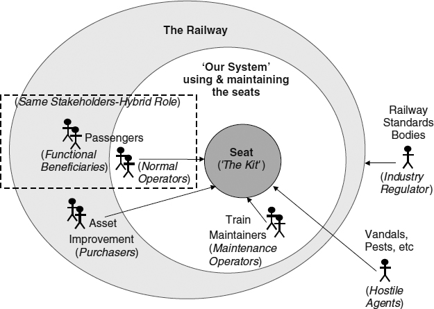
FIGURE 17.5 Onion diagram of train seat stakeholders
In general, inadequate attention to system scope leads to difficulties during system operations and maintenance. The scope of the train seat design is not passenger + seat, but includes the maintenance of the seat and the other scenarios already described. It is essential that the scenarios span the full range of the domain, and (as a corollary of that) that the viewpoints of all the stakeholders are considered. The Onion Diagram (Figure 17.5: see description in Chapter 1, under Stakeholders) shows that despite the apparent triviality of the problem—after all, ‘using’ the seat does not require an Operations Manual—the system of seats, people, maintenance procedures, and standards is wider than you might expect. In fact, the key role in daily use of the system is clearly seen from the diagram to be that of the train maintainers.
These and similar arguments were expressed simply and naturally in diagrammatic form with Misuse Cases, using the additional relationships ‘aggravates’ and ‘conflicts with’ already mentioned. The diagram was introduced in stages, presenting first the top-level goal and actors, then the Use Cases for the subsidiary goals, then the hostile actors and the seven Misuse Cases threatening the goals, and finally (with differently coloured arrows) the analysis of mitigations, aggravations and conflicts.
The Scenario Plus toolkit for Use/Misuse Case modelling makes such piece-by-piece presentation simple, by providing special-to-purpose filtering tools (Scenario Plus 2003) (Figure 17.6).
None of the stakeholders in the workshop challenged this analysis, though it was pointed out to them that the diagram was incomplete. Evidently, once the conflicts, threats, and aggravations were explicitly stated, much of the heat and confusion was taken out of the analysis. Further, the simple act of inviting the different stakeholders to a workshop itself made clear that different viewpoints could rightfully exist.

FIGURE 17.6 Special-to-purpose relationship filtering tool
Faced with the challenge of resolving the problem with the armrest, the design engineers quickly pointed out that they could rethink the design of the armrest: it could be made strong, low, and curved, difficult to vandalise, protecting passengers and frustrating pests. They sketched a rough outline of a new ‘armrest’—it had in effect become something new, something like a ‘non-frangible vandal-resistant armrest/separator’—and promised full drawings for a week later. The sketch (Figure 17.7) is similar to what they drew.
As another example, the design engineers had previously considered that the seat-locking pin had to face upwards for two reasons.
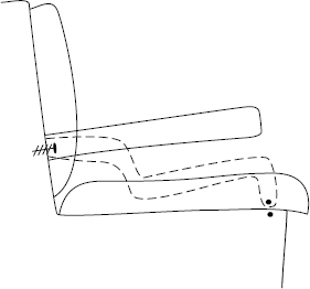
FIGURE 17.7 Sketch of old (solid) and new (dashed) armrest options
- There was no room for a locking mechanism below the seat: electrical equipment was housed in the boxes under the passenger seats.
- Since the equipment was electrical, the box lids had to be watertight, so that fluid such as a spilt drink could not cause a short-circuit.
However, the stakeholders in the workshop quickly ascertained by discussion amongst themselves that these fears were groundless; a simple blind-ended metal bush could be mounted in the box lid, requiring only a few millimetres of extra space, and offering no path for liquids to penetrate, so the locking pin could point downwards. There would then be nothing pointing upwards that could get misaligned and destroy the foam padding of the seat.
The Trade-Off Analysis had brought together the relevant facts for several interrelated issues, enabling the design to be reconsidered objectively in the light of the system requirements. Misuse Cases thus have a definite role in clarifying the interplay of system requirements and design, and indeed in addressing design issues and Trade-Offs during in-service operations and maintenance.
LESSONS LEARNT
In the examples discussed in detail—the armrest and the locking pin Trade-Offs—the problems were resolved by the combined domain knowledge and skill of the stakeholders, once the interactions (threats, mitigations, conflicts, aggravations) had been brought to their attention. The contribution made by consultancy, facilitation, and analysis techniques was purely to enable this resource of skill to be brought to bear on the problems.
Tool support is not essential for documenting and presenting such analyses, but it can be helpful. The Scenario Plus toolkit's Misuse Case and Trade-Off facilities proved to be effective in the railway case: the filters allow different types of relationship to be presented separately or together, so the presentation of threats, mitigations, and conflicts could be built up visually in stages, in a way that the stakeholders could understand.
Using any suitable tool encourages people to record the reasons for a design decision. A Trade-Off Analysis diagram automatically records much of the thinking embodied in a Trade-Off workshop. Scenario Plus also makes it easier to keep diagrams up to date. But more importantly, integration with an industrial-strength requirements engine, as with Scenario Plus' DOORS platform, enables design elements and tests to be traced back to (Use Case) requirements and (Misuse Case) justifications and Trade-Off arguments.
There are clear advantages in recording the justification for design decisions made in the presence of possibly conflicting viewpoints. If the reasons for a decision are not adequately documented and agreed, there is a danger of continual disputes in line with the shifting political fortunes of different stakeholder groups within an organisation. This can cause indefinite oscillation between conflicting outcomes (‘paralysis by analysis’). Alternatively, if decisions are not discussed openly, they may be made excessively autocratically without adequate consideration. This can lead to shock discoveries of problems after decisions have been implemented. Trade-Off analysis, in contrast, provides a thorough cycle of stakeholder involvement, and leads to a shared and lasting decision. Simple graphics such as those illustrated here, which help people share their understanding of Trade-Offs, can contribute to this success.
To use a Misuse Case model in a workshop, it is obviously easiest if you can prepare a reasonably good model in advance using interview notes from one or two key stakeholders—this is what was done for the seats workshop. The facilitator then introduces the modelling approach and the model itself, explaining that the model is incomplete, and that participants are welcome to suggest additional items.
Scenario Plus makes it possible to edit quickly enough for an analyst to update a model while a facilitator obtains inputs from workshop participants using a whiteboard or flipcharts. This means that you can acknowledge a stakeholder's contribution by modifying the model, provided you don't divert stakeholders' attention from the workshop's business—analysing Trade-Offs—to optimising the model visually.
If you intend to create a model during a workshop, you certainly need a team of two people to manage simultaneous facilitation and modelling.
Whenever you build your model, you should allow opportunities for stakeholders to comment on the model, so that you can refine it with them. The essential thing is that the stakeholders should feel that the model describes their situation adequately.
Was the approach the right one? Without Misuse Cases, the seats workshop might still have been successful, but participants would have been less focussed on the nature of the conflicting forces. The workshop would probably have spent longer trying to analyse the existing situation. This might have put pressure on participants to reach a solution quickly. That is always unwise in a workshop as different participants work at different speeds, and people need time to express themselves, even if it is only to agree with what others are suggesting.
What benefit did identifying threats (as Misuse Cases) bring? It helped participants acknowledge that there were explicit choices confronting the design engineers, and that the approaches that had been thought of before the workshop were all problematic. Indeed, the temporary solution that had in fact been adopted, namely, removal of the armrests, was actually illegal. The Misuse Case model helped get the whole workshop to acknowledge that no pre-existing solution was acceptable and unproblematic. At that point, the workshop rapidly moved into a free space in which it could think creatively. It isn't easy to think of ways of measuring this effect, though with hindsight participants could have been asked to fill in feedback forms on the advantages and problems posed by the conflict analysis approach.
SUMMARY
This chapter has presented two quite different examples of railway projects in which scenario use, combined with other analyses and consultancy approaches, helped improve the quality of the systems engineering, and perhaps contributed to the safety, efficiency, and comfort of railway operations. As the conceptual tools used were quite independent of the domain, there seems every reason to believe that similar benefits could be gained by applying the same techniques elsewhere.
KEYWORDS
Railway
Design Trade-Off
Misuse Case
REFERENCES
Cockburn, A., Writing Effective Use Cases, Addison-Wesley, 2001.
Telelogic DOORS website, 2003, http://www.telelogic.com
Scenario Plus website, 2003, http://www.scenarioplus.org.uk