
CHAPTER 12
USE CASE-BASED SOFTWARE DEVELOPMENT
Peter Haumer
IBM Rational Software, Schipol-Rijk, Netherlands
USE CASE authors have the difficult task of writing specifications for many different audiences. They have to balance the language, content, and style of their use cases for the needs of both non-technical and technical stakeholders. While most chapters in this book focus on non-technical stakeholders such as customers and users, this chapter discusses the developer as another important audience of use cases. To write use cases that are also useful to developers, analysts have to understand what developers will use them for. The difficulty is, of course, to keep the balance for the other audiences without negating the main benefit of use cases: facilitating interdisciplinary communication of requirements.
I will outline in this chapter the role Use Cases play for Object-Oriented Analysis and Design (OOAD) as described in the Rational Unified Process (RUP 2003). I will begin by discussing the particular properties use cases possess that make them such a good tool for requirements management as well as for guiding software design. I will define additional concepts required for these tasks. Finally, I will walk you through a core set of analysis and design activities, examining the role use cases play for these activities, using examples from a web-based e-commerce application.
APPLICABILITY
- Projects with interdisciplinary team communication.
- Projects utilising object technology and software design frameworks (e.g. J2EE, .NET).
- Wide range of software and systems-engineering projects in terms of scale from small web-based e-business applications via business process engineering projects to large-scale systems-engineering projects (the latter two applying a use case flow-down between systems and sub-systems not discussed in this chapter; see Cantor 2003, RUP SE 2003 for more details).
POSITION IN THE LIFE CYCLE
![]()
KEY FEATURES
- Industry leading software development process.
- Iterative, risk- and use case-driven analysis and design methodology.
- Full traceability from requirements to analysis to design to code.
- Augments requirements with user experience modelling to improve communication on requirements and designs.
- Facilitates predictable and repeatable iterative development through analysis and design mechanism and trace-based impact assessment.
- Extensive tool support available (not discussed here).
STRENGTHS
- Use cases present requirements in context improving communication within interdisciplinary teams by focusing on delivering actor value and not technical detail.
- Use cases relate to stakeholder goals, which facilitate prioritisation and planning of iterative development (implementing high priority and risky requirements first).
- RUP OOAD defines well-understood and scalable process of transforming requirements into software solutions.
- RUP OOAD systematically established traceability as part of the primary activities to support iterative development as well as change impact-assessment and management.
WEAKNESSES
- Reading and understanding use cases should be easy for any stakeholder. However, modelling and writing use cases that they are easily understood as well as successfully used for analysis and design requires a well-trained system analyst and designer.
- As a result, experience is required to avoid typical pitfalls when adopting use cases and OOAD. Pitfalls include functional decomposition of use cases, overanalysis of use cases and analysis models, giving too much or too little detail in use cases, mixing requirements and design, not using the right amount of analysis and modelling to abstract from design decisions in the right places, not enforcing design mechanisms in the teams to incorporate design decisions systematically, etc.
- RUP OOAD also requires an architect with solid methodological as well as technical understanding leading the design with experience, vision, and creativity.
TECHNIQUE AND WORKED EXAMPLE
The Use Case – Centred Requirements Framework
I will start this chapter by listing and defining the key elements a designer needs to be provided with to do OOAD, that is, the inputs to this discipline of software engineering.
Goals and Requirements
First off, let's talk about requirements and goals in general (just to avoid any misunderstandings with other sources and definitions of these terms):
A solution addresses goals stakeholders1 have in respect to their environment, for example, the goal to achieve or to improve something.
The goal allows stakeholders to express their needs for their world or application domain (e.g. their business, their automation environment, etc.) for which a solution or an improvement to an existing solution can be defined with requirements. Requirements address or realise the solution-independent goals with concrete solution specifications. An example goal:
“Provide automated order handling.”
An example of one of the requirements addressing this goal:
“The sales system displays the types of available order transactions. The customer selects a transaction type. The sales web displays the list of books that the customer currently has pending.”
You can see that many different solutions for a given goal can be found: this example goal could have also been addressed with a phone line utilising touch-tone codes or speech recognition requiring quite different set of input-output interactions. The mapping of goals to high-level requirements that have been scoped to be part of a project, which is establishing the solution, is documented in what the RUP calls a Vision Document (RUP 2003).
System Boundaries
On the basis of these definitions, it is not possible to write requirements without exactly knowing what the system boundary is going to be. Certainly, in early phases of a project when the boundary of the system is not clearly defined, yet, all kinds of information will be gathered from stakeholders about what needs to be achieved and done by a potential solution. However, until the boundary is defined, we will call these stakeholder requests. Once, the boundary is defined one can then map stakeholder requests to goals, requirements, or statements about the design.
The notion of system boundary plays an important role for organising our specifications especially in the case of projects in which a system is going to be established that is actually decomposed into more than one sub-system. The (RUP SE 2003) defines a system as follows:
A system, which may contain hardware (computational and non-computational), software and human workers, delivers some needed operational capability to its users. A system is composed of sub-systems, which collaborate to yield the behaviour and characteristics of the system.
Therefore, to scale systems development you need a separate requirements specification for every sub-system, because it could be outsourced to another development team, might involve teams with completely different skill sets, and must be tested separately. If you regard every system as a box for which you produce a black-box requirements specification, you could depict a decomposed system as in Figure 12.1 below.
This simple example shows three levels of decomposed systems of three different kinds:
- A business system, that is, a business environment for business workers, for which the black box perspective comprises the services that the business has to offer to its customers (also often referred to as Business Processes).
- A software system that is installed and operated by business workers as well as other systems as part of the business realisation.
- A composition of the software system in software sub-systems (the realisations of which are also often referred to as Software Components).
Again, for all of these levels you specify requirements in terms of the functionality provided by the system's interfaces as well as qualities (also often referred to as NonFunctional Requirements) such as usability, reliability, performance, and so on. Needless to say that a real system (think of a whole financial institution) might involve many more levels including hardware with embedded software, business units or departments as sub-systems of the business.
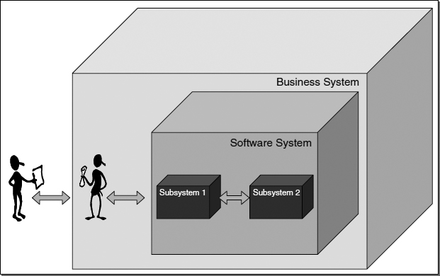
FIGURE 12.1 A decomposed system
Use Cases
Now, we are finally ready to talk about how the interfaces between the boxes and their users (called Actors) of Figure 12.1 should be specified, which leads us to the definition of, in respect to this book, the most import concept:
A use case defines a sequence of actions a system performs that yields an observable result of value to a particular actor.
In other words, a use case describes primarily functional but also non-functional requirements from the perspective of an actor achieving particular goals. In contrast to more classical styles of specifying requirements, use cases define clusters of requirements based on goals; that is, a use case groups together all requirements for a solution to achieve one or more particular stakeholder goals.
Because there is always a many-to-many relationship between goals and requirements, you as System Analysts have to decide which goals of the overall goal set defined for a project you are going to use to derive the use cases from. Your general guideline would be to check if your use cases communicate the most important actor goals that will be addressed by the system, that is, the goals you can use to “sell” your system to stakeholders. The trick that makes use cases such a successful interdisciplinary requirements elicitation and validation technique, is the idea of present stakeholders what they are primarily interested in: their customers' or their own goals, rather than grouping and presenting requirements based on some technical criteria or the solution's components or structure. As expressed in Beyer et al. 1997, in contrast to technology experts who know and “like” technology, stakeholders tend to merely want to get their jobs done, and accordingly want computers to be as invisible as a pen's ballpoint so they can focus on their tasks.
As such, use cases cannot be decomposed into sub-units. They represent one unit of addressing needs or goals. Functional decomposition is a matter of Analysis that I describe in the section titled ‘Object-Oriented Analysis with Use Cases’, using completely different concepts. Always remember, working with use cases is synthesis, not analysis. You do not break a use case apart like problems that are decomposed into smaller problems following a divide and conquer strategy. A use case describes a solution, synthesising all the interactions necessary to achieve the goal expressed in its name. Bittner and Spence (2003) convey this by saying that a use case provides you with a complete experience that result in real value for at least one actor. If you need to link use cases together in order to provide value, your use cases degrade into hard to validate context-free functions and those high-level use cases you use to link them together degrade into empty shells.
Use Case Diagrams
Use case specifications are made up of graphical and textual parts. Let's have a look at an example of a graphical UML use case representation.
Figure 12.2 depicts use cases, in a UML use case diagram, for an online sales software system from the actor Buyer's perspective. Typical goals of buyers for online shopping are to browse a catalogue, maintain their shopping cart, check out their orders, review past orders, and so on. As you can see in Figure 12.2 use case names are chosen to exactly express these goals. You can also see that use cases can depend on each other as the Check Out use case depends on the Authenticate use case. Modelling these dependencies smells of functional decomposition, so use case relationships should be used only when absolutely necessary. Using them heavily makes specifications confusing and hard to read. In Figure 12.2, the ![]() include
include![]() -dependency addresses two issues,
-dependency addresses two issues,
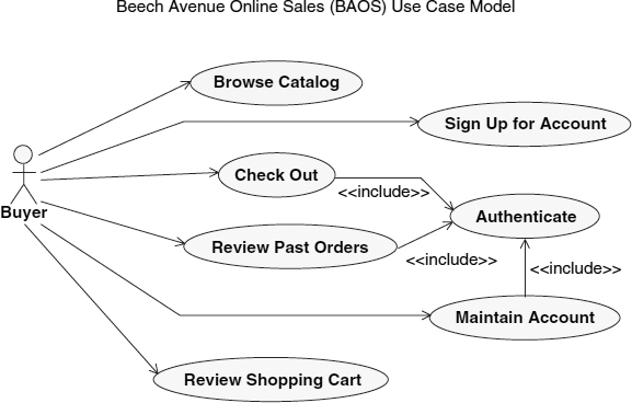
FIGURE 12.2 A use case diagram
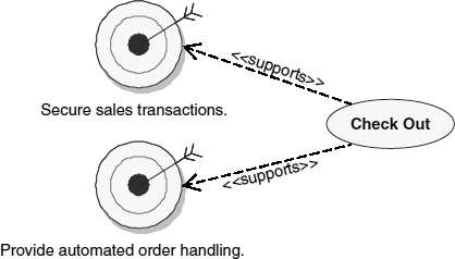
FIGURE 12.3 Goals addressed by “Check Out” use case
- (a)you want to communicate the authentication goal to stakeholders saying that certain activities are only allowed to be performed after2 the actor has been properly authenticated and
- (b)you want to reduce complexity in the textual part of the use case specifications by avoiding that authentication activities have to be described three times, that is, in the specification of “Check Out”, “View Last Orders”, and “Maintain Account”.
Let's take one more paragraph to clarify the difference between goals and use cases. A use case is solution/system boundary specific. Its name is derived from a related goal. The use case's textual representation shows the concrete requirements necessary to achieve the goal the use case name relates to. A use case can be related to many other goals identified for a particular development project. Figure 12.3 shows an example of use case “Check Out” addressing or supporting different other goals3 especially goals of a more non-functional or quality character that are sometimes also called softgoals (Yu 1997).
Use Case Specifications
The graphical use case representation only presents an overview to your requirements. You always have to combine it with the textual representation of use cases that describes input–output scenarios with all their possible variants and exceptions, as well possible structural requirements (i.e. data), business rules, and non-functional requirements that directly apply to the use case. In cases where the non-functional requirements, rules, and data are of a more general nature and/or apply to more than one use case, these requirements are then typically factored into separate supplementary specifications (RUP 2003) and are not part of a use case specification.
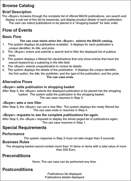
Figure 12.4 is an example use case specification for “Browse Catalog” from Figure 12.2. It had to be simplified for space reasons, but it contains the most salient aspects of a use case spec. Surely, there will be many more alternatives and special requirements you can think of, which have to be added. Also, the alternatives should be structured using numbers for each step.
However, this small example already shows key features of use cases. First off, the use case presents requirements in context. Instead of listing isolated statements of system requirements, the use cases package requirements in stories, so-called Flows, which make up the Flow of Events.
A Flow is a description of a partial path through the use case description. The Flow of Events describes the entire set of use case flows.
The Basic Flow describes the simplest and most straightforward way possible to achieve the use case's observable value. An Alternative Flow, as the name suggests, relates an alternative flow to the basic flow. They should always be written in a style that indicates
- (a) to what step in the basic or any other alternative flow they relate to,
- (b) under what condition or based on what event this alternative would be chosen,
- (c) enumerating the steps that are different from the basic or other alternative flow they relate to, and
- (d) where in the basic or other alternative flow the events would resume afterwards.
The flow of events makes up the complete picture of all possible behaviour the system supports. Particular flows can then be combined into scenarios that represent exactly one path through the flows, helping to explore one concrete case covered by the use case at a time. Scenarios are not explicitly represented in a use case spec, but can be derived from it.
A Scenario is a specific instance or occurrence of a use case flow of events.
Applying Use Cases
In conclusion, you can say that use cases group together all possible stories that put system requirements in logical sequences describing how to achieve (and even not achieve) a goal. As you will partly see in subsequent sections, this is not only important for requirements elicitation and validation—to set focus and to establish a context enabling stakeholders to understand the requirements better—but also for many other disciplines of software engineering (see also Kruchten 2000, Kroll and Kruchten 2003).
- Project planning and management: Use cases help you to scope your project, that is, deciding on priorities of requirements and change requests, by discussing values and goals addressed by the use cases. You also use the priorities to plan and assess iterative development activities of the flows of your use cases (see Royce 1998). Realising use case flows as milestones of iterations ensures that at any time all milestones result into a system that delivers value to stakeholders for their review.
FIGURE 12.4 Use case specification for “Browse Catalog”
- Analysis and design: Will be discussed in the next sections.
- Testing: Use cases allow you to systematically derive test cases from the requirements by means of analysing use case scenarios and finding representative sets of input values for the conditions of alternative flows (see Heumann 2001 and Chapter 14, Use Cases, Test Cases by Ian Alexander).
- Documentation: If you look at how today's manuals and online help are organised, you see that they are structured based on what a user wants to achieve with the software. If I look, for instance, at the online help of the text processor I used to write this chapter, I see sections such as “Creating a document”, “Moving around in documents”, “Automatically correct text as you type”, and so on. I am not saying that you should copy-and-paste your use cases to get to your online documentation, but that use cases serve as an excellent starting point for the organisational structure of your documentation. Moreover, if you see other forms of documentation delivered for software these days: a tutorial is a collection of use case scenarios demonstrating the key values of the software to the user.
A more complete introduction to use cases for requirements management and especially use case writing would be out of the scope of this chapter. However, I will get back to the use case of Figure 12.4 discussing its structure and contents in the context of performing its analysis and design in subsequent sections. See Bittner and Spence (2003) for an excellent textbook on use case modelling and writing.
Object-Oriented Analysis with Use Cases
In this section, I describe the activities to systematically create software system analysis and design models from a use case specification. As described above, we take prioritised flows of use cases as separate units of analysis, design, and implementation in iterative development to ensure that the system we construct iteratively provides the important goals first—especially when they are associated with technical risks—before we deal with the less important ones (Kruchten 2000, Kroll and Kruchten 2003). You will see that certain use case characteristics and styles directly support analysis and design. The focus for the following sections is to look at the role use cases play for analysis and design. This chapter cannot provide a detailed introduction into object-oriented analysis and design; see instead Jacobson et al. (1998), Conallen (2002), Eeles et al. (2002), RUP (2003). For recent developments in Jacobson's thinking on Use Cases, see Jacobson (2003a) and Jacobson (2003b).
The goal of object-oriented use case analysis and design is to transform the “black box” use case specifications into a “white box” use case realisations.
A use case realisation describes how a particular use case is realised within the analysis and/or design model, in terms of classes and collaborations between these classes that exactly support the behaviour specified in the use cases.
Whereas an analysis model represents essential and technology-independent abstractions of the solution focusing on concepts of the business domain and the behaviour specified in the use cases, the design model includes concrete technology and design decisions representing an abstraction of the implementation. Its models comprise abstraction of concrete technology such as a J2EE session bean components or .NET Active Server pages. Whereas working on the analysis model has an emphasis on functional requirements (“getting the behaviour right”), the design model also systematically deals with non-functional requirements (“getting the quality right”4) on top of the functional requirements.
UML Representation of Use Case Interactions
So, how would you get started transforming our use case from Figure 12.4 into a use case realisation? A common starting point is to systematically explore the information contained in the use case and to project this information onto conceptual representations.
You can see an example of such a representation in Figure 12.5. It shows a UML sequence diagram for our use case's black box interactions between actor and system. Each pair of messages represents one round trip of events in which the actor provides a stimulus or input and gets a response or output back from the system. The use case text has been used to annotate these round trips, which makes the diagram a so-called scripted sequence diagram. Because these round trips of events denoted in the diagram play an important role for many design decisions later on, use case authors often write their flow of events with such a diagram in mind. You see from the diagram's script that every numbered step in my use case also maps to such a round trip in Figure 12.5.
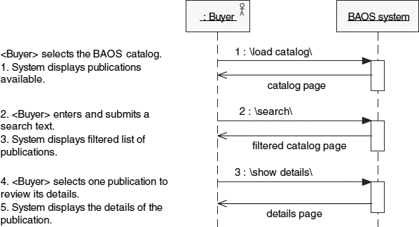
FIGURE 12.5 Scripted sequence diagram showing black box specification of “Browse Catalog” use case
User Experience Modelling
Just to provide you with one example of how this structure supports design decisions, let's have a look at the user experience model in Figure 12.6, also directly derived from the use case's flow of events. This type of model is particularly popular in web development projects.
The User-Experience (UX) Model describes the user-experience elements of the system (the screens and input forms), the dynamic content that appears on the elements, and how the user navigates through the elements to execute the system functionality.
For a detailed introduction to UX Modelling see (Conallen 2002, RUP 2003). How concrete should use cases be? There is a dilemma here,
- Many development teams decide that their use cases have to be kept general enough to be realised with different UI design paradigms;
- but also concrete enough to provide all essential requirements (e.g. inputs, outputs, business rules, and quality) for the application design.
Teams often create and maintain a separate user experience model in conjunction with use cases as well as screen mock-ups. Such a model is (still) a black box representation of the system helping to improve
- (a) stakeholders' understanding of requirements, making the system specification more tangible with a concrete flow of screens and
- (b) the conceptual design of consistent screen and navigation flows for the application's user interface (UI).
The idea here is to separate UI design from requirements, but also to use these in synergy to improve requirements and UI design as well as consistency.
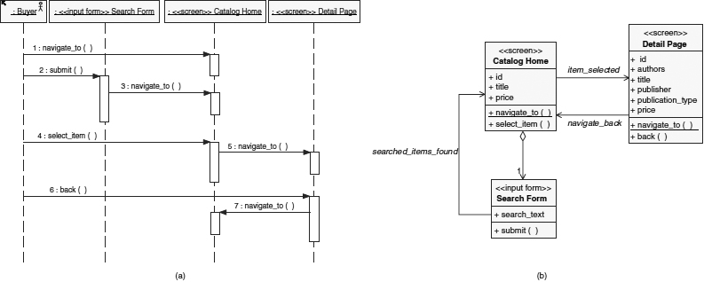
FIGURE 12.6 A user experience model. a. Use case storyboard and b. Resulting navigation map
The UX model represents the concrete UI design that is sometimes necessary to communicate how the system is really going to look like. It is owned by a special group of creative designers who are generally responsible for creating the look-and-feel of the application, and the navigation routes and contents of the pages. The UX model is used as a conceptual, UML-based plan to design concrete forms and screens, which in turn are used like storyboards to validate the requirements with stakeholders.
Figure 12.6 shows the UML representation that is then normally related to physical screen designs or mock-ups. As in most UML models the UX model also consists of a dynamic (Figure 12.6a) as well as a static model (Figure 12.6b). The diagram on the left depicts a use case storyboard that again could have been scripted with the use case flows. You could say that it details the system object of Figure 12.5 with the flow of concrete screens and forms to be used to realise the use case. The class diagram on the right represents the so-called navigation map that is produced for each individual use case, but also continuously integrated with the global navigation maps representing the combination of all use cases. Classes represent Screens and Forms in a navigation map. Screens present system outputs and Forms are reusable parts of this output, which in turn accept input from users. Associations represent paths to navigate from on screen to the next. You can see that for the “Browse Catalog” use case I decided to use two screens: one showing the unfiltered and filtered catalog information and the other for the details of a particular publication. The form capturing search input from the user has been aggregated to the catalog screen (to be designed as a search-text field and submit action perhaps somewhere on the side or top of the catalog list). A stakeholder review of this model and use case could now result in a decision that searching should also be possible from the detail screen. This decision would lead to an additional alternative flow in the use case, as well as an additional aggregation association between “Detail Screen” and “Search Form”.
You can see from this last example that systematic walkthroughs of use cases with UX models can be used not only to validate, but also to refine use case specifications by eliciting new requirements such as by defining and exploring alternative flows. An interdisciplinary team can quickly relate to a story-bound application, can identify missing steps in the use case specification, and can validate inputs and outputs for completeness and consistency with the desired workflow. The team can equally well exploit the use case to help verify that the screens and forms of the UX model cover all flows by checking input and outputs (class attributes) and interactions (class operations and associations).
Use Case Analysis Overview
Moving on in the use case analysis, utilising the use case specification, scripted sequence diagrams, and the UX model (or a subset of these), the designer can now systematically map the use case to a set of standard abstractions representing system internal white box objects, and distribute the behaviour described in the use case's flow of events to collaborations between these objects.
The RUP defines three commonly used5 class stereotypes to use for this mapping always resulting to a variation of the so-called “Duck on Skis”-diagram for use cases as depicted in Figure 12.7:
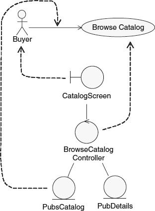
FIGURE 12.7 Use case analysis – mapping use case elements to standard abstractions
 Boundary
 classes: representing the interfaces to the outside world (either to a human actor's interfaces derived from the screens of the UX model or interfaces/APIs to actors representing external systems). Figure 12.7 shows the “CatalogScreen” as an example for a boundary analysis class.
- Controller class: representing the use case's actual flow of events, that is, the functional behaviour expressed by a set of operations mapping the use case's input/output round trips. It is a recommended practice of use case-based analysis and design to identify one main controller per use case. Figure 12.7 shows “BrowseCatalogController” as an example for a controller analysis class.
- Entity classes: representing the inputs and outputs of the use case, that is, the data flowing into the system and out of the system. Figure 12.7 depicts “PubsCatalog” and “PubDetails” as examples for entity analysis classes.
As indicated above, controllers represent use case-specific behaviour aiming to provide an overview of the system responsibilities or services that need to be realised or made available for the use case. Boundaries and especially entities are modelled with the perspective to use them in more then one use case realisations. For example, it is likely that the data abstraction “PubDetails” will also be used in the realisation for the “Checkout” and “Maintain Shopping Cart” use cases.
Use Case Analysis Dynamic View: Distribute Use Case Behaviour
Thus, after this first step of identifying these static abstractions, your second step of the analysis is walking through the use case specification round trips and distributing the use case behaviour to the classes by assigning responsibilities. Behaviour is best represented with the UML's interaction diagrams such as sequence or collaboration diagrams. As you saw in Figure 12.5 there are three round trips in the use case's basic flow: “load the catalog”, “search”, and “show details”. The procedure for distributing responsibilities for these three round trips is determined by following the stereotypes:
- Boundaries take commands and input from actors and forward them to the controller for processing.
- The controller uses entities to persist and/or retrieve data to deliver output to a boundary for display to an actor.
Figure 12.8 shows the resulting sequence diagram after distributing the three round trips for the “Browse Catalog” basic flow to the abstractions of Figure 12.7 (plus another boundary added for the publication details transforming our duck into a duck with two heads).
For example, the use case's first round trip describes how a catalog page is retrieved, labelled as a “load()” command issued by the actor through the user interface (probably by typing the URL of our sales webpage). That is delegated by the boundary “CatalogScreen” representing this page to the controller via the “getCatalog()” responsibility. That in turn retrieves the requested information from the entity “PubsCatalog”.
The result is then displayed in the same boundary from which the initial request came, via the “displayTitles()” responsibility. As you can see, all three round trips of our case study use case describe simple, technology-independent data retrieval operations, and thus all look very similar in their realisation.
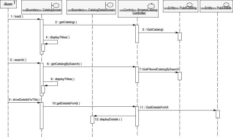
FIGURE 12.8 Allocating use case behaviour to analysis class responsibilities in sequence diagrams
Use Case Analysis Static View: Describe Relationships, Responsibilities, Attributes
The third step in use case analysis is to update your classes as depicted in Figure 12.9, with the responsibilities and relationships identified in the sequence diagram.
As a result, responsibilities are added as operations. When one class calls another class's responsibility, a relationship between the two classes is added. Between classes with different stereotypes it does not really matter at this point if you use associations (expressing a structural relationship) or dependencies (expressing local-variable or parameter-usage relationships). This will change during design anyway depending on the technology and design mechanisms used to realise these abstractions. Nevertheless, it is important to capture that these classes need to know each other to design their relationship appropriately. On the other hand, relationships between classes of the same stereotype, especially for the entity classes, represent important analysis results (as you will see in Figure 12.10). Figure 12.9 shows the extended “duck-on-skis” resulting after this step, which actually many UML design tools generate automatically or semi-automatically from the sequence or collaboration diagrams.
Looking at this diagram and comparing it against the use case text from Figure 12.4, you can see that you so far mapped the dynamics, but not all the static requirements expressed in the use case to your classes. For example, for “Step 1”, we realised the “The system displays the first page of all publications available.” part with the association between the “CatalogScreen” and the “BrowseCatalogController” and a dependency to “PubsCatalog” representing the data retrieved and presented, as well as the operations “CatalogScreen::load()”, “BrowseCatalogController::getCatalogPage()”, and “CatalogScreen::displayTitle()”.
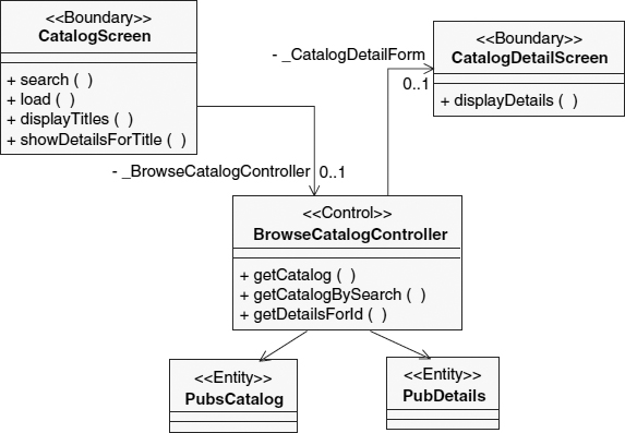
FIGURE 12.9 Analysis class diagram derived from sequence diagram in Figure 12.8
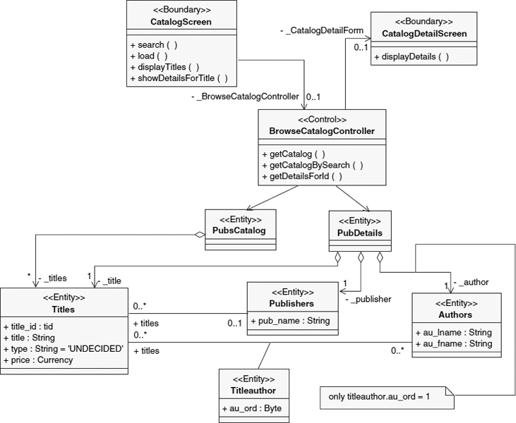
FIGURE 12.10 The completed participants class diagram after analysing “Browse Catalog”'s Basic Flow
The second sentence of “Step 1”: “It displays for each publication a unique identifier, its title, and price.” is not yet mapped into the model. First, you might want to argue if this information is actually to be found in the use case specification or not. Clearly, different use case writing styles might factor these requirements into a separate section (data requirements) or completely different supplementary specification documents; or keep this information just as part of the User Experience model6. Nevertheless, although it is not important where we get this information from, detailed data specifications are essential for analysis. Therefore, you work with these requirements in the fourth step of analysis by refining the model to include an actual structure (in terms of associations and attributes) of how publications need to be represented in the system. This is the really creative part of the analysis. Whereas before, we performed a standard mapping from the use case to classes, we now need to make decisions on how to represent the data, that is, organise our entities. You cannot make good decisions based on one flow of one use case, because you want to structure the data to fit the requirements of all use cases that make use of it. However, you need to start somewhere, and other steps of the analysis deal with the integration of different use case results. Further, during design you will make more changes to these structures to meet non-functional requirements and technology-specific constraints. Thus, Figure 12.10 shows my initial decisions applying perhaps also a bit of foresight on what else will have to be realised with these entities.
This lower part of the model in Figure 12.10 comprising of new entities will evolve, in comparison to more classical data modelling techniques, into the so-called logical data model which is the basis for data-related modelling in design. Your ultimate verification step (especially after making changes while integrating with other use case analysis results) is to walk through the use cases to verify that the classes indeed support the specified behaviour.
As a result, what you see in Figure 12.10 is the UML class diagram representing the static structures needed to support the use case “Browse Catalog”. Such a use case–specific diagram is also called the Participants diagram.
Your fifth step in the analysis is to integrate this participants diagram with the other participants' diagrams in so-called Analysis Elements diagrams. However, because we only have space to work on one use case in this chapter, refer to RUP (2003), Eeles et al. (2002) for examples on this step.
Managing and Tracing Analysis Results
As you can see from this small example, you will generate quite a few diagrams showing your analysis results from different viewpoints (such as dynamic and static). You will do this for every use case you analyse. To control complexity and to maintain traceability to your use cases, you should set up a canonical model structure for your diagrams and model elements. The UML supports this with the concepts of Package and Collaboration. Good design tools support hierarchical displays, allowing you to set up such data structures, as shown in Figure 12.11.
As you can see in Figure 12.11 the analysis model is structured into two main packages,
- Analysis elements package: Representing the integrated static structure view on our analysis results. Although Figure 12.11 only shows the results after analysis of “Browse Catalog”, this package will always contain the continuously integrated results after merging all the use cases analysis results currently available. This ensures that analysis of the next use case will reuse and update the existing classes, and avoid reinventing abstractions already present.
- Analysis use case realisations package: Representing a view of each use case including the use case-specific static participants diagrams as well as dynamic interaction diagrams. These diagrams refer to model elements maintained in the Analysis Elements package, which has the advantage that when classes are updated based on the analysis of other use cases, the updates are reflected in classes participating in the use cases already analysed. The results of every use case analysis are organised as part of a use case realisation that has the same name as the use case for traceability reasons. As you can see in Figure 12.11, the “Browse Catalog” use case realisation (modelled as an UML collaboration instance) consists of its participant diagrams (shown in Figures 12.9 and 12.10) as well as an Interaction Instance for the use case's basic flow, and a sequence diagram as well as the objects being presented in the sequence diagram.
FIGURE 12.11 Analysis model structure
It is important that a project-wide model structure guideline exists, to provide a well-defined way of organising the ‘electronic filing cabinet’ of UML diagrams. I have seen many projects where the lack of such a uniform guideline has not only led to the loss of traceability, but also to the loss of analysis or design results, because they were hidden somewhere deep down in an undocumented package hierarchy.
Object-Oriented Design with Use Cases
Let's move on a step further in software development, and discuss how to design our use case “Browse Catalog” based on the analysis results presented in the last section. The objective is to map the analysis results to a concrete technology-specific realisation, covering both functional and non-functional requirements, and design constraints. To save space, I will only describe the mapping of the functional requirements into technology. I have chosen to use the .NET framework, with ASP .NET as the solution technology for our sales web application.
Software Architecture and Use Cases
To cover the mapping of non-functional requirements and to truly understand the decision-making activities conducted during software design, we would have to define Software Architecture first.
Software Architecture encompasses the set of significant decisions about the organisation of a software system.
Unfortunately, architecture is beyond the scope of this chapter. Again, see RUP (2003), Eeles et al. (2002), Conallen (2002).
However, because architecture is seen as a non-trivial task, one can find many OOAD stakeholders offering ways of reusing architecture in specific domains and technologies. These reuse strategies are normally described as architectural frameworks and design patterns. They are often delivered by technology providers to help make their technologies successful7. See for example the J2EE technology in Alur et al. (2003); .NET technology at Microsoft (2003), Fowler (2002) covering both.
Typical enterprise application architectures are very often organised in layers of concern, for example, separating presentation from business logic from data storage and access. The question of interest in this section is: How do we map use cases into such a solution structure? In Figure 12.12 we see that all parts of the use case can have an influence on all parts of the architecture. This also means that a change in a use case (e.g. a new field to be shown in the details screen) will trigger changes in all these levels in all possible packages. Therefore, we need to find a way to organise our Design Use Case Realisations to keep trace of what part exactly is being designed for what use case requirement. Of course, we are going to do this via the Analysis Use Case Realisations: Tracing to the use case from the analysis model from the design model.
Use Case Design Overview
In use case design, we systematically transform and refine the analysis classes captured in our analysis use case realisation to technology-specific design classes. Looking at our analysis model results of Figure 12.10 and the layers of Figure 12.12 you might think the mapping is obvious: let's put the boundaries into the presentation tier, controller into the business layer, and entities in the data access layer. Unfortunately, it is not that straightforward. As with the use cases, can all parts of the analysis model have an influence on all parts of the architecture? Consider for example entities: They have an influence on the design of all layers and the interactions between them. Publication catalog data (Entity “PubCatalog”) is needed in the presentation tier, because it has to be displayed on the screens. It is processed in the business layer (e.g. if you would extend your use case to calculate rebates on the prices for a particular category of customers). It is accessed in the database and defines the structure of the database schema (not represented in Figure 12.12). Also, to be able to send the data from the database over the internet to the COM+ MTS application server executing the business logic and from there to the IIS web server using .NET Remoting, another representation of the “PubsCatalog” entity is needed to support this.
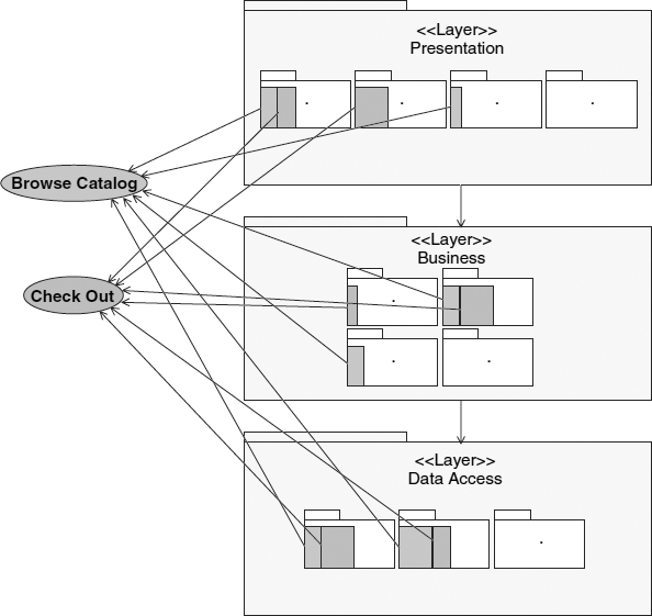
FIGURE 12.12 Relationship of use cases to layered architecture
To clarify this point I already present in Figure 12.13 some final design results. This traceability diagram shows how your analysis classes have been mapped to respective design classes. Here you see the mapping of “PubsCatalog” to database tables, an ASP .NET Server Page (containing controls to present the data; not shown), as well as a class Common::PubsCatalog that represents an ADO .NET dataset for transfer between servers utilising XML. The “BrowseCatalogController” also has been split into three classes covering two different concerns: presentation specific logic and business specific logic. The “BrowseCatalogWebContoller” represents the logic realising the navigation flow in the web application, for example, which screen to use for which presentation in which particular order, which business component to contact to get business logic processed, and so on. A windows forms user interface would do things quite different. Thus, you would like to separate presentation from business logic to increase reusability of the business part. This type of presentation logic is also completely different for an application interface providing web services, which also has been model in Figure 12.13 with the “PubWS” class. Web services are intended not to provide a user interface, but an application interface for catalog functionality over an HTTP protocol8. The other concern of representing the pure business logic for browsing the catalog independent of the presentation form is realised with the “PublicationsManager” component that we design in the next section. Finally, if you remember that boundaries do not only represent UI responsibilities, but are also used to model APIs to access external systems (not the case for “Browse Catalog”), you can also see that these sometimes need to be mapped to design on different levels of the architecture than the presentation tier.
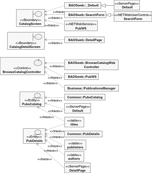
FIGURE 12.13 Mapping of analysis to design classes
To design a use case realisation, you start by identifying design elements as we just discussed and presented in Figure 12.13 and then continue to systematically transform analysis elements of your analysis use case realisation with these design elements. You will do this now for “Browse Catalog” bottom-up, that is, specify and refine a design element representing a business component9 in the next section and then in the following section replace elements of our analysis model with this component and other design elements. Surely, this could also be done the other way round: top-down. This is merely a matter of preference (as well as availability of already designed model elements) and normally performed in a more intertwined way.
Component Design
Components represent the realisation of sub-systems for software applying the principles of encapsulation to minimise dependencies between different parts of the application to achieve more resilience; for example in respect to change impact. Therefore, software components constitute black boxes providing realisations for functions and non-functions. As for all systems, we produce specification and realisation documentation for components. Hence, we could actually draw a use case diagram for our component “PublicationsManager” and describe in a use case specification round trips of an actor (in this case a class from the ASP .NET user interface) calling the component. A more popular, but less goal-oriented way as use cases, for representing component specifications, is depicted in Figure 12.14.
Figure 12.14 presents the black box specification of our component defining its interface “IPublicationsManager”, which as for every system interface describes input-output transformations, is this case using UML operation declarations. The “PublicationsManager” sub-system is represented as a package realising the interface that contains the white box model elements doing the actual work of providing catalog data in a paged and searchable manner. These elements are developed with analysis and design activities in a very similar way as we discussed throughout this and the last section for the overall “Browse Catalog” use case and omitted for space reasons. See (Cheesman and Daniels 2001) for an excellent discussion on software components, their specification, and realisation with UML.
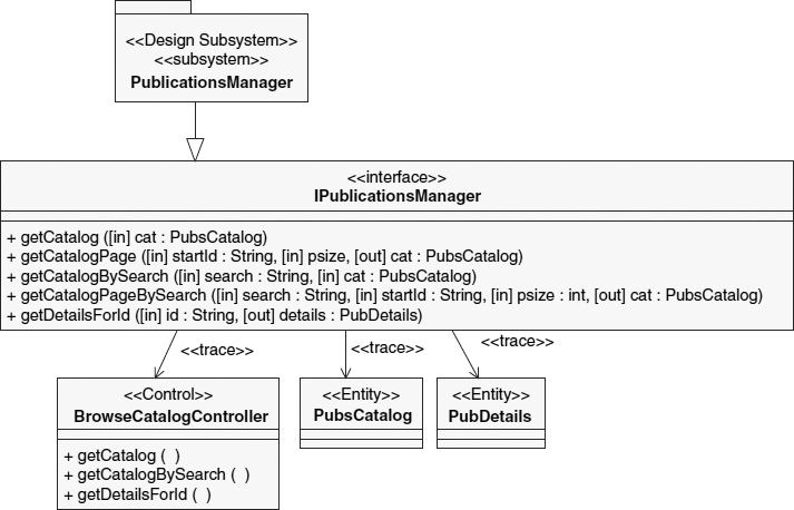
FIGURE 12.14 A component specification
UI Design and Completing the Design Use Case Realisation
In this final section, you will now put a user interface on top of the “PublicationsManager” component. We do this by taking the analysis model elements and transforming them to the design elements of Figure 12.13 resulting in updated interaction and participants diagrams. The way the design elements in Figure 12.13 had been actually identified was by applying several design patterns from (Microsoft 2003) [“Model-View-Controller with ASP .NET” and “Data Transfer Object”] and (Fowler 2002) [“Application Controller”]. An architect's responsibility is to select the appropriate set of patterns to be used for use case design in a repeatable and predictable fashion and documenting them as so-called Design Mechanisms (RUP 2003). Using the same mechanisms for similar design tasks in every use case ensures maintainability of the design as well as centralises architectural decision-making ensuring that not every designer invents his own solutions.
Figure 12.15 depicts the updated sequence diagram after incorporating the design elements and patterns. Our actor Buyer interacts with classes representing ASP .NET code-behind pages classes10, which in turn interact with the “BrowseCatalogWebController” class. The web controller class uses the “PublicationsManager” to interface with the business component discussed in the last section.
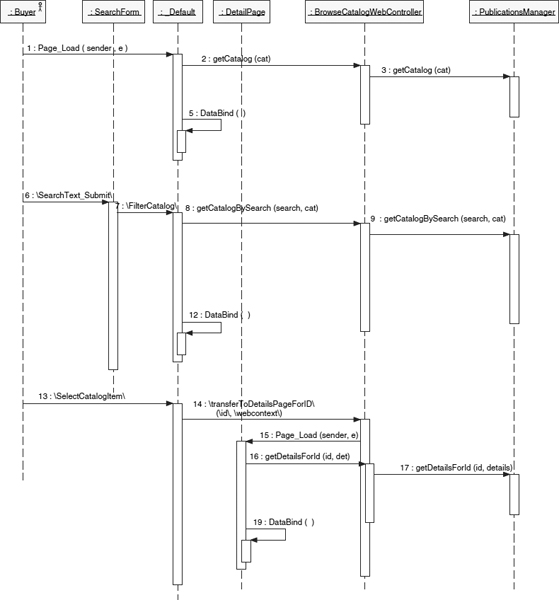
FIGURE 12.15 Design use case realisation – sequence diagram
Figure 12.16 shows the updated participants diagram. It presents the classes from Figure 12.13 as well as resulting relationships from the sequence diagram. For example, we see that relationships had to be added in our design such as associations of the ASP .NET pages' code-behind classes to the dataset classes “PubsCatalog” and “PubsDetails”. These classes contain the data the “PublicationsManager” component retrieved from the database that has to be displayed in our pages and therefore have to be accessible in the code-behind classes for presentation generation and event-handling operations.
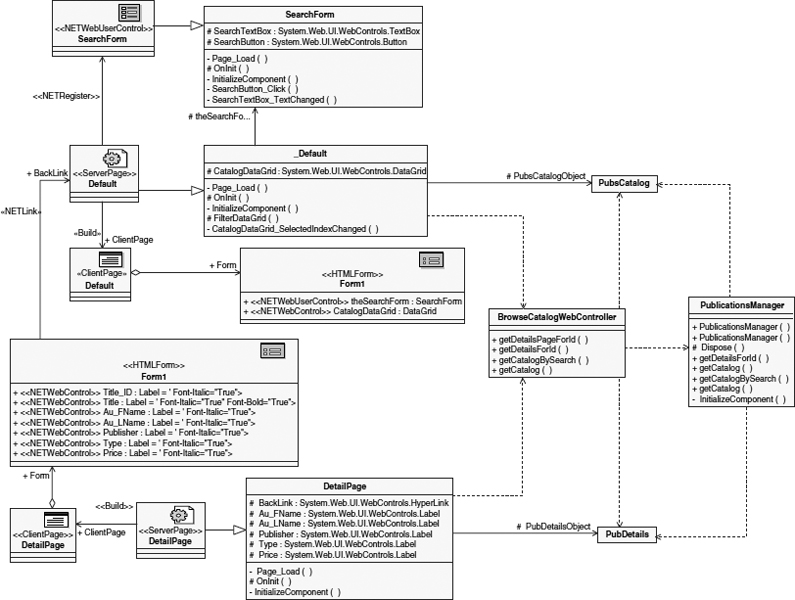
FIGURE 12.16 Design use case realisation – participants diagram
To cut this technical discussion short, we see in these two diagrams that the essential analysis model has been transformed and extended for the concrete technical platform they are supporting. It is now imperative to verify that the “Browse Catalog” use case is still fully supported as specified after all these changes by reviewing sequence and class diagrams against the use case specification with a walkthrough. Finally, the implementation derived from this design will be tested against scenarios of the use case as well.
SUMMARY AND COMPARISONS
This concludes this chapter in which I walked you through analysis and design with use cases. My intention was to provide system analysts with a basic understanding of what designers actually do with their use case artefacts to improve their ability to include them as an intended audience for their use case writing.
In contrast to many of the scenario and storytelling techniques presented in other chapters of this book, use cases represent a compromise between formality and natural language expressiveness. Kent Beck's use of stories in Extreme Programming (Beck 2000, and see Chapter 13 of this volume) is a more informal and more ‘agile’ approach. This compromise is between facilitating interdisciplinary communication on the one hand, and providing enough structure to drive software development activities (such as user-experience modelling, analysis, and design) systematically on the other.
In addition, unlike scenarios and stories, use cases focus on actor values and are therefore not decomposed into smaller parts that would not have that focus, and which would be hard to understand, to see the rationale for, to verify, and to validate. Consequently, analysts—not users or customers themselves—need to write the use cases, but users must still be able to relate to them and perhaps claim intellectual ownership of them. To encourage such an understanding within the interdisciplinary development team, a use case writing style guide should be established formalising the way use cases steps are written, flows are structured, glossary terms are referenced, and so on.
Several of the elicitation techniques described in other chapters of this book can and should be applied to get to the actual use cases and to improve them. For example, Ellen Gottesdiener's use case workshops (Chapter 5), Karen Holtzblatt's contextual inquiry (Chapter 10), and Neil Maiden's scenario walkthroughs (Chapter 9) are all valuable techniques.
KEYWORDS
Use Cases
Requirements
Object-Orientation
Analysis
Design
UML
Model-Driven Development
Rational Unified Process
REFERENCES
Alur, D., Crupi, J., and Malks, D., Core J2EE Patterns, 2nd ed., Sun Microsystems Press, Prentice Hall, 2003.
Beck, K., Extreme Programming Explained, Addison-Wesley, 2000.
Beyer, H. and Holtzblatt, K., Contextual Design. Defining Customer-Centered Systems, Morgar Kaufmann Publishers, 1997.
Bittner, K. and Spence, I., Use Case Modeling Addison-Wesley, 2003.
Cantor, M., Rational Unified Process for Systems Engineering, The Rational Edge, August-October 2003, www.therationaledge.com
Cheesman, J. and Daniels, J., UML Components: A Simple Process for Specifying Component-Based Software, Addison-Wesley Longman, 2001.
Conallen, J., Building Web Applications with UML, 2nd ed., Addison-Wesley, 2002.
Eeles, P., Houston, K., and Kozaczynski, W., Building J2EE Applications with the Rational Unified Process, Addison-Wesley, 2002.
Fowler, M., Patterns of Enterprise Application Architecture, Addison-Wesley, 2002.
Heumann, J., Generating Test Cases From Use Cases, The Rational Edge, June 2001, www.therationaledge.com
Jacobson, I., Use Cases—Yesterday, Today, and Tomorrow, The Rational Edge, March 2003a, www.therationaledge.com
Jacobson, I., Use cases and aspects—working seamlessly together, Journal of Object Technology, 2(2), 7–28, 2003b, http://www.jot.fm/issues/issue_2003_07/columnl
Jacobson, I., Booch, G., and Rumbaugh, J., The Unified Software Development Process, Addison-Wesley Longman, 1998.
Kruchten, P., The Rational Unified Process: An Introduction, Addison-Wesley, 2000
Kroll, P. and Kruchten, P., The Rational Unified Process Made Easy: A Practitioner's Guide to Rational Unified Process, Addison-Wesley, 2003.
Microsoft, Enterprise Solution Patterns Using Microsoft.NET, 2003, http://msdn.microsoft.com/practices/type/Patterns/Enterprise/
OMG and IBM Rational, Unified Modeling Language Specification, Version 1.5, 2003, http://www.rational.com/uml
Royce, W., Software Project Management: A Unified Framework, Addison-Wesley Longman, 1998.
RUP 2003.06, Rational Unified Process, IBM Rational Software, 2003.
RUP SE v2.0 2003.06, Rational Unified Process for Systems Engineering Plug-In, Rational Developer Network (www.rational.net), IBM Rational Software, 2003.
Yu, E., Towards modelling and reasoning support for early-phase requirements engineering, Proceedings of the 3rd IEEE International Symposium on Requirements Engineering (RE '97), Washington, DC, January 6–8, 1997, pp. 226–235
RECOMMENDED READING
(Self-Reference) The diagrams in this chapter were created with IBM Rational XDE Developer for Visual Studio .NET 2003.06. These models and the executable code in C# as well as VB .NET code for this example can be downloaded from http://haumer.net/rational/BAOS/
(Bittner and Spence 2003) A comprehensive coverage of use case techniques and practices for requirements management, including useful examples showing how use case specifications evolve over time.
(Eeles et al. 2002) An example-based introduction to RUP and in particular OOAD for designing J2EE applications.
(Conallen 2002) An excellent introduction to the basics of web application development in the context of the RUP. This book also shows how to use the UML and RUP's OOAD workflow to model web applications, introduces the Web Application Extension to the UML used in the design diagrams of this chapter, as well as user experience modelling.
(Jacobson 2003) describes how use cases naturally support Aspect-Oriented Programming (AOP). He explains how use cases represent the “crosscutting concerns” of aspect-orientation, because they will be realised throughout the solution. Thus, a use case realisation represents one “aspect” of the architecture, that is, a modular unit of crosscutting implementation. Download this paper to learn how the things you learned here fit with this new trend in software engineering.
1 An individual who is affected by the outcome of the project.
2 When Authentication exactly happens in the flow of events is not expressed in the diagram, but the textual use case specification. However, using the includes-dependency in the diagram sensitises the audience for this fact and is used for communication about it.
3 This UML representation of a goal as a stereotyped class with the target icon as well as respective relationship stereotypes has been recently introduced in (RUP 2003).
4 Which is in most cases dependent on the technology you apply: For example, you tweak performance by choosing for specific component types and configuration settings for your middle tier server, or reliability with replication and redundancy features supported by certain server technologies, usability by applying certain styles and UI paradigms of a specific UI technology (standardised design principles and guidelines for Windows forms are quite different than for web forms), and so on
5 For example, see the UML specification 1.5 (OMG and IBM Rational 2003) which defines these stereotypes in the example UML profile for software development.
6 Another style I discovered in the field with more classical Structured Analysis educated system analysts is to only capture data requirements in the analysis model itself. However, my experience shows that it is advantageous to capture data in the requirements specification or at least the user experience model, because these representations are much easier to understand for stakeholders who have to review, validate, and decide on these requirements.
7 Successful in respect to concerns such as resilience of the application, cost of change and extensions, facilitation of reuse, realisation of a large set of standard non-functional requirements, and many, many more.
8 You see two classes called PubWS, one representing the web service controller (would be realised with a .NET asmx.cs file), the other the application interface mapped to the boundary (would be realised with an .asmx file).
9 To save space, we start in the middle layer and omit the data access layer.
10 ASP .NET defines for a server page two classes: one class for the HTML presentation content as well as a second class, called code-behind class the first one derives from through specialisation, for event-handling and dynamic presentation generation.