
CHAPTER 15
PROJECT STORIES: COMBINING LIFE-CYCLE PROCESS MODELS
Andrew Farncombe
John Boardman Associates Limited, Southampton, UK
THIS CHAPTER applies scenario thinking to the system development process itself. Projects succeed when their requirements are right and development is effectively managed to control risk. Both of these aspects often lead to iterative development life cycles (e.g. requirements are often gathered iteratively in a series of scenario workshops). The simplest life-cycle story is the single-pass ‘waterfall’; in this chapter, the shortcomings of that story are examined, and an approach is developed that shows how to combine three kinds of life cycle to suit a wide range of project situations.
APPLICABILITY
The ‘systems of interest’ dealt with in this chapter should be not be thought of as implying any particular implementation technology. Systems comprising mechanical, electrical, electronic, software, and other solutions are all within the scope of the discussion. This requires a more general approach than, say, software development methods designed to be used within familiar implementation domains, possibly employing regularly occurring requirements and design ‘patterns’.
Scenario use is almost by definition participative, and several authors in this volume explicitly involve stakeholders: for example, Suzanne Robertson in Chapter 3, Ellen Gottesdiener in Chapter 5, Karen Holtzblatt in Chapter 10. Stakeholder participation implies a willingness to listen to and accept changes as understanding develops. Hence, iteration is more or less mandatory. The applicability of the concepts in this chapter is not restricted to scenario-based development, but—along with the management of risk—the use of participative techniques such as scenarios makes the choice of more sophisticated life cycles essential.
POSITION IN THE LIFE CYCLE
Almost by definition, the ideas explored in this chapter relate to all the life-cycle elements shown in the table below. This is because we will be reasoning about the construction and applicability of life-cycle processes in the most general sense. However, in what follows, we question explicitly whether the ‘waterfall’ life cycle depicted below (Royce 1970) is a sufficiently rich model to handle the wide range of project situations we typically encounter. Concluding that it is not, we use an enquiry-based approach to generate life-cycle models suitable for projects in different situations.
![]()
KEY FEATURES
- The project life cycle is itself treated as a story.
- Composes project-specific life cycles from three basic life-cycle models.
- Adapts traditional thinking to suit risky projects, such as those with vague requirements and multiple stakeholders.
STRENGTHS
- Accommodates a very wide range of project scenarios.
- Not confined to computer-based or software systems.
- Can compose three basic life-cycle models to generate other life cycles.
- Offers a general enquiry-based framework for thinking about system development processes.
- Clearly distinguishes in-the-large iteration from in-the-small life-cycle sequence of activities.
WEAKNESSES
The ideas contained in this chapter challenge some basic assumptions, for example, that there is one perfect process model. Not everyone is receptive to this way of thinking and ‘shooting the messenger’ is a phrase that springs to mind when I think of my experiences trying to apply it. My advice therefore is that if you find the ideas expressed here attractive and/or useful, take care how you sell and use them.
TECHNIQUE
Introduction
This chapter may feel rather different from the others in this book.
Usually, we use scenario modelling or storytelling as a way of structuring what we know about some user domain. We do this to help us construct a system that will operate inside that domain and interact with the surrounding environment as required, providing some cost-effective benefit to the stakeholders in doing so.
By contrast, the ideas presented in this chapter apply storytelling not to constructing the system itself, but rather to the systems engineering processes used to direct the analysis and development activities involved. The story elements that we are concerned with are descriptions of parts of the development process; the resulting stories are composed for each project's situation according to a set of quite general rules.
Why do this?
From my experience, it seems that there is a lot of bad systems engineering process thinking ‘out there’, variously muddle-headed or inappropriate.
Bad process thinking can be worse than having no process at all. People lose the plot: ‘Tell me again what I'm supposed to be doing’. Paralysis sets in: ‘Why am I doing what I'm doing? Where does it get me?’. People feel cut off from common sense and what experience has taught them.
To be fair, people who write systems engineering processes have their hearts in the right place. They are attempting to encapsulate relevant wisdom and experience, and so lessen the chances that each project will have to learn project facts of life the hard way.
The trouble is that standardised process templates often suffer from the ‘one size fits all’ malaise. The institutionalised process model often does not fit individual projects. Projects have different shapes due to individual project circumstances and institutionalised process models fail to capture this variability.
To take a sideswipe at the life-cycle model used in the introduction to this chapter: to what extent is it realistic? Here it is again:
![]()
To be sure, each of the stages in the ‘waterfall’ is necessary. Omit any one of them, and you have a distinctly dysfunctional project. Broadly, the sequencing is correct. It would be absurd to code the system before you have discovered what the requirements are (although there have been plenty of projects in which people have tried to do precisely that!). Furthermore, the approach, as introduced by Royce (1970) (who appreciated that iteration was necessary), and defined in popular standards such as Mazza et al. (1994), was certainly an improvement on unstructured development.
But let us constructively criticise it:
- There is a distinctly left to right, single-pass, do-it-all-in-one-go, ‘big bang’ feel about it. How do notions such as ‘concept exploration’, ‘proof of concept’, and ‘phases’ fit in?
- There seem to be firm walls between each stage stating which mode your brain is supposed to be in at any one time. Experience tells us that in practice, the engineer's mind jumps about from thinking about requirements, to thinking about solutions and how they might be implemented, and back again. This is not reflected in the model.
- There is the strong implication that we are starting with a clean sheet of paper (the ‘green field’ situation). What about ‘brown field’ situations in which we have to add some functionality to an existing system, or modify it in some way while it continues in service? How could it apply to the use of Commercial Off-The-Shelf (COTS) components and software?
- Iteration is not reflected at all. There is no sense of building prototypes and trying them out, feeding lessons learned back into the development process.
- Phasing of deliverables and incremental build-up of functionality and/or deployment is not represented. System upgrades and improvements are not dealt with.
So, although the story told by the model is in some senses correct, it also omits many project aspects that we all know to be a necessary part of project life. In fact, it is rather simplistic and inflexible. As a result, it may not be appropriate for many practical project situations.
Yet many organisations mandate exactly this sort of life cycle in their project standards, with high-level Gate or Phase Reviews punctuating the life-cycle stages.
If a project's life cycle itself fails to reflect the realities of the project's situation, a disconnect develops between organisational process mechanisms and the realities of the project. Management reviews can become meaningless.
Cultural factors within the organisation often inhibit resolution of this problem. From Management's point of view: developers and engineers need to be controlled and do what they are told. Many developers, on the other hand, feel that the process constrains creative and intellectual freedom and is imposed without consultation. In a business world characterised by ‘initiative fatigue’, an imposed process model is just another management fad du jour, and as a result, many of the people involved just go through the motions. In this situation, the benefits of all the cumulative experience of systems engineering fail to accrue and projects start out at a disadvantage.
This chapter is a plea from the heart against process rigidity. It looks at what can be done to provide useful process models that on the one hand support constructive systems engineering, while being flexible enough to reflect the needs of projects on the other.
However, it is one thing to criticise processes as being inflexible and simplistic. It is quite another to do something about it. On the basis, therefore, that to understand is to forgive, we look at why things are as they are.
It seems to be quite difficult to define effective systems engineering processes. Why is this? Several important factors seem to be at work:
- Muddled ‘process levelling’ (explained below).
- Insufficient attention paid to ‘project characterisation’ at the outset of a project.
- The concept of ‘meta process’ does not seem to have occurred to most people.
- Silly and false demarcations between management and technical issues when it comes to process definition.
Muddled Process Levelling
In any systems engineering process, there need to be two equally important levels working in concert, which we here refer to as SE ‘in the large’ and SE ‘in the small’. However, the following situations are commonly encountered:
- Failing to recognise that these two levels even exist
- Muddling the two levels up
- Having insufficient variety or richness at either level Resultant problems include
- Inappropriate programme ‘shapes’ that lead to process rigidity as described above
- Inability to reduce risk systematically
- Inability to accommodate iteration
I should confess at the outset that I have had some difficulty in choosing names for these levels since there are many candidates available. There is also a danger of choosing a name that is overloaded by other concepts taken from closely related disciplines. This seems to be because of the great disparity between the number of concepts we have to give a name to in the modern world and the number of names available. So, let's make an accommodation: you as reader retain the right to disagree with my choice of name and suggest a better one.
The first level is about systems engineering ‘in the large’. It is at this level that we find words like ‘phase’, ‘concept exploration’, ‘proof of concept’, ‘feasibility study’, ‘project definition’ ‘full development’, ‘in-service maintenance’, ‘in-service upgrade’, ‘disposal’ and so on. It can also be thought of as the macro picture of an entire project from cradle to grave, comprising a number of subprojects that make up the whole life cycle. It is at this level that risk can be managed most effectively. Budgets can be assessed on the best information available at the time and allocated in digestible portions. Sensible high-level review points can be inserted at which management takes stock of whether the overall project is proceeding as required and whether money is being well spent.
Other possible names for this level might be ‘macro’ systems engineering, as opposed to ‘micro’ systems engineering (see below). Actually, this is quite a good name. Unfortunately (and with no disrespect intended), Booch (1994) uses the term in the context of Object Orientated development with a somewhat different meaning. One could of course borrow the term and assign it the meaning described in this chapter, but that might cause confusion.
Another term might be ‘Life-Cycle Level’. This suffers from the problem that it is too general; it is overused and overloaded with different meanings. For instance, the sequence of steps or activities that we started this chapter by discussing is itself referred to as a life cycle. As the reader will soon appreciate, it is precisely the need to distinguish between these activities and project phases ‘in the large’ that we are trying to emphasise. If we choose ‘Life-Cycle Level’ to mean ‘in the large’, there seems little to prevent people from saying ‘Oh yes—I know what you mean. You mean the following sequence of steps:’
![]()
Oh no we don't! We want to distinguish this sequence of steps from those ‘in the large’ and give a special label to them.
This brings us neatly to the point at which we introduce the second level of the systems engineering process. In fact, we have given the game away. The second level is broadly the sequence of activities shown in the table above.
We call this systems engineering ‘in the small’. It concerns sequences of activities such as: user requirements, system requirements, architecture, system design, subsystem identification and specification, preliminary design, detailed design, implementation, test and integration, acceptance tests, certification, training, commissioning, and handover.
Why have we made this separation between ‘in the large’ and ‘in the small’? Simply because ‘in the small’ is necessary but not sufficient for general systems development and project management. ‘In the large’ is needed to handle the sufficiency issue—that is, the bits that the ‘in the small’ process does not address.
At this stage, we should stress that we are not using the terms ‘large’ and ‘small’ in a pejorative sense. ‘Large’ does not mean more important than ‘small’. To labour points already made:
- For any practical systems engineering/project management process model, you need to reflect and accommodate both levels explicitly.
- Focusing on one level at the expense of the other is a mistake, although both errors are encountered in practice.
- One often sees just one level depicted, with the other implicitly struggling to get out.
- There are a number of different ‘in the large’ models in use. Often one hears the claim that one particular model is the right one to use. Some people become almost religiously zealous when it comes to this. But this is inappropriate; there is no one correct ‘in the large’ model. To insist that this is the case is to invite and encourage process rigidity. ‘Horses for courses’ thinking should prevail. Choose the one that seems most appropriate for the project in question. This last point of course has an effect on people who write process standards. If there is process diversity in the large, what do you put in your process standard?
The answer seems to be that your process standard should instead be a meta process, or a process for generating a process. This seems to be a particularly powerful concept, since it seems to offer at a stroke full generality, flexibility and recycling of systems engineering good practice. It also requires you to have risk assessed the project and asked pertinent questions about how the project is likely to unfold (and having to do these cannot be considered a bad thing!). The ideas underlying meta processes are discussed in detail below.
Systems Engineering ‘in the small’
We have already introduced and motivated systems engineering ‘in the small’ in the previous section. Most readers will recognise the activities, but for consistency and completeness we have tidied up the terminology used because reference is made to them extensively in the section on systems engineering ‘in the large’. This is also the reason why we start our discussion ‘in the small’.
Here are the ‘in the small’ activities
- User Requirements Definition (URD)
- System Requirements Definition (SRD)
- System Design/Architecture (SD/A)
- Preliminary Design (PD)
- Detailed Design (DD)
- Implementation (Imp)
- Test and Integration (T&I)
- Acceptance and Certification (A&C)
Note that we have consciously differentiated User Requirements from System Requirements as in Mazza et al. (1994). This is viewed as a contentious issue by some: they maintain that the distinction between User and System requirements is spurious and that in reality there are just ‘requirements’. To be fair to this way of thinking, it is certainly true that requirements can at times be difficult to pigeonhole within this classification scheme. However, it seems equally obvious that there are two ends of a spectrum involved here, and that labelling the extreme points is a useful way of ensuring that a balanced requirements specification is produced.
User Requirements Definition (URD)
This activity is centred on the world of the User. ‘User’ is itself a troublesome word. Who is ‘the user’? Very rarely is it just one person. Usually, the ‘user’ is a collection of stakeholders (i.e. identifiable individuals), some fulfilling more than one role. The essence of being a User is that the system is being built/procured for them. Without them, there would be no point in acquiring the system.
The stakeholder roles (see also the section on Stakeholders in Chapter 1, Introduction, of this volume) can be categorised, for example:
- Beneficiaries
- Functional (i.e. whose jobs will the system make easier or more effective?)
- Financial (i.e. which stakeholders will the system make richer?)
- Operational
- Who is going to operate this system?
- Which other systems have to interoperate with this system?
- Negative
- Who has to be appeased/placated when building and operating this system?
This process of finding out the composition of the user community is often called ‘stakeholder identification and analysis’ and can be viewed as a subject in its own right.
The process of finding out what these stakeholders do and what their needs are is similarly a specialised topic. Indeed, it can be argued that this is what the rest of this book is about! Suzanne Robertson's approach to Requirements Discovery (Chapter 3) is a good example.
There are also categories of nonfunctional user requirements, such as:
- Cost
- Timescale
- Reliability
- Maintainability
- Availability
- Usability
- Safety
- Security
- Upgradability
- and so on… (the so-called ‘ilities’, or product qualities).
System Requirements Definition (SRD)
System Requirements, by contrast, have very little (if any) connection with the motivation for the system. Instead, they can be viewed as the constraints that have to be applied to the system acquisition process to obtain a fit-for-purpose result. Usually, system requirements are technical in nature and cover the following kinds of specialist areas:
- Detailed Functional Behaviour (including timing/performance)
- Legislation, Regulations and Standards
- Technical Interfaces
- Environmental
- Physical
System requirements are often the things that make system acquisition difficult. This is equivalent to saying that building the system would be straightforward if it were not for having to meet all the system requirements!
Peter Haumer's account in Chapter 12 of Use Case-Based Software Development and Alistair Mavin's description of Scenarios in Rail Rolling Stock in Chapter 20 give good examples of work in this phase.
System Design/Architecture (SD/A)
I hope it is obvious from the above discussion on requirements that both user and system requirements are needed for a successful system acquisition. Focusing on one to the detriment of the other will lead to disaster. Ignoring user requirements results in a system that fails to deliver benefit; ignoring system requirements will lead to inadequate definition of functionality or a mismatch with the intended environment.
Once requirements are understood, work can begin on designing a compliant solution. We call this process ‘System Design/Architecture’. Many people use the terms ‘Design’ and ‘Architecture’ interchangeably. For this reason, we have incorporated both terms.
It is at this stage that the overall shape of a compliant solution is worked out. Principal subsystems are identified and their individual requirements flowed down and refined (sometimes called ‘derived’ requirements).
Often the SD/A will be multi-disciplinary and will have to embrace the engineering technologies applicable to the solution; for example, electronics, electrical, communications, mechanical, software, civil, and so on.
Preliminary Design (PD)
This activity is predominantly conducted at subsystem level. Its objective is to carry out sufficient design to provide confidence that the flowed-down system requirements are achievable at subsystem level. It is during this activity that a subsystem design authority commits to the flowed-down requirements. At system level, the system design authority needs to respond to the inevitable clarification requests and issues raised by the subsystem design authorities. It often concludes with a Preliminary Design Review (PDR).
Detailed Design (DD)
This activity is again conducted at subsystem level. Its purpose is to carry out sufficient design to support implementation. It should provide confidence that subsystem flowed-down requirements will be met. This activity should conclude with a Critical Design Review (CDR). This is an extremely important review. After this point, the spend rate incurs a step change increase as materials and labour are consumed. If there are any outstanding system uncertainties, it is better to sort them out at this point rather than leave it till later!
Implementation (Imp)
Here the subsystem designs are implemented using the relevant technologies, and tested at subsystem level. Testing should demonstrate that flowed-down requirements have been met.
Test and Integration (T&I)
During this activity, the individual components come together for testing as an integrated whole. Compliance with the user and system requirements should be demonstrated. If the requirements have been well-structured (e.g. by using scenarios and use cases), this activity is made a lot easier.
Ian Alexander's description of how to derive test cases from use cases in Chapter 14 illustrates some of the considerations necessary in this activity.
Acceptance and Certification (A&C)
This activity is when the user community or their representatives take a tested and integrated system and confirm that what has been built is indeed what was wanted. In highly regulated and/or high-integrity applications, this will involve approval by the appropriate certifying bodies.
Systems Engineering ‘in the large’
As mentioned above, there are a number of representative process models operating ‘in the large’. We now describe a selection of these in turn.
The point made above: that none of the following models have absolute superiority over the others, should be stressed. Rather, in a particular set of project circumstances, one model will be more relevant and therefore more appropriate.
Here is a list of some commonly encountered ‘in the large’ process models:
- Evolutionary model
- Incremental model
- US DoD model
- UK Ministry of Defence CADMID model
- RUP (Rational Unified Process)—(RUP 2003), and see Chapter 12 in this volume
- ‘Agile Methods’ (e.g. Extreme Programming (XP)—see Chapter 13 in this volume)
The basic process models are discussed in general terms in (Stevens et al. 1998, Conger 1994, Sommerville 2001).
It seems, however, that all of these can be built from a small number (three) of basic process models. Furthermore, variants and hybrids not found in the above list but which are encountered in practical situations can be constructed by composition of the three basic models.
In the above list, the evolutionary and incremental models are deemed to be in the basic set. To this we add another, which we have here called the ‘High-Risk’ model.
We will now discuss each of the three basic models in turn:
- Evolutionary model
- Incremental model
- High-Risk model
We will then proceed to examine their relationship to the commonly encountered process models listed above and ways in which they can be combined to form variants.
Evolutionary Model
Figure 15.1 shows this to be a particularly simple model—see Stevens et al. (1998). In essence, it consists of a sequence of successive versions of a product evolving over time, with feedback from version (n) into version (n + 1). Inside each version cycle, we see the ‘in the small’ systems engineering activities embedded (note that for the sake of diagrammatic brevity, production, installation, in-service support, and disposal are not shown).
What scenario would suggest the evolutionary model? It would probably include:
- A rapid rate of technological evolution.
- A tacit acceptance from customers to accept the functionality that technology can offer in the short term, rather than waiting for perfection (whatever that means). It is probably sufficient for the offering to be competitive.
- The business need is to get the product to market in the shortest time possible.
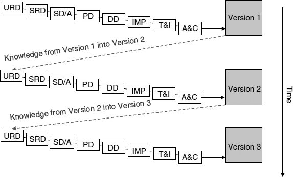
FIGURE 15.1 Evolutionary model
Markets using the evolutionary model include mass consumer products such as cars, personal computers, and PC software (i.e. operating systems and application packages).
Incremental Model
Figure 15.2 is subtly different from the evolutionary model—see (Stevens et al. 1998). In the incremental model, the system is specified and designed in broad architectural terms up front, and (in principle) the design stays unchanged thereafter. After the system specification and overall design are completed, an initial piece of functionality called Increment 1 is delivered. Some time later, some more functionality called Increment 2 is delivered, which fits together with Increment 1. Still later, Increment 3 is added, fitting together with Increments 1 and 2. And so on. (Note that as in the evolutionary model, production, installation, in-service support, and disposal are not shown. Note also that the inevitable change requests and associated configuration management activities are not shown explicitly.)
The ‘in the small’ systems engineering activities are embedded in the incremental deliveries, but notice the difference between this and the embedding used in the evolutionary model. In Figure 15.1 the complete cycle of activities is repeated for each version, whereas in Figure 15.2 the URD, SRD, and SD/A activities are factored out of the sequence of incremental deliveries and occur only once, at the outset of the project.
This distinction is important. It means that the sum of all increments represents the totality of a single system, which must be analysed and designed once at the start of the project. Thereafter, the physical increments are individually designed, tested, and delivered at successive points in time.

FIGURE 15.2 Incremental model
This aspect of requirements analysis and design once at the start of the project is not present in the evolutionary model in which the coupling between successive versions is much looser. Indeed, in the evolutionary model, compatibility between successive versions, although desirable, is by no means assured. In the incremental model, on the other hand, compatibility between successive increments is de rigueur.
So what project scenario would suggest use of the incremental model? The following factors will probably be present:
- The centrality of the understanding that there is one system under consideration.
- The inability to deliver total system functionality as one big bang for some reason. Time or financial constraints will probably be the chief factors here. The functionality contained in each increment will be decided on the basis of business or operational priority.
- The functionality of Increment 1 must deliver sufficient business or operational value to make it worthwhile.
- The freedom to phase system functionality sub-sets (i.e. increments) over time.
- The ability to impose top class configuration control between increments, thus preserving the integrity of interfaces between increments.
A variant of the Incremental model appears to be the ‘Extreme Programming (XP)’ approach put forward in Beck (2000) in which integrity of the system architecture across all increments is maintained by periodic design ‘refactoring’.
High-Risk Model
The name of this model should not be misconstrued. It does not mean that use of this model will result in a high-risk project! It means the model is to be used with projects that are initially considered to be high risk. This model is particularly useful when contracting combined with potentially high financial risk is involved. By contracting for one phase at a time, both customer and supplier can keep contractual risk under control.

FIGURE 15.3 High risk model
As can be seen, Figure 15.3 looks quite different from the preceding two models, and tells a more complicated story for reasons that will become clear.
We see that the ‘in the large’ level is divided into a number of phases:
- Explore Concept
This phase is about exploring the business or operational needs. It asks questions like: what problems need to be brought into focus? Why is a system solution needed? What sort of solutions are possible? What benefits are to be expected from such a system?
- Proof of Concept
In this phase, system ideas are taken further. Technology trials are conducted. Trade-off analyses of the different candidate solutions against each other are done (‘optioneering’). Risk assessments are made. Detailed cost-models are built. One or more demonstrators may be designed, built, and formally assessed to judge whether the conclusions reached so far are valid. Demonstrators help answer the question: have we asked the right questions, and would a fully developed system incorporating the chief characteristics of the demonstrator solve the problems unearthed during the earlier phases.
- Full Development
In this phase, a ‘first of class’ instance of the final system is built, tested against its specification (or ‘verified’—to use the increasingly accepted meaning of this word), formally accepted, type-approved, and certified.
- Production
The production line starts rolling.
- Installation
Production units are delivered to operational units, installed, checked, and put into operation.
- In-service support
Support facilities are made available. Stretching the meaning of the word ‘support’ somewhat, we could for the diagrammatic compactness imagine that ‘midlife’ improvements and upgrades fit into this phase. Note that this phase represents the whole working life of the system.
- Disposal
The overall cradle-to-grave aspect of the project ends with disposal of the system. This may seem an obvious thing to say, not adding very much. A moment's thought, however, should make it clear that in the case of some types of system, especially those using dangerous substances or components (such as nuclear reactors), disposal represents a non-trivial problem. If not thought about and planned for in advance, disposal of systems such as these becomes a major problem in its own right. Disposal issues may also in all likelihood affect the choice of solution.
Under what circumstances would this model be used?
As the name ‘High-Risk Model’ suggests, it seems particularly useful when one doesn't really know at the outset what the problem is, what the requirements are, what solutions might be relevant and/or feasible, or whether the stakeholders really know what they want. All one is really sure of is that a consensus exists that ‘something needs to be done’ and that (probably) some sort of improvement should be possible. To reduce the initial high risk, therefore, the ‘in the large’ sequence involves successive phases in which project risks (user need, requirements, technology and fitness for purpose) are reduced in a controlled, step-wise fashion.
Variants of this model are used by the US DoD and UK Ministry of Defence (in which they have a model referred to as ‘CADMID’ that stands for: Concept, Assessment, Demonstration, Manufacture, In-service, and Disposal).
What is less clear with this model is how the ‘in the small’ systems engineering activities fit into the ‘in the large’ phase structure. What should each of the ‘in the large’ phases contain in detailed systems engineering terms? This question is depicted in Figure 15.4.
It doesn't appear to make much sense simply to repeat identically the ‘in the small’ activities inside each ‘in the large’ phase. One the other hand, it does seem to be the case that the various ‘in the small’ activities such as user and system requirements, architecture and design, implementation, test and integration, and so on have individual relevance within each phase.
Is this a contradiction? No, it isn't.
What gets us out of this difficulty is the realisation that the scope, intensity, and objectives of each ‘in the small’ activity need to be interpreted in the context of each phase. In other words, the ‘in the small’ systems engineering activity sequence needs to be instantiated as a function of each ‘in the large’ phase.
For example, some element of architecting/design is needed in the Explore Concept phase, otherwise even a rudimentary meaningful cost/benefit case will be impossible to construct. Nevertheless, requirements-orientated activities will certainly predominate. Conversely, although it is certain that during Full Development design, implementation and testing activities will be dominant, there will still be requirements-orientated activities taking place to accommodate and assess requirements changes and refine any requirements not sufficiently defined during the earlier phases.

FIGURE 15.4 Mapping the levels
It seems therefore that something like Figure 15.5 helps to explain the mapping between the two levels.
In this diagram, the ‘intensity’ of each systems engineering activity is shown by the height of the respective bar column. Note further: there is one set of bar columns for three of the ‘in the large’ phases (i.e. Explore Concept, Proof of Concept, Full Development) and that within each set there is one bar column for each of the systems engineering activities (i.e. eight). It should be clear from this diagram that:
- the dominant activities during Explore Concept are User Requirements and System Requirements.
- the dominant activities during Proof of Concept are SD/A and PD.
- the dominant activities during Full Development are DD, imp, T&I and A&C.
However, it should be equally clear that most, if not all, of the systems engineering activities are of non-zero intensity in all ‘in the large’ phases.
Redrawing Figure 15.5 using the same information, we obtain the following in Figure 15.6:
This shows how the systems engineering activities in the context of each phase give rise to activity intensity levels that rise, peak, and fall over time. This gives us a useful insight into how skill mix on a project changes over time. Interestingly, it confirms that multi-disciplinary teams should be the order of the day, but that the specific skill ratios need to change over time.
This is instructive for project management and those concerned with organisational structure. For example, it is not unusual to find organisations in which different ‘in the large’ phases are ‘owned’ by different departments and staffed by their own people to the exclusion of the rest of the organisation. To continue the example, let us assume that:
- Projects of type ‘Explore Concept’ are the province of the Future Studies Group in Marketing and Strategic Planning;
- Projects of type ‘Proof of Concept’ are done by the Engineering Directorate;
- Full Developments are done by a Projects Directorate.
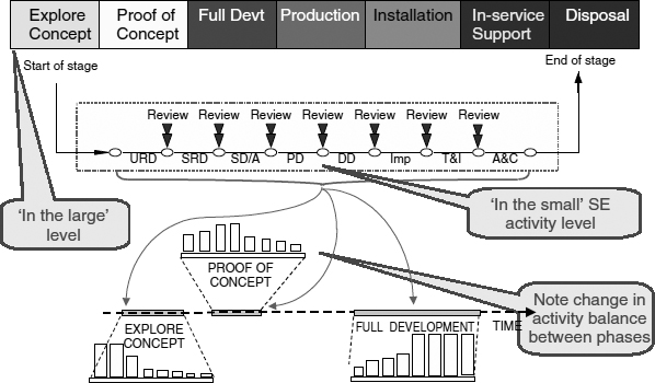
FIGURE 15.5 Changing activity balance between phases

FIGURE 15.6 Changing activity skills mix over time
Now, even if we allow that the requisite skills exist in type and number within each part of the organisation (admittedly a big assumption!), not being allowed (for whatever reason) to use the right skills mix (because they exist only somewhere else in the organisation) will harm the project. If we just use business analysts and requirements specialists during Explore Concept (and it is not unknown for organisations to behave in precisely this way), the output from the Explore Concept phase will be decidedly lopsided. Business cases will not be worth the paper they're written on. Think about it: who constructed the cost side of the cost/benefit equation? What assumptions were used? Do they bear any relationship to engineering reality?
Combining Models
It is possible to combine different ‘in the large’ models as necessary. For example, it would be quite realistic to combine the High-Risk Model with the Incremental Model in some way, for example by extracting the system architectural aspects of the project and creating a phase after Proof of Concept called, say, Baseline Architecture (or something equivalent) and then repeating the relevant aspects of Full Development, Installation, and Production once per Increment, thus building up to full functionality in stages.
This combined model is similar to the Rational Unified Process (RUP 2003) which is normally described in terms of the following four phases:
- Inception (similar to Explore Concept)
- Elaboration (similar to Proof of Concept + System Level Architecture)
- Construction (N increments delivered either internally or externally)
- Transition (similar to aspects of In-Service Support e.g. handover and user training)
One could go further and suppose that during In-Service Support, there should be an accommodation for multiple successive in-service enhancements and upgrades. Adaptation and inclusion of the Evolutionary Model might be the preferred way of incorporating this extension.
Extending this extension even further, each evolutionary upgrade might itself be designed, constructed, and delivered incrementally.
On another tack, we could conceive of a situation in which we decide that the Evolutionary Model is combined with the Incremental Model. In this situation, each successive version (see Figure 15.1) is delivered in distinct increments i.e. embed Figure 15.2 inside each version within Figure 15.1.
And so on.
Meta-Process
The preceding sections have suggested that specific process models should not be institutionalised within an organisation's process manuals, since this leads to process rigidity and inappropriate project shapes.
Instead, we should ‘go up’ a level in our thinking and think about what sort of guidance we could write to help someone generate and tailor a process relevant to any specific project. This ‘one level up’ type of thinking can be considered as a Systems Engineering Meta Process.
It can be depicted in Figure 15.7, as follows:
A good way of constructing this meta process is to try and characterise the project in terms of the questions raised in the context of each ‘in the large’ phase model discussed above. This can be thought of as an application of ‘storytelling’ to the meta-level system context. Here are the questions and their implications:
- Is there a business need to get the product to market in the shortest time possible?
- Yes
 Evolutionary Model
- Yes
- Is there a very rapid rate of technological evolution relative to design and delivery lead-times (implying very short product lifetimes)?
- Are customers prepared to accept the functionality that you and technology can offer in the short term, rather than waiting longer for a better solution? Are they likely to pay for successive versions?
- Yes Evolutionary Model
- Yes
- Can you tolerate loose technical linkage between successive versions of a sys-tem/product?
- Yes Evolutionary Model
- Yes
- Is there some reason why it is impossible to deliver total system functionality in one chunk. Do time or financial constraints mean a ‘salami slice’ approach is required? Can functionality be prioritised? Do functionality sub-sets make operational and business sense? Do successive increments have to dovetail perfectly?
- Yes Incremental Model
- Yes
- Do you really know at the outset what exactly the problem is, what the requirements are, what solutions might be relevant, or whether the stakeholders really know what they want?
- No High-Risk Model
- No
- Is likely candidate technology proven?
- No High-Risk Model
- No
- How confident are you about the validity of the requirements discovery process?
- Not very confident High-Risk Model
- Not very confident

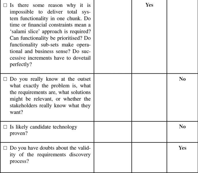
Alternatively, in tabular form:

Things are relatively straightforward if this question-and-answer approach yields a single mutually exclusive solution, that is, all the answers indicate exactly one of the options Evolutionary, Incremental, or High Risk. But what happens if one of the four other possibilities arises, that is,
- Evolutionary and Incremental
- Evolutionary and High Risk
- Incremental and High Risk
- Evolutionary, Incremental and High Risk?
Evolutionary and Incremental
The combination of Evolutionary and Incremental probably means that the Evolutionary Model dominates but that due to timescale or resource constraints, the full functionality of a version cannot be delivered all at once. However, getting some critical and useful initial functionality into the field makes business and marketing sense. Once this is achieved, the remaining increment(s) can be added. Schematically, this would look something like this:
Interpreting it the other way round (i.e. Incremental dominating with Evolutionary contained inside) does not seem to make much sense. You should check your logic!
For example,
- Increment 1
- Version 1.1
- Version 1.2
- …
- Version 1. N
- Increment 2
- Version 2.1
- Version 2.2
- …
- Version 2.N
- … Increment M
- Version M.1
- Version M.2
- …
- Version M.N
Evolutionary and High Risk
The combination of Evolutionary and High Risk only seems to make complete sense if the project falls predominantly into the High-Risk category and the evolutionary aspects relate to mid-life improvements and upgrades within In-Service Support. This would be implied by the following responses:
| Questions | Answers |
|
No |
|
No |
|
Yes |
|
Yes |
|
No |
|
No |
|
Yes |
The project structure would probably be as follows:
- Concept exploration
- Proof of Concept
- Full Development
- Production Installation
- In-Service Support:
- Version 2
- Version 3
- …
- Version N
However, suppose the responses are as follows:
| Questions | Answers |
|
Yes |
|
Yes |
|
No |
|
No |
|
Yes |
In this case you have a problem! You are faced with the challenge of designing, producing, and delivering a system in short order with high initial risks in the area of requirements and technology. This is very likely mission impossible and probably doomed to failure. You should ask yourself whether you are in the right business!
Incremental and High Risk
The combination of Incremental and High-Risk almost certainly means the High Risk model dominates with the Incremental aspect fitting inside it. So, you Explore Concept, do Proof of Concept and Baseline Architecture, then do Full Development, Installation, and Production Ntimes on an Incremental basis. Doing it the other way round does not seem to make much sense. As already mentioned, RUP seems to be similar to this.
The project structure would be as follows:
Evolutionary, Incremental and High Risk
The combination of Evolutionary, Incremental, and High Risk probably means that the situation as described in the previous section on Incremental and High Risk exists, but with the Evolutionary aspects confined to mid-life improvements and upgrades within In-Service Support. The project structure would be as follows:
- Concept exploration
- Proof of Concept
- Baseline Architecture
- Increment 1
- Full Development
- Production
- Installation
- In-Service Support
- Increment 2
- Full Development
- Production
- Installation
- In-Service Support
- …
- Increment N
- Full Development
- Production
- Installation
- In-Service Support
- Mid-life improvements and upgrades:
- Version 2
- Version 3
- …
- Version N
It could alternatively mean that:
- the project is predominantly High Risk;
- it has Evolutionary aspects confined to mid-life improvements and upgrades within In-Service Support;
- each mid-life improvement and upgrade is done Incrementally.
The project structure would probably be as follows:
- Concept exploration
- Proof of Concept
- Full Development
- Production
- Installation
- In-Service Support:
- Version 2
- Increment 2.1
- Increment 2.2
- …
- Increment 2.N
- Version 3
- Increment 3.1
- Increment 3.2
- …
- Increment 3.N
- …
- Version M
- Increment M.1
- Increment M.2
- …
- Increment M.N
- Version 2
But be careful, check that you are not in mission impossible mode again as described in the section on Evolutionary and High Risk!
CONCLUSION
This chapter has explored the idea of thinking about the system development life cycle in story form. Furthermore, it seems that a few simple stories can be composed in different ways to produce more complex process models.
The ideas discussed in this chapter started to form when I worked for a large UK company with a diverse assortment of projects employing a range of technologies. I had the job of trying to codify systems engineering knowledge and produce an in-house set of guidelines. The concept of separating the two levels of systems engineering process seemed to simplify things considerably, as did the realisation that there is no perfect ‘one size fits all’ process model. For those interested, the seeds of the thought processes contained here first saw light of day in Farncombe (1997).
KEYWORDS
Life cycle
Evolutionary (development)
Incremental (development)
Risk Reduction
Iteration
Systems Engineering
Tailoring
REFERENCES
Beck, K., Extreme Programming Explained, Addison-Wesley, 2000.
Booch, G., Object-Oriented Analysis and Design, with Applications, The Benjamin/Cummings Publishing Company, 1994.
Conger, S., The New Software Engineering, Wadsworth, 1994.
Farncombe, A., Tayloring (sic) systems engineering processes to project management circumstances, UK INCOSE Third Annual Symposium, Luton, U.K., 1997.
Mazza, C., Fairclough, J., Melton, B., De Pablo, D., Scheffer, A., and Stevens, R., Software Engineering Standards, Prentice Hall, 1994. Formerly the European Space Agency's PSS-05-0 Standards (Issue 2, 1991; BSSC version 1984)
Royce, W.W., Managing the development of large software systems: concepts and techniques, Proceedings of IEEE WESTCON, Los Angeles, CA, Chapter 3, 1970.
RUP, Rational Unified Process, IBM Rational Software, RUP 2003.06, 2003.
Sommerville, I., Software Engineering, 6th ed. Addison-Wesley, 2001.
Stevens, R., Brook, P., Jackson, K., and Arnold, S., Systems Engineering, Coping with Complexity, Prentice Hall, 1998.
RECOMMENDED READING
Ian Sommerville's Software Engineering (Sommerville 2001) is a good general overview of the need to manage project life cycles and the basic need to control risk.
The (ESA) Software Engineering Standards (Mazza 1994) offer a plain and practical introduction to the life cycle. While on the surface they are framed as pure ‘waterfall’ terms, in truth the activities are the ingredients of all life cycles. The descriptions of the component processes and the supporting templates also provide a useful foundation.