
CHAPTER 10
THE ROLE OF SCENARIOS IN CONTEXTUAL DESIGN: FROM USER OBSERVATIONS TO WORK REDESIGN TO USE CASES
Karen Holtzblatt
InContext Enterprises Inc., Maryland, USA
CONTEXTUAL DESIGN (CD) is a full customer-centered design process for system and product design, providing explicit steps and deliverables from initial discovery through system specification. Contextual Design is used to characterize a market or population, identify product and system concepts, and work out the details of the specific system definition. Contextual Design uses customer data throughout the process to drive design decisions. User scenarios and scenario-based reasoning is central to the CD process. But for good design, scenario-based reasoning must be alternated with model-based reasoning. In this chapter we talk about how customer data, scenarios, and models are used within the CD process to produce designs that work for people.
At its core, a scenario is a sequence of steps that defines a task performed to achieve an intent. Life is lived in a sequence, one moment at a time. When a person performs a task we observe sequential action. Although a person might consider multiple options before choosing, “consideration” is a step in a sequence. When we collect task data from multiple people, or even multiple instances of a task from the same person, we start to identify choice points or strategies. But we will only see this structure in the work1 when we step back from the actual activities observed and model the work. Model-based reasoning reveals structure. It lets us step outside the details of a particular instance and identify the structural dimensions of the work as it is revealed across multiple cases. Branching in a sequence of steps can be identified when we create a model of the work practice; it is not present in real life.
User tasks are one form of the sequential representations, or scenarios, necessary for good design. Redesigned work practices when represented as future scenarios are another. Even implementation design is dependent on sequential representation in the form of use case scenarios.
Good systems design, work redesign, and market or population characterization is dependent on an alternation between sequential or scenario-based reasoning and model-based reasoning. Sequential reasoning alone will not allow a team to step outside the “weeds” of the individual steps of a person or a system and see where restructuring can improve the work practice or system design. Models in the form of diagrams that represent the structure of the work, the work redesign, and the system give teams the big-picture view necessary to allow them to restructure the system and the work to best support the user population. A task focus alone will optimize redesign at the level of the task and the step. Model-based reasoning supported by an appropriate diagram gives teams the larger structural perspective they need to reinvent the work, both through process changes and by applying technology.
But a structural view alone will not deal with the real details necessary to get the work and the system definition right. Alternation between these two types of reasoning provides the necessary perspectives on the design activities to ensure a high-quality result. Contextual Design builds this alternation into a customer-centered design process.
APPLICABILITY
Because CD deals with the front end of design—from finding out who your customers are through testing a specific solution for them—it is equally applicable for commercial products sold into a market or business systems built by IT departments. Contextual Design has been successfully used to design business applications, consumer applications, enterprise software, products of all sorts for sale to a market, web pages and portals, wireless applications, and manufacturing applications. Contextual Design is appropriate for any size project; the method scales up and down to accommodate the scope of the problem.
Contextual Design is often described as excellent scaffolding because it works like a backbone into which other tools and techniques can be easily added. CD provides a series of techniques that can be incorporated into a company's standard methodology; among other things it produces artifacts and data that can feed existing requirements specification formats. CD works well for organizations putting ISO 9000 or SEI-compliant processes in place: well-defined steps and measurable deliverables support the requirements of those standards for defined, repeatable processes. For companies using the Rational Unified Process, CD supports and extends the business modeling and solution design disciplines during the Inception and Elaboration phases of any project following RUP.
POSITION IN THE LIFE CYCLE

Contextual Design maps to several components of the traditional life cycle approach. Importantly, it creates a new component—work practice redesign. Work practice redesign is a critical bridge between requirements discovery and requirements validation. Work redesign is an explicit step changing organizational and individual processes and the supporting systems. Systems often fail because there is not a clean separation between the design of the practice and the design of the system.
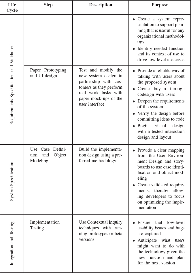
See Table 10.1, which defines the features of CD to see how it maps into the system life cycle. CD is not a clean waterfall process since validation, testing, and iteration with users occur throughout the process—when storyboards can be shared with stakeholders, during multiple rounds of mock-up interviews, and finally after running prototypes or beta versions are used to gather data on running systems.
KEY FEATURES
Contextual Design consists of the following key steps:
STRENGTHS
- Contextual Design ensures that real customer data drives every step of the design process
- Contextual Design is a scaffolding, easily supporting and integrating UML, use cases, personas, lab-based usability testing, X-programming, and other methodologies
- Contextual Design is a fully integrated step-by-step process that helps teams know exactly what to do so they move smoothly through the design process—from customer data to specific interaction design and to code
- Visual representations or diagrams that people can discuss, review, map, and eventually test with customers are provided.
- Contextual Design supports both large-scale and focused projects. The process can be tailored by altering project scope, number of users, number of models, and number of people needed to do the work.
- The User Environment Design supports prioritization for a coherent series of releases or for distributing coherent work to a team
- Contextual Design helps facilitate change management within businesses when they are rolling out new systems to their internal users. Because users are involved throughout the process, they start to buy in through their own participation.
- Contextual Design mitigates risk. CD encourages decision-making based on clear customer data and a tested design. Managers and developers know what to implement and what design will work for the real users. Software evaluation and platform decisions can be based on clearly defined system needs.
- Contextual Design recommends using a cross-functional team to do the design. Clear team processes foster creating a shared understanding of the customer and what to build—and a clear method for working successfully with each other.
TABLE 10.1 Contextual design steps mapped to the life cycle


WEAKNESSES
- Task analysis alone is not recommended for larger and more innovative projects. This means more modeling and data synthesis than some teams are accustomed to doing.
- Some organizations and teams think that a well-defined process slows down the work. Organizations that measure progress by lines of code may feel slowed down. CD deliberately holds off coding until the design, or a coherent part of the design is stabilized and tested—facilitating fast, focused development.
- Contextual Design relies on paper. Tracking and saving all the data, models, and other deliverables generated by CD can be an administrative burden. We have developed our CD Tools application to address this.
- Contextual Design requires some form of training and redefinition of roles, responsibilities, and processes. As such, it requires organizational change in companies that are currently engineering driven.
- Inexperienced people can have trouble recognizing when they've reached the point of diminishing returns. They may collect more data or go to deeper levels of detail than they need.
- People can get stuck in the system definition phase and lose sight of the importance of quickly getting back to the customer with a paper prototype.
- Contextual Design is a qualitative process. Although we can collect quantitative data as well (e.g., timing metrics and cost savings estimates), some people are not comfortable with a primarily qualitative process.
- Contextual Design is a team-based process. People and management are not always accustomed to allowing such explicit teamwork. Finding the space for a team room in traditional organizations can be challenging.
TECHNIQUE
Contextual Design is a customer-centered front-end design process that supports teams in using customer data to define products and systems for any technology platform. User scenarios derived from real customer data and scenario-based reasoning are central to the CD process. Scenario-based reasoning ensures that the details of the design are worked out. But scenario-based reasoning is balanced with model-based reasoning, which reveals the structure of the work, the redesign, and the system. It is the structural view and the model-based reasoning that drives innovative design and process solutions.
The CD process has been well described in our book Contextual Design: Defining Customer-Centered Systems (Beyer and Holtzblatt 1997); there is a shorter account in Holtzblatt (2002). Here each technique is briefly described in conjunction with the worked example to illustrate the way scenario-based reasoning and model-based reasoning are used with customer data throughout the design process. Table 10.2 summarizes the alternation of these processes.
TABLE 10.2 Contextual design steps alternate between scenario and model-based reasoning

TECHNIQUES AND WORKED EXAMPLE
For the purpose of illustrating the techniques, we use a design problem that we developed for training purposes: grocery shopping (InContext Enterprises 2003). This example is based on real customer data and produced an example design. We choose this design problem because it is easy for people to understand.
Shopping Design Problem: Our design team works for a company that wants to use technology to support families doing grocery shopping. We have lots of technology available to us, anything a consumer might use or access. We may think about combining technology with traditional or manual steps. Our charge is to develop an innovative new design.
Contextual Inquiry
To design a product or system that meets customers' real needs, the team must understand their customers and their work practice (see Terwilliger and Polson 1997 for related research). Work becomes so habitual to the people who do it that they often have difficulty articulating exactly what they do and why they do it (Goguen and Linde 1993). In a traditional interview when we ask people to tell us how they do an activity, they give us a summary story of what they believe they do or what they think they should do. These kinds of customer scenarios or typifications do not provide the detailed reliable customer data needed for design. Through Contextual Inquiry we conduct field interviews to collect real moment-by-moment sequences of activity.
A Contextual Inquiry interview is a one-on-one field data gathering technique. Team members observe people as they work and inquire into actions as they unfold to understand motivations and strategy. If designers watch people while they work, people do not have to articulate their own work practice. Field data overcomes the difficulties of discovering tacit information. Through observation, discussion, and retrospective accounts, Contextual Inquiry collects the real cases of work that a system has to support.
For the online grocery shopping design, our team conducted Contextual Inquiry interviews with customers who represent the target market. We observed them in their homes prior to shopping and at the grocery store (physical or online) while they did shopping to discover:
- How they prepare before going to shop
- How do they decide what to buy
- Where they go and what they do once at the grocery store
After each customer interview the data was heard and analyzed by the team in an interpretations session.
Interpretation Sessions
Contextual Interviews produce large amounts of customer data, all of which must be captured and shared with the team: user interface designers, engineers, documentation writers, usability specialists, internal business users, marketers, and business analysts. Traditional methods of sharing by presentations, in reports, or by email do not allow people to truly process the information or bring their perspectives to bear on the data. These summary reports also fail to capture the low-level of detail of work.
Interpretation sessions bring the cross-functional design team together to hear the whole story of each interview and capture the insights and data relevant to the design problem. Three to four people are needed to run an interpretation session. The team captures key issues that will be used to build the affinity diagram, draws work models, and develops a shared understanding of the customer's needs. It is in this context that the actual sequence models are captured.
For the shopping example, the team interpreted each customer interview, capturing the data by recording the key issues and all five work models for that user.
Work Modeling
Work models capture the work of individuals and organizations in diagrams. Work models are captured by modelers during the interpretation session: relevant data is recorded in each diagram as it is revealed during the retelling of the interviewing story.
The following five models provide different perspectives on how work is done. Because work itself is complex, no one model can capture all the dimensions of the work practice that a system must address. Each model represents a different “face” of the practice and reveals a different aspect of the structure of the work and its associated issues.
- The flow model depicts people's responsibilities and the communication and coordination required to support the work. The flow model reveals the actual human process used by a work-group or organization. The flow model is model-based because it shows how the players in the target population interact to get the work done irrespective of time or order. When consolidated, the flow model is the key model for driving the definition of the market or user population and for redesigning overall organizational and group process. The consolidated flow model describes and identifies the people who will be players in the future scenarios and the actors or role players in the use cases.
- The cultural model reveals the influences on a person, a group, or an organization, whether external to the company (such as the law) or internal company policies (standards). It reveals the cultural milieu in which the system will have to succeed. The cultural model supports a systemic view of work and so is also model-based. When consolidated the cultural model is the key model for identifying the value proposition for the system and for redesigning the values and forces within a work-group or organization.
- The physical model shows the physical layout of the work environment and the constraints it imposes on the design. The physical model captures the footsteps between places, the role of distance, and the usage of space. It shows the way people physically structure their work environment and workspace. Because the physical model captures the structure and flow of work as it is manifest in space, it also supports a systemic view of the work. When consolidated the physical model is the key model used to redesign the way distributed groups work, how space is used, how footsteps can be reduced, and how work can be segmented conceptually within the system.
- The sequence model is equivalent to a task analysis. It shows each step required to perform a task in order. A sequence model represents the activities of one player who will use the system. Along with the other models the sequence model also shows the breakdowns in the work. The consolidated sequence models become the basis for scenario-based reasoning and redesign at the level of the task itself.
- The artifact model shows how artifacts are structured and used during the performance of tasks. The artifact is another detailed model necessary to understand how to design or redesign online artifacts to better support the work. Analysis of existing artifacts identifies their intent, usage, structure, and information. The consolidated artifact model brings all the variations across users into one model so that they can be considered together for the redesign.
When planning a CD project, the team defines the models needed to address the scope of their project. Any project that plans to produce a user interface should use sequence models to provide the detailed cases that the system and the UI must support. The “actual” sequence model represents the real work practice of one user. It is a live “scenario of use.”
Figure 10.1 shows a sequence model for one customer, designated as U2. The steps U2 took to make her shopping list are on the left side of the model. At the top is the trigger, the stimulus or condition that caused the user to start this task. Sequence models supply the low-level, step-by-step details on how the work is accomplished. Any breakdowns or problems in doing the steps are also captured. Last, the sequence model captures the overall intent of the task and the intent of key steps. Since the purpose of user data is ultimately to redesign the work, capturing the steps and breakdowns is necessary but not sufficient. Why did the user even carry out this overall task? To do the task, why did she take a certain step or series of steps?
The “whys” are the customer intents. Work redesign is the result of changing the steps of the work to better achieve the intent through technology or work process simplification. We can modify, remove, and create new steps as long as the users can still achieve their fundamental intents and the business can accomplish its goals. The value of technology ultimately is to achieve the intent of our activities faster, cheaper, easier, and with more delight. The sequence model, by capturing the actual steps of a task, allows us to identify the intents and thus to redesign the work.

FIGURE 10.1 Sequence model for making a grocery shopping list
Use case modelers should recognize similarities between the use case artifact and the CD sequence model (e.g., triggers, event flows, etc). From the perspective of a structured design artifact, it is helpful to think of the CD sequence model as a stereotyped use case, extended to include things like event flow activity intents and breakdowns. Further, it is useful to recognize that CD sequences are really instances of use cases, achieving a traditional, generalized use case representation following the consolidation of each individually captured instance.
Consolidation
Consolidation brings data from individual customer interviews together so that the team can see common pattern and structure without losing individual variation. Consolidation of the work models is the process of stepping out of the details of an individual case to see the larger pattern of work as revealed across cases and people. Consolidated work models bring together each different type of work model separately, revealing common strategies and intents while retaining and organizing individual differences. The affinity diagram brings together the issues and insights captured in the interpretations sessions into a wall-sized, hierarchical diagram to reveal the scope of the problem.
Work model consolidation results in a set of diagrams that when taken together support model-based reasoning about the work practice itself. Because consolidated models segment work practice into coherent and meaningful chunks, the team is able to see, capture, and think about very complex and rich information. This clear organization of information about the practice and needs of the customer population supports and structures the team's redesign conversations. Team members can discuss changes in the model of work through the introduction of technology, redesigned tasks, roles, responsibilities, cultural values, and space as appropriate to the project scope and business goals.
Figure 10.2 shows a consolidated sequence model representing all users who made a shopping list as part of grocery shopping. There is a separate consolidated sequence model for each task in our grocery shopping design project, that is, making a shopping list, doing the shopping, and so on. Once the grocery shopping customer interviews and interpretations sessions were completed, the affinity diagram was built and all the work models were consolidated. To see an online view of the affinity diagram and other consolidated work models you can go to the team's Shopping Design Album at: http://www.incent.com/insite/shop/index.htm.
Sequences are consolidated by collecting together actual sequences with similar primary intents. Steps are grouped into chunks that represent activities. Steps within each activity are consolidated into abstract steps representing the detailed individual steps in each actual sequence model. Intents and breakdowns at the level of the task and the steps are also consolidated. The result is a single definition of the intents, steps, branches, strategies, and breakdowns for each task.
Work redesign is ultimately about redesigning the consolidated sequences. Whether the redesign eliminates or changes the steps or eliminates the entire sequence, knowing the steps and intents keeps the team honest. Redesign will better support the work if it “accounts for” each intent, trigger, and step. This does not mean leaving the work as it is; it means that the team has seen the current activity and has completely considered what will happen to it in the new work redesign. The consolidated sequence represents the as-is state of the process. It is critical as a guide for storyboarding, the to-be redesigned task.
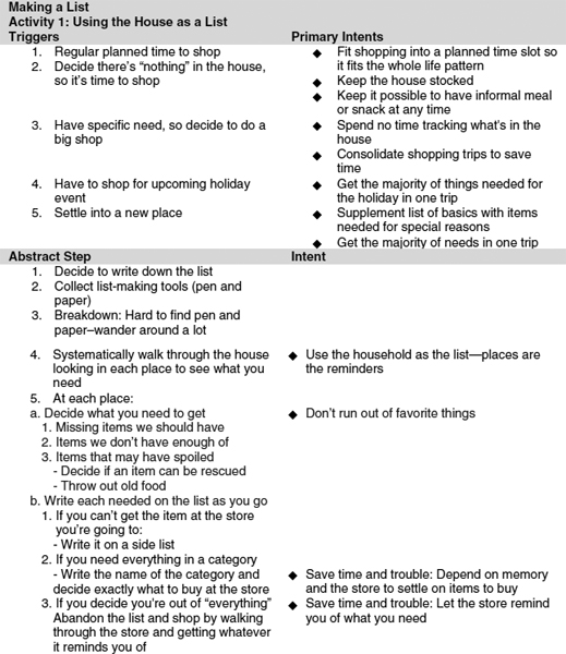
FIGURE 10.2 Portion of consolidated sequence model for making a grocery shopping list. The full consolidated list-making sequence consists of several activities and associated abstracted steps, representing all users the team interviewed. Here you see a portion of the consolidated sequence model showing one of its activities: Using the House as a List. Each abstract step you see is a consolidation that represents a step that at least one user performed
Visioning
Central to CD is the idea that system design is really work practice redesign. New products and system concepts; requirements for enterprise and business systems; and the identification of new features for existing systems, best emerge from a focus on redesigning the work given technological and organizational possibilities. Visioning is a high-level story of the “new world” of your customer population, achieving the task intents of the sequence model; using redesigned artifacts from the artifact model; playing the redesigned roles in the flow model; transforming the cultural forces within the cultural model; within the constraints of the physical model in order to overcome the issues identified in the affinity diagram. In other words, the vision synthesizes the findings and implications of the customer data into a productive business response.
Visioning focuses the team on inventing how technology can help people get their jobs done, rather than on what could be done with technology without considering the impact on people's real lives. Design of technology is first design of the “big picture” story of the future showing how manual practices, human interactions, and other tools come together within the planned system or product to better support the whole practice.
During a visioning session, the cross-functional team tells the story of how work will be done in the future. This is a group story-telling activity where team members build on and add to each other's ideas much like friends around a camp fire constructing ghost stories. One team member captures the team's ideas on a flip chart page using pictures to illustrate the concepts and synthesize ideas. During a visioning session, the team moves through the story of different role players in different contexts doing different tasks. Evaluation of ideas is put off until after several visions are generated.
During a vision, the individual story threads are synthesized in real time onto a page visible to all. Although the individual team members are speaking and thinking the redesign sequentially, the vision diagram allows the team to see the new work practice and associated technology from a model-based perspective. This model-based view evolves visually during the vision session and encourages the team to see and reuse emerging system and organizational concepts. The vision is a story generated from scenario-based reasoning, but its ultimate representation, the vision drawing, is a model-based view of the new work practice synthesizing changes in the work structure and the technology into one high-level picture.
Our shopping team started by walking their consolidated data, discussing their design ideas informally, and identifying the issues they wanted to address. The team then generated multiple visions. Some dealt with how the shopping list was made, others focused on shopping itself, and others brought in support of other errand running tasks associated with grocery shopping. Some visions imagined in-store solutions; others imagined web-based solutions in the home. The team then evaluated the visions, explicitly identifying each one's strengths and weaknesses in light of the customer data, business goals, and technological ease. Weaknesses were overcome. The best parts of each vision were synthesized in the consolidated vision you see in Figure 10.3. This consolidated vision simultaneously represents a very high-level future scenario and when viewed on a single page a systemic model-based view of the new socio-technical system.

FIGURE 10.3 Complete, synthesized vision for online grocery shopping product
Storyboarding
The vision does not work out the details of each case or task. Nor does it clearly sort out what is technically doable or define the function that must appear in a user interface or the function to be performed by the system. Storyboarding works out the details of the vision, guided principally by the consolidated sequences representing the key tasks that the system has to support.
Storyboards are equivalent to future scenarios (Rheinfrank and Evenson 1996) or high-level use case instances and may be represented in standard use case document structure and Unified Modeling Language notation. (See Figure 10.4 for an example of a storyboard cell and its UML equivalent.) But we choose to represent the redesigned work in frame-by-frame drawings. They include manual steps, rough user interface components showing function, system activity and automation, and even documentation use.

FIGURE 10.4 Storyboard cell 1. Four of the five triggers are accounted for in this storyboard. The case of the fifth trigger, “Settle into a new place,” is too different from the others, and needs to be worked out in its own storyboard. The customer in this case is playing the role of the household's “head chef” – the person who decides what meals will be prepared. This is a process step; it shows that the context of the work will not change, but the tools to respond to the work (getting the bar code pen) will be different
By working with multiple teams, we have learned that the best system design comes from this type of visual representation of the to-be models of work. Text versions of a scenario or simple user interface drawings alone fail to consider all the dimensions of the new work practice. Use case and object modelers are trained to use the text-intensive use case characterization of the redesigned work. We find that this ultimately focuses them too much on system activities and business rules and not enough on necessary human processes and user interface function. But user interface designers who are concerned primarily with the interaction design tend to overlook the system steps and over-focus on UI detail. They get stuck prematurely in detailed discussions of layout that will become irrelevant when the implications of multiple scenarios of use are worked through.
One key principle of CD is to use the right representational form for the design conversation the team is trying to have. Even though it might be possible to represent the storyboard concepts with UML models, use cases and instances, a series of UI drawings or even a high-level business process drawing—none of these individual representations encourages the team to think about all these factors simultaneously. Storyboards by their very nature ensure synthetic sequential thinking and thereby a more complete design for the user, especially when guided both by the vision and the consolidated sequences. Storyboards also provide a conceptual common denominator for design discussions with users; it is much more likely that a user will grasp the metaphor of a storyboard (e.g., as used in the creation of animations, comic books and movies) over more abstract modeling symbologies or unfamiliar web design artifacts. UI screen mock-ups encourage users to focus the conversation on UI aesthetics (color palettes, widget choice and placement, etc.) rather than work practice redesign.

FIGURE 10.5 Storyboard cell 2. This cell traces back to the step for adding items to the list when we are running low on them, showing how the work will be redesigned. The swipe will enter the milk brand on the list. The system design creates a problem – paper gives feedback that the item is recorded. The new system must account for that implied function or break the work. As such, the team invented the “beep” to show that the item has been received. But the team also anticipates the potential breakdown when the user moves away from the flat panel and can't hear the beep

FIGURE 10.6 Storyboard cell 3. Storyboard cells also account for system steps as well as user steps. Notice what the system is doing automatically for the user. It is tracking historical purchases, recording and reconciling brands, and recording how much of each item to add to the list. This system step replaces what people are currently doing manually through personal memory and walking through the house. However, it improves the current process. For example, human memory no longer has to be relied upon, it takes care of household members adding to the list who don't know what should be in the house and don't recognize what's missing, and no one needs to walk around if they don't want to
Driving scenarios from consolidated data ensures that different strategies for doing a task will be considered and that the design will support the different routes that real people use to achieve their intent. Figure 10.4 through Figure 10.7 show four cells of one storyboard for our online grocery shopping vision. This storyboard, usually hand drawn, works out the portion of the vision where we redesign how the customer makes the grocery shopping list. We've placed next to each storyboard frame an excerpt of the consolidated sequence that it supports, with a checkmark (√) for each trigger and step that is being accounted for. Our design must ultimately account for each step, trigger, and intent in the set of consolidated sequences that represent the task within the project scope. For any system, multiple storyboards will be generated to cover the various cases. Box 1 shows the same storyboard using UML.
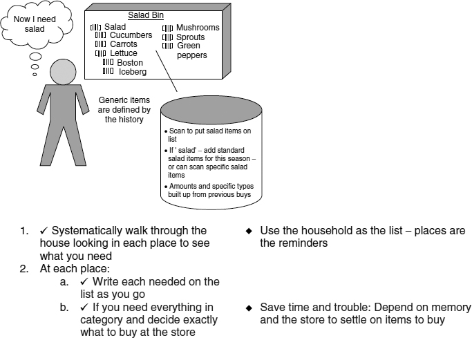
FIGURE 10.7 Storyboard cell 4. The consolidated sequence model shows that users think of some food items as part of a large category. For example, individual produce items can be in the category of “salad.” The user's redesigned work will let him pick an item or a category and the system will know what he likes and what is in season
Box 1 The same task defined as a use case

Use Case Name: Make Shopping List
Use Case ID: UC14
Actors
- Head Chef
Preconditions
- Use case “Set up On-Line Grocery Shopping System” (UC01) has been completed successfully
Triggers
- Regular shopping time is approaching
- Current Food Item supply is running low
- A specific, required Food Item is missing
- A period of high Food Item demand (e.g., a holiday) is approaching
Primary Flow of Events
- The use case begins when the Head Chef decides to generate a Shopping List.
- The Head Chef locates the Bar Code Pen.
- The Head Chef walks to a House Location.
- If the House Location stimulates recognition of need for a Food Item (e.g., Food Items in short supply, spoiled Items, etc.), the Head Chef swipes the Bar Code Pen across the Food Item package's Bar Code.
- The Bar Code Pen transmits the Food Item's Bar Code to the System (use use case “Transmit Food Item Bar Code” [UC23]).
- The system adds the Food Item Bar Code to the Historical Purchases database for a single Quantity Unit.
- The system confirms successful Bar Code transmission via the Audio Confirmation Signal.
- The system displays the new Food Item on the Flat Panel Screen and the use case ends.
Postconditions
- A new Shopping List Food Item is displayed on the Flat Panel Screen
- The Food Item entry is persisted in the Historical Purchases database
Alternate Flow of Events
- If The Head Chef has relocated and is stocking Food Items for the first time, use use case “Make Post-Relocation Shopping List” (UC15)
- At the end of Step 8, if there are more House Locations left to explore, the Head Chef iterates Steps 3 through 8.
- In Step 7, if the Quantity Unit or Brand Information is ambiguous, use use case “Resolve Ambiguous Quantity Unit or Brand Information” (UC34).
- After Step 7, if the Head Chef desires a Quantity Unit greater than one, she may scan the Food Item Bar Code multiple times to appropriately increment the Quantity Unit.
- If there are no Food Item entries in the Historical Purchase Database, the Head Chef may provide entries via old Purchase Receipts.
Issues
- In Step 6, the use case model must account for the possibility of the Head Chef being out of auditory range for the Auditory Confirmation Signal.
User Environment Design
A good product, system, or web page must have the appropriate function and structure to support a natural workflow within it. System design really has three layers. The user interface accesses the function, structure, and flow necessary to support the user's redesigned work. The implementation (object model) makes that function, structure, and flow happen. But the core of a product is that middle layer: the explicit work the system is performing. Just as architects draw floor plans to see the structure and flow of a house, designers need to see the “floor plan” of their new system. Hidden within the storyboards are the implications for the system floor plan—the User Environment Design (UED).
The UED formalism represents a set of “focus areas” or places in the system that provide support for coherent activities. A place might be a window, web page, dialog box, or pane. The UED shows each part of the system, how it supports the customer's work, exactly what function is available in that part, and how the customer gets to and from other parts of the system—without tying this structure to any particular user interface or implementation design. The function in the UED drives functional specification and implementation level use cases. The UED supports model-based reasoning about the system structure and function.
Figure 10.8 shows the main parts of the UED formalism. Each focus area is a place that defines the purpose, functions, and work objects to be accessed from that place. Links from one focus area to another define the flow within the system that the user can traverse. Double links mean that the user needs to be able to work in one focus area in the context of another. Hidden focus areas call out new automatic system function and business rules that now support work that was previously manual.
Any vision implies multiple scenarios to fulfill the vision. Customer data shows us that multiple roles doing multiple tasks will use the system. No system should be built around one storyboard or one future scenario. Just as a kitchen supports multiple scenarios of cooking (the quick pizza, the holiday dinner, the summer barbeque), a system supports multiple scenarios of use. In our homes, we naturally “move things around” and “learn from experience” as we design and redesign our spaces implicitly and explicitly. A good kitchen has all the functions, objects, and flow needed to support any cooking scenario. Similarly, a good system defines places where all the function, objects, and flow is present to support scenarios of use.

FIGURE 10.8 Formalism for user environment design focus areas
In creating a UED, the team uses the anticipated scenarios of use: the future scenarios or storyboards. They walk the storyboards and abstract out the implications of what the system needs to provide. As the implications of storyboard after storyboard are rolled into the UED creating focus areas, function, and links the team starts to see the best way to structure the system. The result is not a wizard-like, lock-step design but rather the definition of coherent places within which functions and objects may be accessed in any order. The sequential thinking of storyboarding drives the model-based thinking of the UED and results in a useful model of the system to support planning.
The UED is both the system work model and a simple definition of the functional system requirements. Because teams can simultaneously see all the parts of the system and how they relate, they can distribute work to individuals without fear of stovepipe design. And they have a big system picture from which to plan the rollout by carving up the focus areas into coherent releases.
Here's how the online grocery shopping team began to walk their storyboard cells. You'll see a portion of their completed UED in Figure 10.12. This example is for a new product. If you already have an existing product or system, you can first build a reverse UED to see how your existing system is structured. From there you can decide whether to use the reverse UED as the base of the new system, building on it and changing it in response to the storyboards. Or you can start a new UED and reuse function as it is called for by your storyboards.
Storyboard cell 1 (Figure 10.9) situates the story about making the grocery shopping list. Because our system is a mixture of hardware and software, some focus areas in the UED will represent physical hardware places as well as software screens. At this first cell the team is beginning to think about how work will play out, but is not ready yet to create a focus area.

FIGURE 10.9 Storyboard cell 1

FIGURE 10.10 Storyboard cell 2
In storyboard cell 2 (Figure 10.10) the user swipes the milk's barcode with the barcode reading pen. In response, he hears an auditory beep. The brand of the milk and the quantity come from the bar code. Clearly, the function needs to be documented in the UED. The team created a hardware focus area called Bar Code Scan with a user-invoked function to scan a bar code. They also created a software focus area called Manage Shopping Order and gave it an automatic function of emitting an auditory signal when the scan is successful. The system structure calls for these two focus areas to be linked to one another.
Storyboard cell 3 (Figure 10.11) has multiple functions, all automatically performed by the system. This cell leads the team to create a system focus area called Household Historian. System focus areas are not used by the user; all of the functions there are automatic and take place behind the scenes. The Household Historian focus area is linked to the Manage Shopping Order focus area.

FIGURE 10.11 Storyboard cell 3
The process for generating the UED continues in this manner, using the discussion of each cell in the storyboard to identify and capture new focus areas and add to existing focus areas.
Paper Prototyping, Mock-Up Interviews and Initial User Interface Design
The initial UED is the team's working hypothesis of how the system should support and extend the customers' work. But they need to stabilize the design, fill out its function, and be sure that what they are proposing will really work for customers. To do this we need a way to extend and test the proposed system with users in their real work situations. Paper prototyping allows us to do this.
Paper mock-ups and paper mock-up interviews are now used everywhere for user interface development, although this was not so when we first developed CD (Kyng's article (1998) is the classic on this topic. Snyder's book (2003) is a more recent resource). Paper mock-up interviews work because users understand user interfaces. They do not understand models like the UED or OO (Ehn 1988). Nor can they easily imagine a new work practice from storyboard review. After all, if the customers' awareness of their work is tacit, if they don't have a systemic view of how their work fits into the larger work of the work group or organization, they are not going to be able to articulate what might work and might not work within a meeting setting.
In Contextual Design we bring low-fidelity, hand-drawn paper prototypes out into the field and engage customers in “using” the new system by walking through real cases of their work. They walk through tasks that they have to do that day or that they have recently completed, inputting and viewing information, clicking on buttons and generally moving through the paper system while they perform a necessary task. Again, we use live scenarios collected within the real work context to test our system design.
The team brings additional mock-up parts so that in the moment they can add function, move around the focus areas, rename buttons, and codesign the system with the user. Needed change and function emerge as the user tries to use the new system to accomplish real tasks. The low-fidelity representation makes it clear that icons, layouts, and other interface details are not the central purpose of the interviews. This invites codesign and keeps the user focused on testing structure and function.
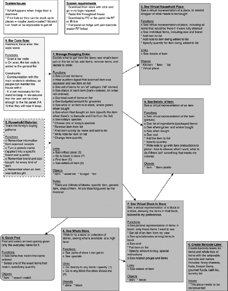
FIGURE 10.12 Portion of user environment design for the online grocery shopping product
After the design has been tested with three to four users, the team redesigns to reflect the feedback. The UED is updated, restructured as necessary, and functions are described in increasingly more details. After three rounds of mock-up interviews, the UED stabilizes and the interaction design layout and basic usability have been tested and validated. Multiple rounds of interviews and iterations drive testing at increasing levels of detail: structural issues to user interface layout to detailed user interaction.
After this process, the shopping team knew that they had a system structure that worked for their customers. They were ready for final interaction design, real visual design, and object modeling.
Using Contextual Design Deliverables to Generate Use Cases and Implementation Models
Once our online grocery shopping team finished the rounds of prototype interviews, their UED is also the foundation of their functional specification. It defines exactly what functions the system will provide and how they will behave. Paper prototype iterations ensure that the function definitions are complete and correct for the users. The UED shows the structural organization of the system from the user's point of view. Nonfunctional requirements driven by the users (speed, platform, compatibility with other systems, and so forth) are captured as constraints on the UED. Nonfunctional requirements driven by the business are added to the UED for a complete specification of the system.
The UED is also the source document for the next step in systems design, usually accomplished by writing use cases. Regardless of which formalism you follow for writing use cases (Cockburn 2001, Constantine and Lockwood 2001, and Peter Haumer in Chapter 12, Use Case-Based Software Development) offer useful examples), the UED provides the information you need. System function and behavior has already been defined, so these use cases can focus on showing how the system will provide the behavior specified in the UED. Each use case can be focused on a single system task (e.g. scan an item into our grocery system) because the coherence of the whole user task (shop for groceries) is guaranteed by the storyboard and UED.
Use cases are built using scenario-based reasoning. They drive the development of the object model representing the implementation of the system through an analysis that uses model-based reasoning. Just as the structure of the system as experienced by the user needs to be driven by the vision, the implementation object model must be driven by the UED if it is to be implemented correctly. Storyboards “stitch together” the vision and UED, showing how each element of the vision is implemented by a system component that keeps the work practice coherent. In the same way use cases show how implementation components deliver the behavior defined in the UED, which keeps the system coherent. The design thinking process and alternation between scenario and model-based reasoning is parallel.
A use case's preconditions are derived from the function definition and from the scenario that the use case implements. Business rules are defined by hidden focus areas in the UED, and by the automatic function it provides. The design team can check for completeness of the use cases against the UED and storyboards: every function in the UED and every situation covered by the storyboards should be reflected in one of the use cases.

FIGURE 10.13 A UML sequence diagram derived from objects as specified in the UED
Proceeding to implementation in this way ensures that the customer-centered focus of the design is maintained as the team moves to implementation. The functions in each case can be tracked back to the user data, helping to ensure that the team does not manufacture functionality irrelevant to the customer's work practice. Being tied to customer data allows the team to invent and redesign work practice, but keeps them honest and focused.
Figure 10.13 shows a UML sequence showing the implementation enabling the use case Make Shopping List as detailed above. Note that class, collaboration and activity diagrams may also be created using the sequential and structural modeling provided by storyboards and the UED. By using the CD models for work redesign, the transition into industry standard modeling notations (UML) and process frameworks (Rational Unified Process) is a natural one. Standard RUP artifacts—driven by designs based on user data—bridge the communication gap between standard system architecture and model-driven software engineers and user-centered designers. As the (scenario-based) sequence diagram above shows, implementation design simply continues the alternation of scenario and model-based reasoning that started during requirements analysis.
LESSONS LEARNT
We like to say that Contextual Design has been designed with Contextual Design. We are always in a state of continuous improvement. Much of how we run meetings, consolidate customer data, and even model the work and system has been generated over the years in response to the needs of teams and their projects. We started the development of our CD Tools application because teams were losing their paper data and were collecting the same data over and over instead of reusing it. We started defining shorter, more-focused variants of the full CD process to help teams accommodate differences in project scope and organizational constraints like time and human resources. We worked out ways to support small, two-person teams with adjunct resources and very large teams that need to communicate and build buy-in with many stakeholders. We integrated metrics and timing data to help teams anticipate and show productivity gains. And we help teams integrate the techniques of CD into their existing life cycle and corporate software processes.
But our biggest lesson learned is that customer field data can't be traded off. Many of the CD techniques for modeling, representing the system, and working out design concepts and future scenarios can lend structure to the design process. But through painful experience we have learned that without real user data collected through a well-defined process teams argue about who is right and what is needed. Without data, teams and decision makers have no basis for choosing one product, feature, or rollout plan over another. And without data companies fail to see and agree upon their opportunities for new product concepts and business solutions. Contextual Design is a powerful and reliable process because it is grounded in the detailed customer data that designers really need. The most important thing a team can do is to go to the field, collect those real scenarios of use, and build their design upon them.
COMPARISONS
We are often asked to compare Contextual Design to other methods categorized as Participatory Design, particularly Extreme Programming (Xprogramming 2003) and other Agile Software Development methods (Manifesto for Agile Software, 2001) (see Chapter 13, User Stories in Agile Software Development, by Kent Beck and David West). Agile methods focus on improving the development process once the system's requirements have been defined. Contextual Design focuses on defining those requirements—so the two approaches dovetail very neatly. And they each seek to make the customer the center of the design instead of the developers or the implementation. However, how we achieve this value is markedly different.
Agile methods involve the customer by putting one or more users on the team full-time. The customer is then on-site with the developers throughout development. The customer is a representative of the business client, serving as an active, ongoing resource, telling stories of use and helping to prioritize work. But Agile teams recognize that customers are not designers, and that they need to add additional people with user interface, graphics, and user experience design skill.
Contextual Design teams can also have customers on the team, and this can be effective. However, the customer data that informs the design is collected through the Contextual Inquiry interviews. Only by seeing the true context and details of use can the stories of use be derived.
Because Agile methods are focused on fixing the development practice through rapid iterations, they don't attempt to find common patterns or structural variations in work practice. This limits the scope of the resulting solution. Basing the design on the stories of one, two, or even three customers will likely not account for all the variations that matter.
Some proponents of Agile methods (www.xprogramming.com is a good source for information) recognize that the role of the customer in XP is to be the voice of the business—not the voice of requirements or design. As such, the customer's role is to make the business decisions about what features to implement when and to track user response to implemented features. XP is defining a software development process not a software requirements and user experience design process. When we work with our clients using Agile methods we include working with field data, which then drives storyboarding of the new system, or parts of the new system. It is these storyboard stories that are being implemented within each round of XP. Continuing in the spirit of the XP process, we recommend scoping the data collected and simplifying the design steps when working with a company implementing an XP process to stay one step ahead of the programming team.
There is more commonality in another shared value of Contextual Design and XP/Agile: the belief in the value of teamwork and self-directed teams (www.xprogramming.com and www.agilemanifesto.org both describe guiding principles). Both methods emphasize that being on a team does not mean that you work by yourself and periodically come together with other team members. Rather, work is done in pairs or subteams. Both methods also have the team reflecting at regular intervals on how to be more effective, immediately followed by it tuning and adjusting its behavior.
Contextual Design differs from other Participatory Design methods by introducing more formality into the process of defining what the system is to do. Many methods exist for working with users at different points in the design process; for example Ellen Gottesdiener's workshop facilitation techniques—see Chapter 5 in this volume. In contrast to some approaches that cover only part of the life cycle, Contextual Design provides a sequence of well-defined methods for working with users and user data to produce a result that is documented in a formalism that can drive the rest of the software engineering process. As such, it provides structure to a heretofore unstructured piece of the process—structure that can be used as is, modeled in the RUP or adapted to the software engineering method of choice.
KEYWORDS
Contextual Design
Customer-Centered Design
Contextual Inquiry
Work Models
Storyboards
User Environment Design
Requirements Analysis
Requirements Definition
REFERENCES
Beyer, H. and Holtzblatt, K., Contextual Design: Defining Customer-Centered Systems, Morgan Kaufmann Publishers, 1997.
Cockburn, A., Writing Effective Use Cases, Addison-Wesley, 2001.
Constantine, L. and Lockwood, L., Structure and style in use cases for user interface design, in M. van Harmelen (Ed.), Object-Modeling and User Interface Design, Addison-Wesley, 2001.
Ehn, P., Work-Oriented Design of Computer Artifacts, Gummessons, Falkoping, Sweden, 1988, international distribution by Almqvist & Wiksell International, also Coronet Books, Philadelphia, PA.
Goguen, J. and Linde, C., Techniques for requirements elicitation, Proceedings of the 1993 IEEE International Symposium on Requirements Engineering, San Diego, CA, January 4–6, 1993, p. 152; IEEE Computer Society Press, Los Alamitos, CA.
Holtzblatt, K., Contextual design, in J. Jacko and A. Sears (Eds.), The Human–Computer Interaction Handbook: Fundamentals, Evolving Technologies and Emerging Applications (Human Factors and Ergonomics), Lawrence Erlbaum Associates, 2002.
InContext Enterprises, Shopping Design Album, 2003, http://www.incent.com/insite/shop/index.htm
Kyng, M., Designing for a dollar a day, Proceedings of the Conference on Computer-Supported Cooperative Work, Portland, OR, September 26–28, 1988, p. 178.
Manifesto for Agile Software, 2001, http://www.agilesoftware.org
Rheinfrank, J. and Evenson, S., Design languages, in T. Winograd (Ed.), Bringing Design to Software, ACM Press, New York, 1996, p. 77.
Snyder, C., Paper Prototyping: The Fast and Easy Way to Design and Refine User Interfaces, Morgan Kaufmann Publishers, 2003.
Terwilliger, R. and Polson, P., Relationships between users' and interfaces' task representations, in CHI '97 Conference Proceedings, Atlanta, GA, March 22–27, 1997, p. 99; ACM, New York.
Xprogramming.com an Extreme Programming Resource, 2003, http://www.xprogramming.com
RECOMMENDED READINGS
Beyer, H., Calling down the lightning, IEEE Software, 11(5), 106, 1994. This column discusses the nature of creativity, what drives creativity, and what gets in the way. It uses the development of the spreadsheet as an example, showing that close knowledge of the customer is critical to making invention happen.
Beyer, H., Where do the objects come from?, Software Development '93 Fall Proceedings, Boston MA, August 1993. This paper dissects the process of going from object-oriented analysis to object-oriented design to show why it is difficult. The design of the overall system is identified as a missing step, and ways to re-introduce that step are discussed.
Beyer, H. and Holtzblatt, K., Apprenticing with the customer: a collaborative approach to requirements definition, Communications of the ACM, 38 (5), 45–52, 1995. This article discusses how to gather data from customers in one-on-one interviews through Contextual Inquiry. It is one of the two primary discussions of how to do Contextual Inquiry (the other is “Contextual Inquiry: A Participatory Technique for System Design,” by K. Holtzblatt and S. Jones).
Beyer, H. and Holtzblatt, K. Contextual Design: Defining Customer-Centered Systems, Morgan Kaufmann Publishers, 1997. This is the basic book describing the full Contextual Design process.
Beyer, H. and Holtzblatt, K. Contextual design, Interactions, 6(1), 32, 1999. This is an overview of Contextual Design with a focus on how to scale the process to fit the design process.
Holtzblatt, K., If we're a team, why don't we act like one?, Interactions, 1(3), 17, 1994. This column describes some of the problems of working in teams, showing why they arise and why working in teams is hard. It describes some of the interpersonal problems that cause teams to break down, and suggests strategies for handling them.
Holtzblatt, K., Contextual design, in J., Jacko and A. Sears (Eds.), The Human-Computer Interaction Handbook: Fundamentals, Evolving Technologies and Emerging Applications (Human Factors and Ergonomics), Lawrence Erlbaum Associates, 2002. This chapter provides an overview of the Contextual Design process along with key issues and answers to questions that are often asked about the practicalities of using the method within organisations.
Holtzblatt, K. and Beyer, H., Making customer-centered design work for teams, Communications of the ACM, 36 (10), 92103, 1993. This was the first article on Contextual Design published. It's a good and reasonably concise description of the process.
Holtzblatt, K. and Jones, S., Contextual inquiry: a participatory technique for system design, in A. Namioka and D. Schuler (Eds.), Participatory Design: Principles and Practice, Lawrence Earlbaum Publishers, Hillsdale, NJ, 1993. This article is the first published description of Contextual Inquiry. It describes the process, including three of the four interviewing principles, the interpretation session, and affinity diagrams.
Wixon, D. and Ramey, J (Eds.), Field Methods for Software and Systems Design, John Wiley & Sons, New York, 1996. This book describes the experience of several different practitioners using field methods. Several people who have used Contextual Inquiry and Contextual Design have written chapters describing their experiences. This is a good resource for anyone wanting to adopt customer-centred methods in their own organisation.
1 I use the word “work” and “work practice” to denote any form of life activity: business tasks, consumer tasks, and leisure tasks.