
CHAPTER 20
SCENARIOS IN RAIL ROLLING STOCK WITH REVEAL
Alistair Mavin
Praxis Critical Systems Limited, London, UK
THIS CASE Study chapter reports on a project with a major international rail rolling stock manufacturer during requirements elicitation and system specification for new metro Trains. The project used the Praxis REVEAL1 requirements engineering method.
Scenarios were used to analyse Train requirements to derive specifications and domain knowledge. The same scenarios were then used as the contextual glue to show that the requirements had been satisfied by the specifications, given the domain assumptions. The scenarios were, therefore, a key part of the Satisfaction Argument used to show that the solution will satisfy the requirement. Similarly, scenarios were used in the analysis of Train specifications to derive requirements for the sub-systems, which also uncovered further domain knowledge.
The process produced Train specifications that were written at the right level of granularity. During the development of activity diagrams, engineers tended to write simple descriptions of the external behaviour of the system as a black box. Previously, they had tended to go into the detail of specifications too early.
The scenarios explicitly showed dependencies on domain assumptions, as well as dependencies between different sub-systems. This visibility helped sub-system suppliers to understand the environment in which their products would be used. Using this process, the sub-system requirements contained all relevant information, and only relevant information. This made it easier for sub-system suppliers to respond, and for the client to assess their responses.
APPLICABILITY
The client designs Trains to satisfy both high-level customer requirements and rigorous rail standards. The new Train is a complex system of systems. Train sub-systems such as Car bodies, Bogies, and Bodyside Doors are specified and procured from third-party suppliers located all over the world. The client is responsible for ensuring that the systems can be built into a working Train.
REVEAL has been applied widely in the Rail, Aerospace, Defence, Telecomms, Finance, Nuclear, and other industries, mainly for real time control applications. REVEAL has also been applied to business requirements, to help define product strategy and during the analysis and assessment of bids. Scenarios are not a mandatory part of the REVEAL method, but are often used to explore operational and maintenance requirements.
POSITION IN THE LIFE CYCLE
![]()
KEY FEATURES
Scenarios were used to situate the requirements, specifications, and domain knowledge within the context of use of the system being developed. Scenarios were used to address requirements for discrete events such as starting and stopping Trains in a range of operating modes. One scenario was written for each requirement. Each scenario consisted of a set of End-to-End conditions and an activity diagram.
Each event in the Train swimlane was represented in the requirements database as a Train specification (to be further elaborated into requirements on Train sub-systems). Each event in any other swimlane corresponded with a domain knowledge statement in the database about that domain entity (such as Train Driver, Passenger, Automatic Train Control).
All statements are categorised as being Requirement, Specification, or Domain Knowledge. In REVEAL this is called the Separation of Concerns.
A central feature of the REVEAL method is the notion of the Satisfaction Argument. A Satisfaction Argument is written to show that the system specifications are sufficient to satisfy the system requirement, as long as the domain statements hold true. For a good introduction to the principles of REVEAL, see the Will it work? paper (Hammond, Rawlings and Hall 2001).
Failure conditions for each scenario were not formally considered as part of this project. However, a checklist of What-if questions was used to investigate any possible breaks in the scenario thread. This was a simple application of the concepts used in the ART-SCENE Scenario Presenter (Mavin and Maiden 2003).
STRENGTHS
Scenarios are easy to understand and easy for engineers to write, without the need to learn a complex new notation. This helps with getting projects off to a strong start, as scenarios can be used on day one.
Scenarios are written in the language of the engineers, who are experts in the domain. This focuses the analysis on realistic situations and encourages buy-in from stakeholders.
Scenarios help with scoping the system. Only domain entities included on the Rich Context Diagram can be included in the activity diagrams. The rigour that this brings promotes the consistent use of terminology.
Train specifications, sub-system requirements, and domain knowledge are contextualised by the scenario. By embedding them in a scenario, it is easier to see why they are necessary and why they take a particular form. The activity diagram provides an easy to understand single-page representation of how the system will operate in a particular set of circumstances. It also documents how the environment around the system is expected to behave. The activity diagram thus provides a coherent description of the expected interaction between the system and its environment.
This approach helps drive out issues of ownership of data and functions between sub-systems and therefore between different suppliers. The demarcation between subsystems is clearly defined by the use of swimlanes to show which entity carries out any particular activity.
The scenario model supports the Satisfaction Argument, and as such is a simple one-page proof that the requirement will be satisfied. The Satisfaction Argument states that the Specifications will be sufficient to satisfy the Requirement so long as the Domain Statements hold true. The scenario shows how these statements are related and therefore proves that the requirement will be satisfied.
The Satisfaction Argument is automatically built as the activity diagram is being developed during elicitation. The activity diagram explains how the specifications and domain statements fit together to satisfy the requirement.
The Rich Traceability afforded by Satisfaction Arguments allows for easy impact analysis of requirement changes. When any statement changes, the effects can be traced through Satisfaction Arguments to investigate which other statements are affected. Should a specification change, it can be traced upwards to see if the Satisfaction Arguments to which it contributes still hold true. It can also be traced downwards to see if sub-system requirements below it are still sufficient to satisfy the changed specification.
WEAKNESSES
The technique can highlight so many issues; there is a danger that circular discussions take over and analysis descends into a talking shop. This is an issue for the management of the elicitation sessions, which can be minimised by effective facilitation skills.
The process is not suitable for the analysis of continuous functional requirements. Since scenarios are essentially linear, they do not tend to accommodate feedback loops easily.
Detailed scenario analysis can be unnecessary for trivial scenarios—engineering judgement is necessary to determine which scenarios require this level of analysis.
There is a tendency for engineers to treat activity diagrams as an end in themselves and to polish them repeatedly. Engineers usually understand that the accuracy of the scenario content is very important. However, they may need to be reminded that the layout and visual appeal of the activity diagram are not particularly important.
Ensuring consistency between activity diagrams, Rich Context Diagrams and statements in the requirements database is likely to be a manual process, although traceability tools can help with this. Developing automated consistency is likely to require a large development effort, which may be uneconomic.
CASE STUDY
Background
The project took place in a complex contractual environment. The client company is part of a consortium of companies, from whom the work was sub-contracted to our client. In addition to the rolling stock (the metro Trains), the contract also included requirements for associated signalling, and the maintenance of the rolling stock, but these were outside the scope of the project reported here. The national government and other authorities were also involved. Since the project was commercially sensitive, some of the specific details have not been included in this chapter. An example scenario, anonymised from a real scenario used during the system development, is included later in this section.
The client builds Trains to satisfy customer requirements. However, in this case the customer was not a single organisation—requirements came from a variety of sources. Some requirements were assumed and not stated anywhere (e.g. there was no documented requirement stated by the customer to be able to start the Train).
Basic customer requirements were expressed as high-level capabilities such as ‘Transport X thousand people per hour between Y and Z’. The Trains also had to satisfy more detailed requirements from a number of sources, such as rigorous rail standards, a variety of other national and international standards, and the schedules of contractual documents. Requirements contained in these documents were written to different levels of precision and included many conflicts. The content of these documents typically included informative text (this is effectively filler), contextual information (domain knowledge), and features of the expected solution (specifications), in addition to requirements.
The client intended to develop some of the metro Train sub-systems itself, but the majority of the sub-systems and components were sourced from third parties. The client works closely with a small set of suppliers, and usually builds Trains from known existing components. Suppliers typically provide detailed specifications of the products and components that they intend to supply. However, these documents do not show whether the specifications will satisfy the requirements. When the specifications do satisfy the requirements, it is unlikely to be clear how they are satisfied. The responsibility for integration of these sub-systems is entirely with the client.
Figure 20.1 below shows how the Train requirements were allocated to the various sub-systems of the Train prior to our involvement in the project. The process relied heavily on the expert knowledge and experience of the systems engineers. They used their knowledge of the domain, along with a high-level vision of the Train (the Train Concept) to decide which requirements impacted on which sub-systems.

FIGURE 20.1 The requirements process before praxis was involved, showing the relationships between requirements, tacit requirements, and Sub-System Requirements Documents (SSRDs), against which suppliers provided specifications
In some cases, whole standards applied to the Train or to particular sub-systems and would therefore be flowed directly to the appropriate sub-system(s). In other cases, only parts of a standard would apply to all or part of the Train, and engineering judgement would be needed to decide which parts of the standard applied to which sub-system. This process was unsystematic and decisions (and the reasons for them) tended to be undocumented.
Performance requirements such as those concerning reliability would usually be apportioned to the relevant sub-systems, so that the aggregated reliability of all the sub-systems would satisfy the Train-level requirement.
Inevitably, engineers made assumptions about the system and its context whilst allocating requirements to sub-systems, but there was little formal mechanism for recording these. These unrecorded tacit assumptions represented a significant risk to the project and the organisation more widely.
Concurrently with this ‘top-down’ analysis of Train requirements, the client would also work ‘bottom-up’ through close liaison with suppliers. Each sub-system of the Train was the responsibility of a systems engineer, who worked closely with suppliers, and was familiar with the available products and components.
The systems engineers wrote a Sub-System Requirements Document (SSRD) for each sub-system, to which the suppliers responded. In practice, these responses tended to be product specifications, which gave little indication as to which requirements would be met, and how they would be met.
The systems engineers' knowledge of the suppliers' products informed the generation and contents of the SSRD. This meant that often the requirements for the sub-system were driven by the specifications. It could also mean that the Train Concept that drove the proposed solution was focussed on the solution rather than the need.
The SSRD typically contained some high-level requirements and complete Standards that were copied verbatim from the source document. These often included large numbers of clauses that were irrelevant to the sub-system in question. Along with the SSRD, suppliers were also sent a General Requirements Document (GRD), which listed requirements and other information considered relevant to all (or at least most) subsystems.
The superfluous requirements in these documents meant that suppliers had to analyse and interpret the contents of the SSRD and the GRD to determine which parts they had to address. This analysis added a significant overhead to the work of the supplier. It also made assessment of supplier responses time-consuming and difficult.
Our Approach to the Project
Praxis Critical Systems Limited was engaged by the client to help them to bridge the gap between the high-level needs of their customers and the detailed specifications that they received from suppliers. The project also sought to document domain knowledge and facilitate the reuse of requirements, specifications, and even Satisfaction Arguments. The work included tailoring the REVEAL process, training the client's engineers, and onsite coaching to embed the new process into the organisation.
Scenarios were used during the analysis of some of the Train requirements. These were mainly non-trivial operational requirements. Some requirements were flowed down directly to a sub-system or were understood well enough by the client not to warrant this level of analysis. Scenarios were used to analyse the selected requirements to create Specifications and to support the central REVEAL concept of the Satisfaction Argument. Such arguments are necessary, as Specifications alone are rarely sufficient to satisfy requirements: we almost always also rely on some properties of the domain holding true. A Satisfaction Argument is written for every requirement, and is the formal means by which we show that the proposed solution will satisfy the requirement, given the assumptions we have made about the domain. The general form of a Satisfaction Argument, supported by a Scenario, is shown in Figure 20.2.
Using the highest-level requirement (‘Transport X thousand people per hour between Y and Z’) as a starting point, a Rich Context Diagram was developed, showing all the domain entities that are influenced by or have some influence over the operation of the Train. In REVEAL, we use ‘Rich Context Diagrams’ including second-order entities that do not interact directly with the system under consideration. An example Rich Context Diagram is shown in Figure 20.3.

FIGURE 20.2 Satisfaction argument (SA) explained by a scenario. The scenario illustrates how the contributing statements will be sufficient to satisfy the requirement, as explained by the satisfaction argument text

FIGURE 20.3 Rich context diagram for the train, showing second-order entities (not directly interfacing with the train) and relationships between domain entities. Only entities included on the rich context diagram appeared in scenarios
The Rich Context Diagram was a living document that was referred to throughout the project, and was modified as understanding grew and decisions were made. Entities on the Rich Context Diagram became important in our later use of scenarios, since any entity participating in a scenario must be included on the Rich Context Diagram.
The disparate requirements were refined into a coherent set of Train requirements. These requirements were further analysed to the Train specification level, and then on into sub-system requirements. At each level, relevant domain knowledge was recorded as it appeared. Figure 20.4 gives an overview of the process used, and highlights where scenarios featured during the analysis.
The source documents (contractual documents and standards) were imported into the requirements management tool, and a Compliance Argument was developed with the help of special tool, the Compliance Argument Editor. A Compliance Argument is similar to a Satisfaction Argument, and is the mechanism for showing compliance against each clause of a contractual document. The source documents typically contained a rich mixture of requirements, specifications, domain knowledge, and informative text. The client's engineers analysed each document clause-by-clause and statements were written in the requirements database for each clause that contained a requirement, specification, or relevant domain assumption.
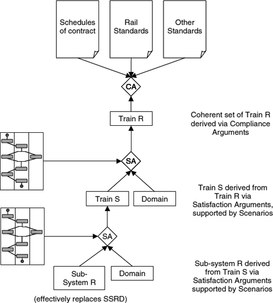
FIGURE 20.4 Compliance arguments (CA) were used to show compliance against each clause of contractual documents, resulting in a single set of train requirements. Scenarios were used to derive train specifications and domain statements from train requirements, and to explain the Satisfaction Argument (SA). Similarly, scenarios were used to derive sub-system requirements from train specifications
Each Train requirement was then analysed, Train specifications and further domain statements were written and a Satisfaction Argument was formulated. Where appropriate, scenarios were used for this analysis, and also to support the Satisfaction Argument.
Using the Separation of Concerns, each clause (or part of one) corresponded with a statement in the requirements database. Statements from more than one document could be traced to the same statement in the database. Hence, we could derive a single set of statements that complied with a large number of documentary sources. The term ‘statement’ is used deliberately, since many of the statements were specifications of the proposed solution, or contextual information (which in REVEAL is called Domain Knowledge).
How Scenarios were Used
One scenario was written for each Train requirement that was suitable for such analysis. These were essentially operational requirements, which led to linear, deterministic interactions with other entities. These included requirements for discrete events such as starting, stopping, door control, and change of Train operating mode, as well as various maintenance, depot, and emergency procedures. Each scenario was used as the basis for deriving Train specifications, and the domain knowledge required to show that the requirement was satisfied. Scenarios were also used to further analyse Train specifications, deriving sub-system requirements and additional domain knowledge. The scenario acts as the contextual glue that shows how satisfaction will be achieved. In REVEAL, a scenario consists of a set of End-to-End Conditions and an activity diagram.
In each elicitation session, a facilitator led a group of two to four client engineers in the analysis of a single Train-level requirement. This was a two-stage process that firstly involved eliciting information to complete the End-to-End Conditions using a simple tabular template. Secondly, it involved facilitating the development of an activity diagram for the scenario. The main purpose was to elicit the system specifications and domain knowledge needed to address the requirement. A useful side effect of the method was that the Satisfaction Argument was developed automatically as the activity diagram was built. This was because the activity diagram showed the relationships and dependencies between the system being developed and the entities with which it would interact. The activity diagram explained how each activity related to the preceding and subsequent activities by other participating entities.
The End-to-End Conditions include attributes such as the Stimulus that initiates the scenario, the Goal, and the Success End Conditions (the required conditions at the successful completion of the scenario). They also include any Assumptions (pre-conditions) that must hold for the scenario to occur and Possible Failure Conditions (acceptable circumstances that may prevent the scenario from reaching its intended Goal). The Frequency of occurrence and any Constraints on the scenario are recorded, and there is an optional Rationale to explain why the scenario has been written in a particular way. Together, these attributes define the scope of the scenario.

FIGURE 20.5 Scenario end-to-end conditions completed in a simple tabular template, which provides slots for useful information about the scenario and collectively defines the scope of the scenario
A set of End-to-End conditions for an example scenario is shown in Figure 20.5, and the corresponding activity diagram is described below. The scenario addresses the Train-level requirement for ‘Emergency Alarm in Automatic Mode’.
In this case, the Stimulus was not very specific, but this reflects the reality of the situation. It is not possible to predict the circumstances that will lead to a passenger operating the alarm. Indeed, it is not particularly important why the alarm was raised. For the development of the scenario, it was more important to document the desired behaviour of the Train as a result of the alarm being raised.
The Goal was more clear-cut: to stop the Train safely. However, even this needs some qualification, as it depends upon where the Train is when the alarm is raised. This point raised an important (and contentious) issue during the development of this scenario. There was disagreement among the client's engineers as to how the position of the Train would be determined. Specifically, it had not yet been decided whether the Train itself, or the Automatic Train Control (ATC) would determine the position of the Train. This was important, not only because the ATC was outside the scope of the system being built, but also because there would be significant cost implications if the Train itself had to determine its position. A domain statement was written stating that the ATC would determine the position of the Train, and an assumption was included in the End-to-End conditions.
The End-to-End Conditions template provided placeholders for recording useful information, to help contextualise the scenario. For example, note the assumption that the driver could actually stop the Train at any point in the scenario. While this was considered to be the likely reality, the scenario model was nonetheless developed to show what would happen if the driver didn't intervene, or if the driver intervened only at particular points in the scenario. Note also the Constraint that the Train must be operating under ATC. It is necessary to record this, since the scenario could only occur when this is the case.
The main part of each facilitated session consisted of developing the activity diagram, written using basic UML notation. This was recorded on a flipchart, using sticky notes for each activity, so that the model could be easily changed. In addition, one of the client's engineers documented the attributes of any specifications that were written, while another would document the domain statements. The activity diagram was then drawn in Visio, tailored with UML templates, and the statements entered into the requirements database. The development of the example activity diagram is shown in Figures 20.6 to 20.8 and is described below.
Swimlanes were used to partition the activities into those carried by each entity. Initially, a swimlane was always put on the activity diagram for the system being considered (in this case, the Train). Then a decision was made about which domain entities had a role in the scenario (though more may be added during development of the scenario). A swimlane was added to the activity diagram for each participating domain entity. These were then cross-referenced with the Rich Context Diagram. Figure 20.6 shows that the swimlanes for the example scenario are Passenger, Driver, Train, and Automatic Train Control.
To begin populating the activity diagram, the first question was always ‘What is the stimulus?’. The details of the Stimulus appeared in the scenario End-to-End conditions, in this case the Stimulus was ‘Any situation that causes a Passenger to operate the emergency alarm’. When developing the activity diagram, the Stimulus was always challenged, as the true start of a scenario is not always easy to determine. The Stimulus was shown on the activity diagram as a solid black circle. Having determined the Stimulus, we would then consider ‘What happens in response to the Stimulus?’, that is, ‘what is the first event on the activity diagram?’

FIGURE 20.6 Swimlanes and initial activities for example scenario showing a synchronisation point: the completion of the activity before the solid horizontal bar causes all the subsequent activities to begin
The first activity was carried out by the Passenger; it was ‘Operates Emergency Alarm’. A domain statement was written to give more detail about this, but on the activity diagram we included only this simple description. We would then consider the question ‘When this activity ends, what happens next?’
The activity diagram shows a synchronisation point, where two or more activities were initiated by the completion of the preceding activity. In this case, the operation of the alarm by the Passenger initiated the Train activities: Displays Audio and Visual Indication to Driver and Displays CCTV Picture. Simultaneously, the Automatic Train Control (ATC) Determines Position of the Train.
Any event in the ‘system’ (Train) swimlane was recorded on a card as a Train specification, and was subsequently entered into the requirements management database. Specifications were given attributes, such as Name, Source, Approval Status, Content, Confidence, Stability, Rationale, Guidance, Priority, and various attributes associated with Risk. For example, the Train activity Displays CCTV Picture was written as
| Name | S.Train.EmergencyAlarmCCTVDisplay |
| Source | (stakeholder name) |
| Approv Status | Not Approved |
| Content | When the Emergency Alarm has been operated, the CCTV image from the appropriate camera will be displayed in the active cab of the Train |
| Confidence | 75% |
| Stability | High |
| Rationale | Driver needs to be aware of the situation in the car in which the alarm has been operated |
| Guidance | (guidance from engineers' experience on how this might be achieved—none was given in this case) |
| Priority | High |
Statements were tagged rather than numbered, so that the Name was meaningful. Each statement was labelled R (requirement), S (specification), or D (domain) to indicate the statement type. The next part of the name was always the entity that was the subject of the statement. The rest of the Name was used to inform the reader what the statement was about.
Any event in a domain entity swimlane was recorded as a domain statement about the appropriate entity. Each domain statement was given a Name, Text, Source, (a document or an individual) and a level of Confidence. Statements with a low confidence would be checked and, when resolved, given a higher level of confidence.
For example, the ATC activity Determines Position of the Train was written as Note that in this case, the Confidence is quite low, as the statement was an assumption at the time of writing.
| Name | D.ATC.TrainPosition |
| Text | ATC will determine the position of the Train |
| Source | (stakeholder name) |
| Confidence | 50% |
Notice that even in this immature form, the activity diagram was already starting to show how the activities related to one another. This started to make explicit which activities in the domain we relied on (e.g. the scenario would not even begin if the Passenger did not operate the alarm). In this way, we facilitated the building of the story of the expected system behaviour in response to the known (or assumed) behaviour of domain entities.
Figure 20.7 shows a more advanced version of the developing activity diagram, including decision points and a re-synchronisation point. Following the ATC activity Determines Position of the Train, the ATC carried out a different activity dependent upon the answer to the question Is any part of the Train in a Station? This is called a decision point. If the answer to the question was Yes, the ATC Demands Application of Emergency Brake (which then led to a series of activities starting with an activity carried by the Train; see the complete model Figure 20.8). If the answer was No, the ATC Drives the Train.
Meanwhile, the two activities previously carried out by the Train result in certain expected behaviour by the Driver. At this point the Driver entity must react to the Train Specifications detailed in Displays Audio and Visual Indication to Driver, and Displays CCTV Picture. Here, the scenario relied on the fact that the Driver Observes Audio Visual Indication, and Observes CCTV Picture. The Driver was outside the scope of the system being built, but the system relied on his behaviour. This shows how the activity diagram helped to show causality between actions by different entities, and how it acted to support the Satisfaction Argument for the Train Requirement.
Next there was a re-synchronisation point, followed by another decision point. This time the Driver made a decision, based on the information available, whether or not to Talk to Passenger? If the answer was No, then the ATC Drives Train to Next Station. If the answer was Yes, the Driver then Requests Communication with Passenger, which in turn leads to the Train Specification Opens Communication Channel.

FIGURE 20.7 Activity diagram showing decision points and re-synchronisation point. The re-synchronisation shows that the subsequent activity cannot commence until all of the preceding activities have completed
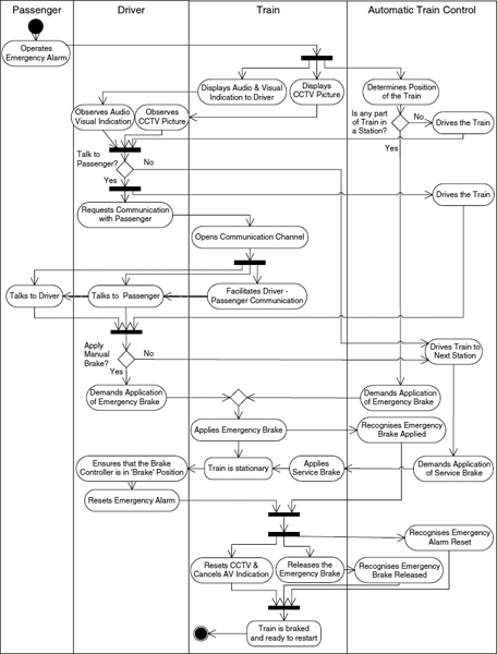
FIGURE 20.8 Complete activity diagram for ‘Emergency Alarm in Automatic Mode’. Note that ‘Train is Stationary’ and ‘Train is Braked and Ready to Start’ in the Train swimlane are not activities, but states that result from the preceding activities
Using the basic rules of UML, the rest of the activity diagram was built up in this way, as shown by the complete diagram in Figure 20.8.
The scenario (End-to-End Conditions and activity diagram) was tagged as Sc.EmergencyAlarmAuto and entered into the requirements management database. It was then linked by an Explains link to the Satisfaction Argument for the Train requirement. The Satisfaction Argument was typically output from the tool in tabular form for review, as shown in Figure 20.9.
The Rich Traceability provided by Satisfaction Arguments does far more than provide a simple link between specifications and the requirements that they address. The Contributes to links show which specifications and domain statements contribute to the satisfaction of the requirement. The Satisfaction Argument Text explains in simple terms why the specifications will satisfy the requirement, as long as the domain statements hold true. The scenario is linked to the Satisfaction Argument by an Explains link, and shows how the contributing statements combine to provide the capability expressed in the requirement.
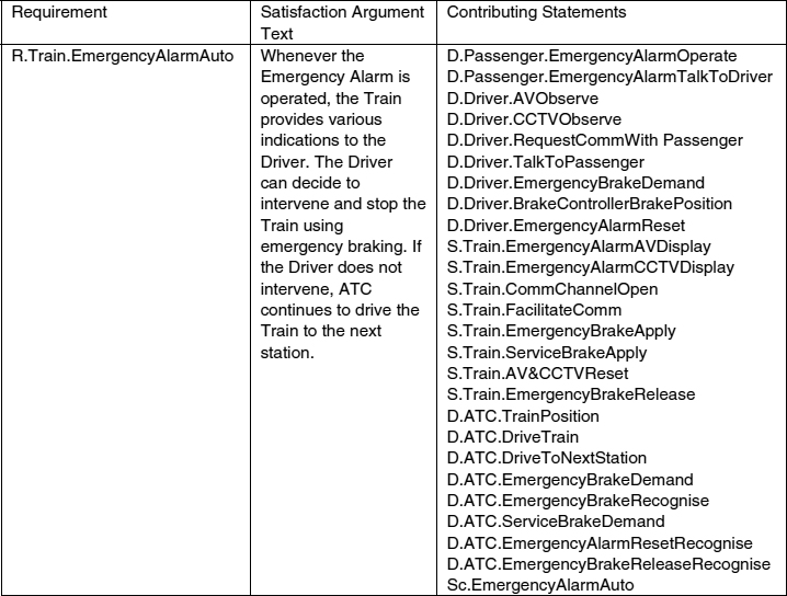
FIGURE 20.9 Satisfaction Argument (SA) for the example scenario in tabular form. The Satisfaction Argument Text gave a simple explanation of how the contributing statements were sufficient to satisfy the requirement. The Contributing Statements listed all of the statements attached to the SA by Contributes to or Explains links
A similar scenario-based approach was used to analyse Train Specifications so as to derive sub-system requirements. In this case, the activity diagram included a separate swimlane for each Train sub-system, and each activity corresponded with a requirement on that sub-system. For each sub-system supplier, the requirements on other sub-systems were effectively domain knowledge. For example, the supplier of the Brakes sub-system considered any requirements on the Traction sub-system to be Domain Statements, since these were outside the scope of the system for which they had responsibility.
Postscript to Case Study
Towards the end of our involvement in this project, we carried out some analysis of the Possible Failure Conditions for the example scenario, using a simple checklist of What if? questions. We used a list of about 25 questions based on the generic exception classes used in the RESCUE process (Mavin and Maiden 2003). The session involved walking through the scenario with a group of four stakeholders, asking appropriate What if? questions for each activity. This was always a subset of the full list of questions based on the entities involved in the activity.
The checklist included questions about activities such as ‘What if the activity does not occur?’, ‘What if the activity occurs earlier or later in time?’, and ‘What if the activity does not complete?’. It also included questions about human agents such as ‘What if the human agent makes a cognitive mistake?’, and ‘What if the human agent is physically incapable of being involved in the activity?’. There were also generic questions relating to machine agents, objects, information, communication, organisational, and environmental exceptions.
This session was quite slow getting started, but once the stakeholders were warmed up, some useful information was elicited. Initially, the walkthrough was very systematic, with all applicable exceptions considered for each activity in turn. A few additional requirements were uncovered and several issues were raised for clarification. Several activity-exception pairs were seen by the stakeholders as ‘showstoppers’ that would effectively terminate the scenario. For example, if some activities did not occur, this would result in a total break in the scenario thread.
Many more activity-exceptions pairs were considered to be quite trivial—even if the exception occurred, the scenario would continue relatively unaffected. For example, if the Train failed to display the CCTV image, the Driver would make a decision based on the audio and visual indication only, and the scenario would continue. The less clear-cut activity-exception pairs led to more discussion, and as the session progressed, the effort was concentrated on these areas.
LESSONS LEARNT
The process resulted in Train specifications that were written at the right level of granularity. When created during the development of an activity diagram, engineers wrote simple statements about each specification, offering an external or black box view of the system. In doing so, they documented what the effects of a specification should be, where previously they tended to go into the detail of the specification too early.
Suppliers of components and sub-systems had a better understanding of what the need was and how their product would be used within the system as a whole. The scenarios explicitly showed dependencies on domain assumptions, and between different sub-systems. This visibility helped sub-system suppliers to understand the environment in which their products and components would be used. In turn, this made it easier for them to demonstrate how their responses would meet the requirements placed on them.
Domain knowledge was recorded explicitly. There was only one statement of each domain assumption, which everyone used. This led to a single, common understanding of the system's context. The documentation of domain assumptions whilst writing activity diagrams enabled us to resolve issues early, and helped us reach a consensus. Where there was uncertainty about domain statements, the best guess was recorded, and assigned a low level of confidence. Unresolved issues were flagged and assigned to an issue owner, who was responsible for their resolution. This allowed progress to be made until a more concrete resolution was reached.
As a result of this process, the SSRD contained only relevant information—so it was easier for suppliers to respond. The SSRD also contained all relevant information (e.g. Domain Statements & possibly even Satisfaction Arguments)—so suppliers understood the wider picture and context of use of the products and components that they supplied. Since supplier responses were better matched to the requirements placed upon them, it was easier for the client to assess their responses.
KEYWORDS
Activity Diagram
Requirements Elicitation
System of Systems
System Context
System Specification
Domain Knowledge
Satisfaction Argument
REVEAL
Scenario
Rail
Real Time
REFERENCES
Hammond, J., Rawlings, R., and Hall, A., Will it work? Proceedings of RE01, the 5th IEEE International Symposium on Requirements Engineering, IEEE Computer Society Press, 2001, pp. 102–109.
Mavin, Alistair and Maiden, Neil, Determining socio-technical systems requirements: experiences with generating and walking through scenarios, Proceedings of RE03, the 11th IEEE International Requirements Engineering Conference, IEEE Computer Society Press, 2003, pp. 213–222.
1 REVEAL® is a registered trade mark of Praxis Critical Systems Limited.