Chapter 11: Kitbashing – Adding Details Fast
As I hope you've noticed over the course of this book, it's not just about EEVEE. It's about making renders look great and look great fast. The bulk of the workflows and tips and tricks are about EEVEE, but there's also so much value in feeling like you can use EEVEE to make something that won't require you to sit in front of your computer for months and agonize over every single detail. The idea is to give you the tools to create something amazing, not just provide rote knowledge about the technical details of EEVEE. That's why I want to give you knowledge of Geometry Nodes, alphas, the Asset Browser, and more because EEVEE can't reach its full potential without further knowledge. So, in that spirit, in this chapter, we're going to learn about kitbashing, which is a way to add more visual interest by recycling smaller pieces of geometry to give life to an otherwise boring model. This way, it's easy to build a library of parts to mix and match for each scene that you work on.
In this chapter, we'll look at kitbashing and then look at some other ways to increase the overall quality of this project, without sacrificing a lot of time. We will cover the following topics:
- Kitbashing with small objects
- Using Geometry Nodes to create sci-fi panels
Technical requirements
As usual, either download the Chapter 11-Start.blend file from the GitHub repository for the book, or take your previous Chapter 10-End.blend file and keep working on what you had. If you choose to work on the file you previously created while working through Chapter 10, Working with Irradiance Volumes and CubeMaps for Accurate Rendering, download the extra_objects.blend file and import the Details collection and SquareDetails subcollection into your file. We're going to be using these extra objects as details to add to the main objects, so make sure they're in your scene.
The supporting files for this chapter can be found here:
https://github.com/PacktPublishing/Shading-Lighting-and-Rendering-with-Blenders-EEVEE/tree/main/Chapter11
Kitbashing with small objects
When working through a scene, I often like to work from the big details down to the small. After sorting the camera composition, adding the large objects to the scene, and setting up the lighting, it's now time to add little aspects that really make the scene realistic. We've done this before in the previous mini-project where we added alphas to the environment. In this section, we're going to take small, basic objects and add them to the main objects we've already defined. Let's get to work:
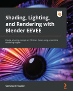
- Grab one of the detail objects to work on first. I'm going to use this one called Circle002 to demonstrate the technique.

Figure 11.1: The Circle002 detail object
- Select the object and press Tab to go into Edit Mode.
- Holding down the Alt button while in the Edge select mode, select the outermost edge of the object by right-clicking on it.
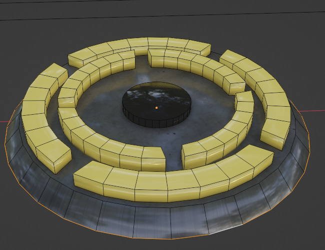
Figure 11.2: Tabbing into Edit Mode and selecting the outer edge
- Then extrude this outer edge by pressing E, then using S to scale that new edge out.

Figure 11.3: Extruding the outer edge
- Now we want to make multiple loop cuts in the new extruded face we just made. Do that by using the Ctrl + R shortcut and then using the middle mouse button to scroll up and add multiple loop cuts all in one go:

Figure 11.4: Adding loops around the extruded edge
Now we're going to add a Vertex Weight map, just like we did in Chapter 5, Setting Up an Environment with Geometry Nodes, where we used it to specify where the plants and rocks would be scattered on the landscape. For this object, we're going to use the Vertex Weight map to tell Blender how we want the object to be interpolated with others. Let's start by going to the Object Data Properties panel in the right-hand Properties panel.

Figure 11.5: The Object Data Properties panel
- Hit the plus sign to the right of the Vertex Groups section to add a new Vertex Group to this object.

Figure 11.6: Adding a Vertex Group
- Still in Edit Mode, select the entire object, and with the Weight slider set at 1, hit the Assign button in the Vertex Groups section:
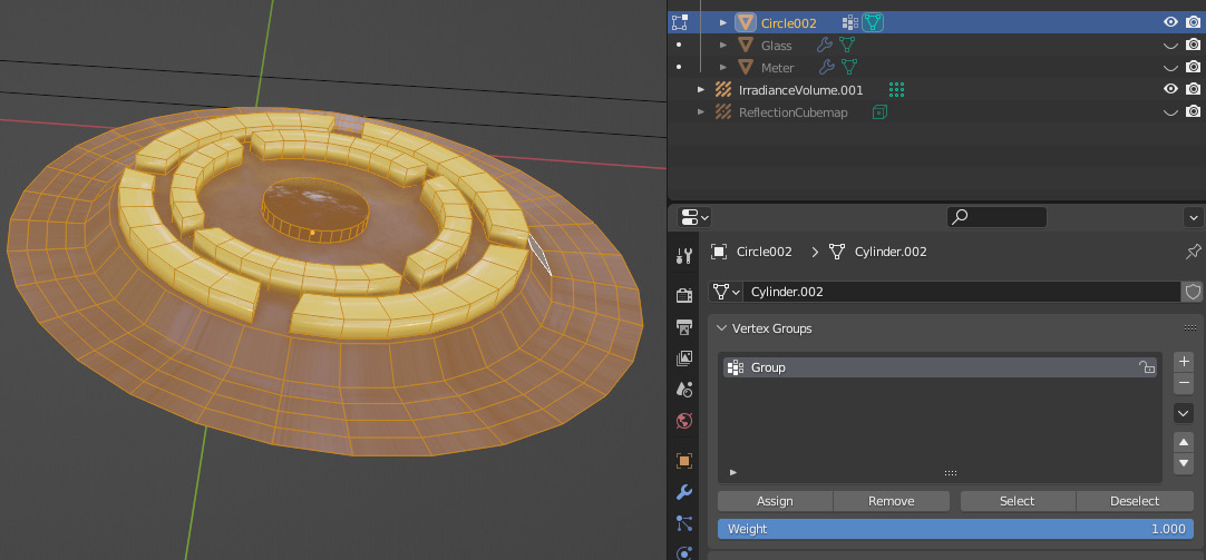
Figure 11.7: Applying a weight of 1 to the whole object
Now, when we move to Weight Paint mode, the object should be entirely red, which signifies that the whole object is set to a weight of 1. What we want is for the edges of our object to be red, but the inside of our object to be blue, with a gradient in between those two extremes. Luckily, Blender gives us a gradient tool to achieve this, so we don't have to try painting this effect by hand.

Figure 11.8: The weight map at present
- When in Weight Paint mode, we can change our painting type to Gradient by selecting it from the options in the top left corner.
Figure 11.9: Changing the Weight Paint Mode to Gradient
Then, change the Gradient type from Linear to Radial, Radial being a circular gradient, which is exactly what we need. Make sure Weight is set to 0.000 as well. We want to start painting in the center of the circle with a weight of 0, and increase the weight as we get closer to the edges of the circle.
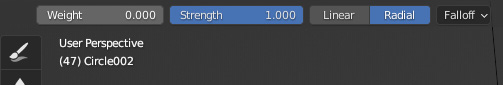
Figure 11.10: Changing the Gradient type to Radial
- Since we will be painting in the Viewport, we also want to make sure we're seeing the object from directly above when we start to paint, so everything is even. Do this by hitting 7 on the Numpad, or by going to View, then Viewport, then selecting Top.

Figure 11.11: Changing the Viewport to a top-down view
- Now we can start to paint. Click once in the very center of the circle, then drag outward until you are near the edge. You don't want to go all the way to the edge of the circle, as we still want some red at the edges.

Figure 11.12: The finished weight map
With the gradient smoothly transitioning from blue to red, it's now easy to take this Weight Paint map and use it to influence the Shrinkwrap modifier we'll add to the object. The Shrinkwrap modifier takes one object and, exactly as the name suggests, shrink-wraps it onto another object. We'll add this modifier to the Circle002 object and then tweak the outcome so we get the best possible result.
If you're still in Weight Paint mode, change back to Object mode. You should still have the Circle002 object selected. If we go to the Properties panel, and then to the Modifier Stack, we can add a Shrinkwrap modifier by clicking on the Add Modifier button and then selecting Shrinkwrap from the available options.

Figure 11.13: Adding the Shrinkwrap modifier
- Next, we want to add the Vertex Group we just created. Click on the Vertex Group box and select the Group we made from the dropdown list:

Figure 11.14: Adding the weight map to the Shrinkwrap modifier
- The next step is designating what object we want to shrinkwrap the Circle002 object to. Using the eyedropper tool next to the Target option, we can select the object in the viewport.

Figure 11.15: Adding the targeted mesh to the Shrinkwrap modifier
If you look at our object now, it looks pretty terrible... The Shrinkwrap Modifier is trying to move our geometry to the spaceship object, but it's a little too far away to look realistic.
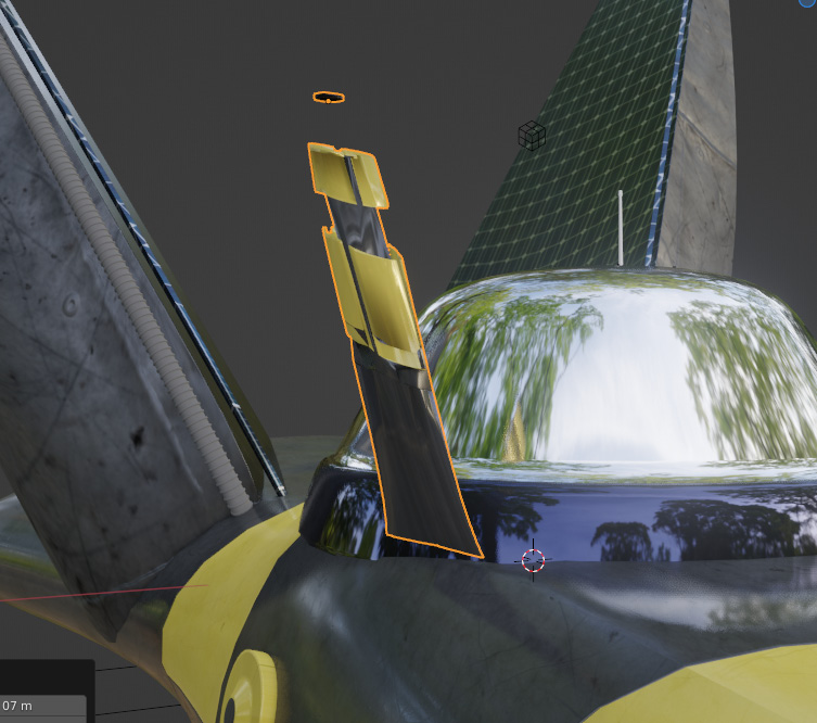
Figure 11.16: The Circle002 object stretched by the Shrinkwrap modifier
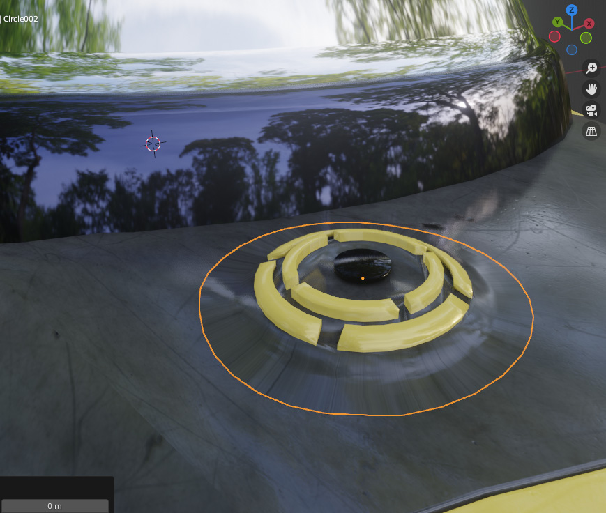
Figure 11.17: Moving the object closer to the spaceship to avoid stretching
- The Circle002 object becomes stuck to the surface of the spaceship. We can now move this detail anywhere on the surface of the mesh, rotating it to account for the orientation of the surface of the spaceship object.

Figure 11.18: Rotating the detail object to align with the position of the larger object
The overall result is a very flexible piece of geometry that we can use again and again to create lots of detail in the span of a couple of minutes.
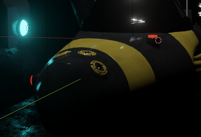
Figure 11.19: Duplicating the details and adding them to the spaceship
Copying the Circle002 object and adding it to the nose of the spaceship adds detail to a ship that might look a little simple otherwise, avoiding the pain of trying to add the details directly to our original geometry. This is also a very flexible technique – if your director doesn't like a certain detail, you don't need to remodel the spaceship or try and break pieces off of the mesh, as the details are separate from the spaceship and can be changed or deleted easily. And the beauty of mechanical parts is that they are often reused over and over again, so it makes sense to do this in our scene.
Try taking the other parts that I modeled and preparing them with the correct Vertex Maps. Then, using the Asset Browser methodology that we covered in Chapter 5, Setting Up an Environment with Geometry Nodes, mark them as assets and add them to your Blender_Assets folder that we set up to store our Asset library. Now, you can import any detail into your scene and add it to any object anywhere in no time at all. Now that we've gone through this first method, let's move on to another method for adding detail quickly using small objects. We'll be using Geometry Nodes to achieve a similar purpose as before, but for larger areas.
Using Geometry Nodes to create sci-fi panels
To finish up this chapter, we'll create a sci-fi panel to put on the blank wall to the left of the spaceship. I've taken the simple geometry that I've prepared and placed in the Square Details collection, but feel free to model some of your own. My rule of thumb for designing larger panels is that the details need to fit together, so squares are obviously the simplest shape that fit together readily into larger panels. We'll take these pieces and create a random configuration out of them so that we get the illusion of a meticulously modeled panel. So, let's move on to the instructions:

Figure 11.20: Assortment of pieces for the panel
- Let's start out by creating a Geometry Node modifier for the object and call it SciFiPanel. Select the object, go to the Modifier panel in the Properties panel and use the dropdown to add a new Geometry Nodes modifier.

Figure 11.21: Geometry Nodes modifier
- The first node we want to add is the Instance on Points node, and then check the Pick Instance option in the node's settings. This means we want the node to randomly pick one of the objects in the Square Detail collection and put it on a point, instead of putting all objects from the collection on each point.
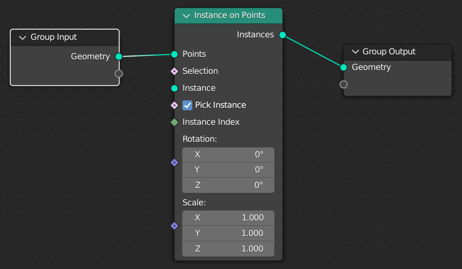
Figure 11.22: Adding an Instance on Points node
- The next node we need is one to define which collection we want to instance. Add a Collection Info node and input the SquareDetail collection into the selection box. Then check both Separate Children and Reset Children. This indicates we want each separate object to be scattered, and it clears any transforms we have on the objects in the SquareDetail collection that might cause problems.
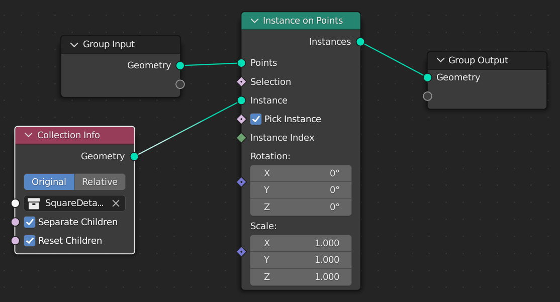
Figure 11.23: Adding the Collection Info settings
- Alright, we have now created a really interesting pattern just by combining some simple shapes in a random pattern. But this isn't really flexible at this point. We can't try different configurations. Let's fix that by adding a Random Value node:
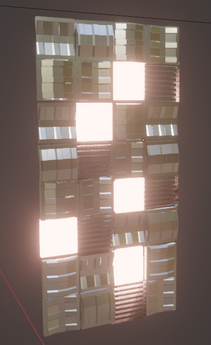
Figure 11.24: The random configuration of objects for our panel
- After adding the Random Value node, connect it to the Instance Index input on the Instance on Points node.

Figure 11.25: Adding the Random Value node
- You may notice that now we don't have a random pattern or random scattering. We just have one object being repeated across the sci-fi panel.
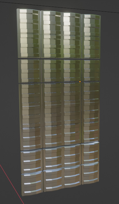
Figure 11.26: The panel with a Max value of 1.000
- This might be the result we want. But, to get our other objects back, all that is needed is to increase the Max value for the Random Value node. This way, each point in the sci-fi panel is given a random number between 0 and 5, each value standing for an object. We can then seed the different values to change our results by increasing the value in the Seed box of the Random Value node.
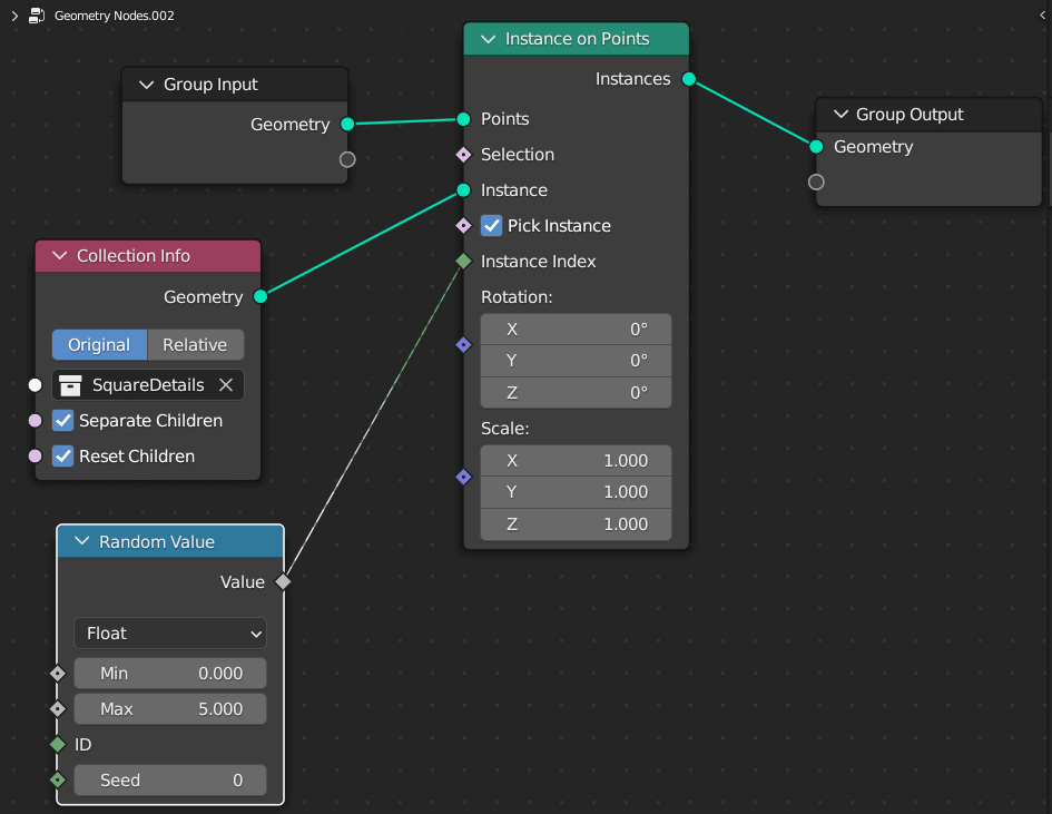
Figure 11.27: Changing the Max value to 5.000
- This results in all of our objects being randomly scattered, just like before. But now we can change the Max value in the Random Value node to tell Blender to use more or less of our objects or increase the Seed value to see different configurations.

Figure 11.28: The Random Value node

Figure 11.29: Changing the Max value to 3.000
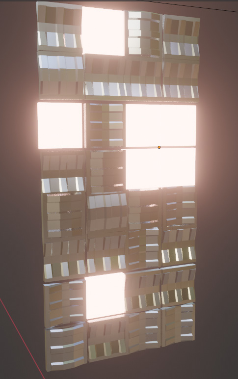
Figure 11.30: The results with a Max value of 5.000
- Try increasing the Seed value to 2 and see how the different panels change their position and randomize.

Figure 11.31: Changing the Seed value to change the configuration
And we now have a really simple, but complex-looking, sci-fi panel that we can tweak using the Geometry Nodes modifier to get the exact formation we want.
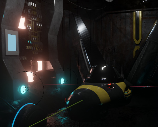
Figure 11.32: The panel in the scene
In this section, we worked through another application of Geometry Nodes, this time to create a machine panel incorporating some randomization but constraining the scattering to a more ordered grid formation. You can now see how truly amazing Geometry Nodes are, and should feel compelled to further your knowledge so you can create even more complicated procedural structures in Blender.
Summary
In this chapter, we took two different approaches to add small details to the spaceship and its hangar to make the scene look much more detailed and effective than what we would get by modeling and placing every single detail manually. First, we created small details that can be applied to different sections of the spaceship with a Shrinkwrap modifier. The other technique involved using Geometry Nodes to create a grid-based patterned panel that we can randomize at will. The scene I ended up with looks like this:
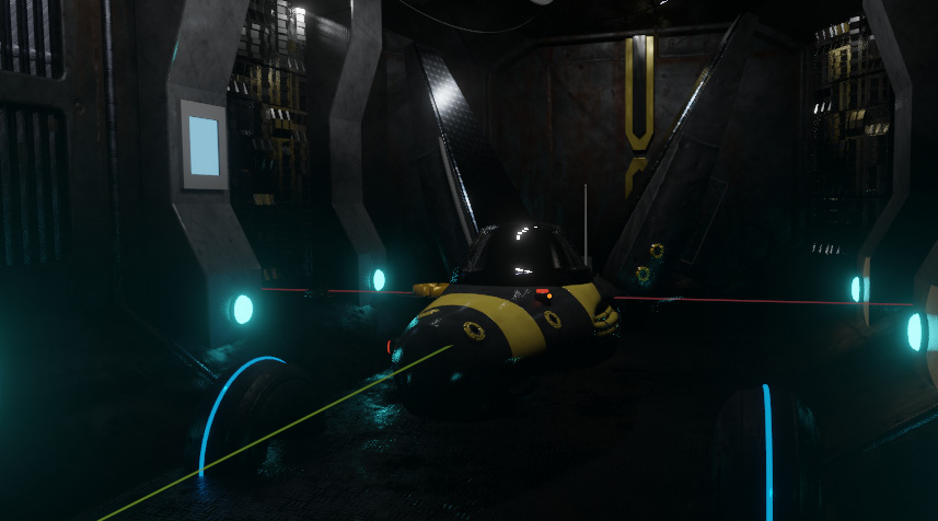
Figure 11.33: The sci-fi panels on the walls, with details added to the spaceship
Of course, you can spend as much or as little time as you want on adding more details, modeling your own additions to the scene, and taking it as far as you want to. Adding signs or pieces of text could be really cool for this scene, and you could also consider adding more complicated pieces of detail to the sci-fi panel. I just wanted to show you what is possible and give you the tools to take it further and make your artwork better, faster.
After working through this chapter, you should understand the importance of using small mechanical-style objects and being able to duplicate and scatter them for a really intricate visual effect. The next chapter is one of the most fun chapters in this book: How to create fire with EEVEE!