Chapter 11
Preparing Models for Presentation
IN THIS CHAPTER
![]() Walking around inside your model
Walking around inside your model
![]() Creating scenes to capture particular views
Creating scenes to capture particular views
![]() Making animations with scenes
Making animations with scenes
![]() Cutting slices through your model with section planes
Cutting slices through your model with section planes
![]() Generating plans and sections
Generating plans and sections
After you make a model, you probably want to show it to someone. How you present your work depends on the idea you want to convey. The tricky part about using SketchUp to present a model isn’t actually using the tools; it’s choosing the right tools to get your idea across without a bunch of extra information distracting your audience. Most 3D models have so much to look at that the real challenge is finding a presentation method that helps you focus on the stuff you want to talk about.
In this chapter, you learn about three ways to show off your models without ever leaving SketchUp. If you’ve made a building, you can walk around inside it. You can even walk up and down stairs and ramps — just like in a video game. You can create animated slide shows by setting up scenes with different camera views, times of day, and even visual styles. If you want to talk about what’s inside your model, you can cut sections through it without taking it apart. Even — and especially — if you need to present your model in 2D, you still need to compose the views of your model as Scenes in SketchUp.
As you read this chapter, think about what you want your model to communicate. As with everything else in SketchUp (and in life, we suppose), a little bit of planning goes a long way. Whether you are developing a set of printed plans or presenting a model live in SketchUp, you can’t really go wrong, so have fun.
Exploring Your Creation on Foot
Few experiences in virtual life are as satisfying as running around inside your model. After you make a space, you can walk around it, go up and down stairs, bump into walls, and even fall off ledges. You can check to make sure that the television is visible from the kitchen, say, or experience what it’d be like to wander down the hall. In a potentially confusing building, such as an airport or a train station, you can figure out where to put the signs by allowing someone who’s never seen your model to explore the space “on foot.” The following sections, uh, walk you through how to use these features.
These tools were made for walking
A couple of tools in SketchUp are dedicated to moving around your model as if you were actually inside it. The first step (no pun intended) is to position yourself so that you seem to stand inside your model. This can be tricky with just the Orbit, Pan, and Zoom tools, so SketchUp provides a tool just for this: Position Camera. After you’re standing in the right spot (and at the right height), you use the Walk tool to move around. It’s as simple as that.

![]() In SketchUp for Web, there is no Camera menu, but most of the camera tools in this chapter are available in the bottom of the tool tray on the left. They’re nested underneath the Walk tool (the footprints icon).
In SketchUp for Web, there is no Camera menu, but most of the camera tools in this chapter are available in the bottom of the tool tray on the left. They’re nested underneath the Walk tool (the footprints icon).
Standing in the right spot: The Position Camera tool
The Position Camera tool precisely places your viewpoint in SketchUp in a particular spot. That’s really all it does, but it works in two ways.
 An easy way to set a suitable camera position is to switch to a plan view. Choose Camera ⇒ Standard Views ⇒ Top. (Web: Use Search to find this view.)
-
You want to stand right here. Choose Camera ⇒ Position or click the Position Camera tool. (You find it on the Large Tool Set in both Windows and Mac.) Then click anywhere in the modeling window to automatically position your viewpoint 5 feet, 6 inches above wherever you clicked. Because this is the average eye height of an adult, the result is that you are, for all intents and purposes, standing on the spot where you clicked, and are facing the same direction that you were before you clicked; see Figure 11-1. After you use the Position Camera tool, SketchUp automatically switches to the Look Around tool, assuming that you may want to look around. We talk about Look Around in the “Stopping to look around” section of this chapter.
To get a feel for this, start a new file. Create a few random circles and rectangles, and push/pull them to different heights. Now set the camera position at the toe of the scale figure. Your view changes. Now hold the left mouse button down and move your mouse. As you move it up/down and left/right you soon realize that you’re looking through the eyes of the scale figure.
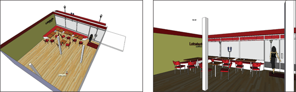
FIGURE 11-1: Drop yourself into your model with the Position Camera tool.
 You’re not stuck being 5'6" tall forever. After you launch the Position Camera tool, but before you pick a location, type the height you’d rather be and press Enter. Your new eye height appears in the Measurement box. Type 1" to see a mouse’s view of the world, or type 17' to pretend you’re a giraffe. This height offset is remembered within the current editing session, even if you switch to other files, but resets to 5'6" when you close and restart SketchUp.
 -
You want your eyes to be right here, and you want to look in this direction. Select the Position Camera tool, click and hold down the mouse button while in the spot where you want your eyes to be, drag over to the thing you want to look at (you see a dashed line connecting the two points), and release the mouse button; see Figure 11-2. We call this the direct view technique.
Try the direct view technique a couple times; it takes a bit of practice to master. Use Position Camera in this way if you want to stand in a particular spot and look in a particular direction. This technique works great with scenes, covered later in this chapter.
 With the direct view technique, your height offset is set to zero, and if you then add an offset value it changes both the camera location and the target point. To see what the scale figure sees using direct view, you need to select their eyes, not their toes, for the first point.

FIGURE 11-2: Click and drag with Position Camera to aim your view.
Stepping out with the Walk tool
![]() After you use the Position Camera tool to place yourself in your model, use the Walk tool to move through it. You find the Walk tool on the Camera menu or the Large Tool Set; it’s the pair of footprints.
After you use the Position Camera tool to place yourself in your model, use the Walk tool to move through it. You find the Walk tool on the Camera menu or the Large Tool Set; it’s the pair of footprints.
To walk around, click and drag the mouse in the direction you want to move:
- Straight up is forward.
- Straight down is backward.
- Anything to the left or right causes you to turn while you walk.
The farther you move your cursor, the faster you walk. Release the mouse button to stop. If you’ve ever played video games, you’ll get used to it quickly. If Scrabble is more your speed, it’ll take a few minutes to get the hang of things.
Moving the Walk cursor controls speed and direction, not location. Once you’re walking, you don’t need to move the cursor more to get to a distant location if you aren’t in a hurry.
You can even use the Walk tool to walk up and down stairs and ramps. Keep in mind that the highest step you can climb is 22 inches; anything higher creates the “bump” cursor, just like you walked into a wall. Also, if you walk off a high surface, you fall to the surface below. Similarly, if you suddenly can’t move any farther, perhaps you collided with something you can’t see such as a coffee table. (At times like these, we wish SketchUp had cartoon sound effects.)
Using modifier keys in combination with the Walk tool makes SketchUp even more like a video game:
- To run instead of walk, hold down the Ctrl key (Mac: Option) while you’re using the Walk tool with your mouse. This may be useful if you’re trying to simulate what it’d be like if a werewolf were chasing you through your model.
- To make the Walk tool change your eye height or move sideways, use the Shift key. To move straight up like you’re growing, hold down the Shift key while you move your mouse up. To get shorter, hold down Shift and move your mouse down. To move sideways like a crab, hold down Shift and move your mouse left or right.
- To disable collision detection so that you can walk through walls, hold down the Alt key (Mac: Command). Burglars find this handy for entering models without breaking any windows.
Stopping to look around
![]() Look Around is the third tool in SketchUp that’s dedicated to exploring your model from the inside. If using Position Camera is like swooping in to stand in a particular spot and Walk is like moving around while maintaining a constant eye height, Look Around is like turning your head while standing in one spot. It’s pretty well named, we think; it does exactly what it says.
Look Around is the third tool in SketchUp that’s dedicated to exploring your model from the inside. If using Position Camera is like swooping in to stand in a particular spot and Walk is like moving around while maintaining a constant eye height, Look Around is like turning your head while standing in one spot. It’s pretty well named, we think; it does exactly what it says.
Using Look Around is so simple it hardly merits these steps:
- Choose Camera ⇒ Look Around.
-
Click and drag around in the modeling window to turn your virtual head.
Don’t move too fast, or you’ll strain your virtual neck.
Be sure to only click and drag. If you use the Zoom, Pan (H), or Orbit tools while looking around, it can mess up your view something fierce.
When you’re using any of the navigation tools, right-click to access any other navigation tool; this makes switching between them a little easier.
When you use the Look Around tool with the Field of View tool discussed in the next section, you get a pretty darned realistic simulation of what it’d be like to stand in your model.
Setting your field of view
Field of view is how much of your model you can see in your modeling window at one time. Imagine your eyesight kind of like a cone, with the pointy end pointing at your eyes and the cone getting bigger as it gets farther away from you. Everything that falls inside the cone is visible to you, and everything outside the cone isn’t.
If you increase the angle of the cone at the pointy end, the cone gets wider, and you see more of what’s in front of you. If you decrease the angle, the cone gets narrower, and you see less; see Figure 11-3.

FIGURE 11-3: The wider your field of view, the more you can see.
You can only change the field of view when in Perspective view mode, but the setting will be remembered if you then switch to Parallel view mode.
Measured in degrees, a wide field of view means that you can see more of your model without having to move around. The bigger the angle, the more you can see. A wide field of view comes in handy when you’re inside a SketchUp model because working on a model you can’t see is hard.
It’s a good idea to fiddle with your field of view before walking around inside your model. Follow these steps to do so:
-
Choose Camera ⇒ Field of View (Web: Search for FOV).
Notice that the Measurements box in the lower-right corner of your modeling window says Field of View and that the default value is 35 degrees. This means that you currently have a 35-degree cone of vision, which is kind of narrow.
-
Type 60 and press Enter.
Your field of view increases, and you now have a wider view of your model. The trade-off is that you see more distortion at the edges of your modeling window as more information is displayed in the same amount of space.
A good guideline for setting your field of view is to strike a balance between quantity and quality; a wider view always means more distortion. For views of the outside of something, try a field of view of 35 to 45 degrees. For interior views, you can increase the field of view to 60 or 70 degrees.
 If you know something about photography, you can express field of view in millimeters, just like you’re using a camera lens. Typing 28mm gives you a wide-angle view, as if you’re looking through a 28mm lens versus a 50mm (standard) or 150mm (telephoto) lens. For people who think about field of view in these terms, this option can be a lot more intuitive than trying to imagine cones of vision.
Taking the Scenic Route
Wouldn’t it be great if you could save a particular view of your model? And wouldn’t it be even greater if that view could also save things like styles and shadow settings? What if you could come back to any of these saved views by clicking a button on your screen? What if this whole paragraph were just a series of questions? What if there were no rhetorical questions?
SketchUp scenes are (you guessed it) saved views of your model, except that scenes can save much more than just camera positions.
Although scenes don’t get a lot of space in this book (they don’t even get their own chapter), scenes are an incredibly important feature in SketchUp for several reasons:
- Scenes can save you hours of time. Returning to exactly the right view with Orbit, Zoom, and Pan isn’t always easy. Sometimes a view involves shadows, styles, sections (you read about those later in this chapter in “Mastering the Sectional Approach”), and even hidden groups and components. Setting up everything the way you need it, every time you need it, can be a pain. It’s not that SketchUp’s hard; it’s just that you have a lot of different ways to view your model. Making a scene enables you to apply dozens of settings with a click of your mouse.
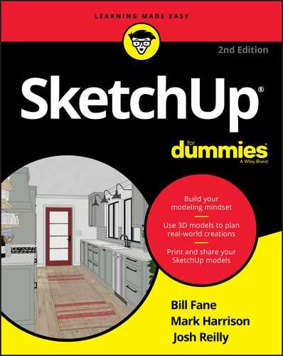
- Scenes are by far the most effective way to present your model. Saving a scene for each point that you want to make in a presentation allows you to focus on what you’re trying to say. Instead of fumbling around with the navigation tools, turning on shadows, and making the roof visible, you can click a button to transition to the next scene (which you’ve already set up exactly the way you want). Figure 11-4 shows a set of scenes that were created to present a house designed for a dog.
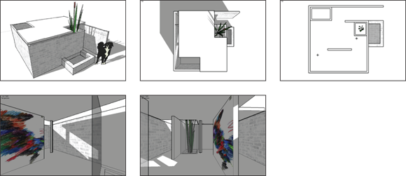
FIGURE 11-4: To show very specific views, create scenes.
- Scenes are the key to making animations. You make animations by creating a series of scenes and telling SketchUp to figure out the transitions between them. The process, explained in later sections, is as simple as clicking a button.
- Scenes help you compare design scenarios. One of the most important things that scenes remember is which groups and components are visible and which ones are hidden. So, if you want to compare the layout of a room with one set of furniture versus another, simply hide one furniture group and create a scene. Then unhide it, hide the other, and create a different scene.
After you get used to scenes, you’ll find yourself using them all the time. Here are some of the most common uses for scenes:
- Showing shade conditions for the same area at different times of the day. See Chapter 10 for details about shadow studies.
- Saving scenes for each floor plan, building section, and other important views of your model.
- Building a walkthrough or flyover animation of your design.
- Creating scenes that show several views of the same thing with different options (the pointy roof or the flat one, madam?).
- Demonstrating change over time by showing or hiding a succession of components. Chapter 5 is all about components.
Creating scenes
Before you start making a scene, know this: Making a scene in SketchUp is not like taking a snapshot of your model; neither is it like an unruly child in a supermarket. If you create a scene to save a view, continue working on your model, and then return to that scene, your model doesn’t go back to the way it was when you created the scene. The camera position will be the same, and the settings will be the same, but your geometry will show the revised configuration. This is a pretty important concept, and one that makes using scenes so powerful.
A scene is just a set of view settings, which means that they’re automatically updated every time you edit your model. You can make some scenes and use them all the way through your process, from when you start modeling to when you present your design to the president. Or to your mother.
Creating scenes is a simple process. The basic idea is that you add a scene to your SketchUp file whenever you have a view you want to return to later. You can always delete scenes, so there’s no downside to using lots of them. Follow these steps to make a new scene:
-
Open the Scenes panel.
(Web: Manage scenes in the View panel using the movie clapboard icon on the right toolbar. You can also search for Add Scene.)
When the Scenes panel first opens, it doesn’t look like there’s much to it. Expanding it by clicking the Show Details button in the upper-right corner reveals more options, but don’t worry about that right now. (Web: The scene details are available by clicking the little arrow that appears when you mouse over a scene name.)
-
Set up your view however you want.
Navigate around until you’re happy with your point of view. If you want, use the Shadows and Styles panels to change the way your model looks.
-
Click the Add Scene button to make a new scene with your current view settings.
A new scene is added to your SketchUp file. If this is the first scene you’ve created, it’s called Scene 1, but you can give it a more meaningful name, as explained later in this chapter. As shown in Figure 11-5, the scene appears in two places:
- As a tab at the top of your modeling window (Desktop only)
- As an item in the Scenes panel, right below the Add Scene button
When you’re creating a scene that shows an eye-level view of a building — whether it’s an interior or an exterior view — there’s a quick, easy step you can take to make the scene look 500 percent better: Choose Camera ⇒ Two-Point Perspective (Web: Two-Point Perspective is available in the Scenes panel) to make all the vertical edges in your model appear vertical in the view. Doing so removes the unprofessional, distorted effect that’s the hallmark of improperly wielded 3D modeling software.
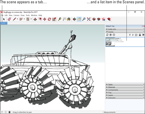
FIGURE 11-5: A scene appears in two places.
Nothing is generated outside SketchUp when you add a scene; it’s not like exporting a JPEG or a TIFF. Scenes are just little bits of programming code that “remember” the view settings in effect when you create the scene. Scenes also don’t add much to your file size, so you don’t have to worry about using too many of them.
Moving from scene to scene
Activate a scene you’ve added earlier by doing one of three things:
- Double-click the name (or thumbnail image) of the scene in the Scenes panel. (Web: Just one click will do.)
- Click the tab for that scene at the top of the modeling window (Desktop only).
- Right-click any scene tab and choose Play Animation to make SketchUp automatically flip through your scenes. Choose Play Animation again to make the animation stop. (Web: Use the Play icon in the Scenes panel.)
Notice how the transition from one scene to the next is animated? You don’t have to do anything special to make this happen; it’s something SketchUp automatically does to make things look better (and ultimately, to make you look better).
You can adjust the way SketchUp transitions between scenes, which is handy for customizing your presentations. Follow these steps to access these settings:
-
Choose Window ⇒ Model Info.
You can also select View ⇒ Animation ⇒ Settings. (Web: Animation settings are in the Scenes tab.)
-
On the left side of the Model Info dialog box, choose Animation.
The Animation settings panel in the Model Info dialog box isn’t very complicated, but it can make a huge difference in the appearance of your scene-related presentations.
-
In the Scene Transitions area, set how SketchUp transitions from one scene to another.
These settings apply to both manual (clicking a page tab) and automatic (playing an animation) scene transitions:
- Enable Scene Transitions: Clear this check box to make SketchUp change scenes without animating the transitions between them. You probably want to do this if your model is so complex (or your computer is so slow) that animated transitions don’t look good.
- Seconds: If you’ve selected the Enable Scene Transitions check box, the number of seconds you enter here indicates the time SketchUp takes to transition from one scene to the next. If you’re “moving the camera” very far between scenes, bump up the transition time so that your audience doesn’t get sick. Three seconds is a good compromise between nausea and boredom.
If you’re presenting an incomplete model (perhaps you’ve thought about the garage and the living room, but nothing in between), it can be helpful to turn off scene transitions. That way, your audience won’t see the things you haven’t worked on when you click a tab to change scenes. It’s sneaky, but effective. -
In the Scene Delay area, set the length of time SketchUp pauses on each scene before it moves to the next one.
If you want the presentation to seem like you’re walking or flying, set this to 0. If you want time to talk about each scene in your presentation, bump this setting up a few seconds.
Modifying scenes after you make ’em
After you create a whole bunch of scenes, you inevitably need to fiddle with them in some way. After all, modifying something is almost always easier than making it all over again, and the same thing holds true for scenes. Because your SketchUp model will change a million times, understanding how to make changes to your existing scenes can save you a lot of time in the long run.
Certain aspects of the scene-modification process can get a little tricky. This is kind of surprising, given how simple the rest of working with scenes can be. You deal with a lot of complexity when working in SketchUp, and this is just one of the places where that complexity rears its ugly head. The upshot: Pay special attention to the section on updating scenes and don’t worry if you take a little while to figure things out. It happens to the best of us.
Reordering, renaming, and removing scenes
Making simple modifications to scenes, such as reordering, renaming, and removing them, is easy. You can accomplish each of these in two ways: You either right-click a scene tab at the top of your modeling window or use the Scenes panel menu (click the menu arrow in the upper right); see Figure 11-6.
Here’s how to reorder, rename, or remove scenes:
- Reordering scenes: You can change the order in which scenes play in an animation. If you’re using scenes, you need to do this often — trust us. Use one of the following methods:
- Right-click the tab of the scene you want to move (in the modeling window) and choose Move Right or Move Left.
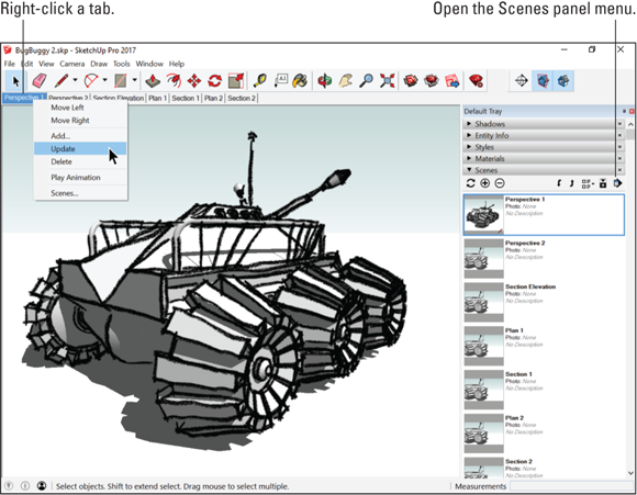
FIGURE 11-6: You can modify scenes by right-clicking scene tabs or by using the Scenes panel.
- In the expanded Scenes panel, click the name (or thumbnail image) of the scene you want to move to select it. Then click the Move Scene Up or Move Scene Down arrow at the top of the panel to change the scene’s position in the scene order.
- Web: Click and drag in the Scenes panel.
- Right-click the tab of the scene you want to move (in the modeling window) and choose Move Right or Move Left.
-
Renaming scenes: Give your scenes meaningful names: Living Room, Top View, and Shadows at 5 p.m. are descriptive enough to be useful. Scene 14 lacks a certain je ne sais quoi. Use one of the following methods:
- Right-click the scene tab and choose Rename.
 In the Scenes panel, select the scene you want to rename and type something into the Name field below the list. If you don’t see the Name field, click the Show Details button in the upper right. If you’re feeling really organized, go ahead and give the scene a description too; more information never hurts.
- Web: Select and type in the Scenes panel.
-
Removing scenes: If you don’t need a scene anymore, feel free to delete it. However, if you have a scene that you don’t want to appear in animations, you don’t have to get rid of it. Use one of the following methods to remove a scene:
- Right-click the scene tab and choose Delete to get rid of it permanently.
- In the Scenes panel, select the scene you want to ax and click the Delete button.
- Web: Select in the Scenes panel and then click the trash-can icon.
To exclude a scene from animations without getting rid of it, select its name (or thumbnail) and clear the Include in Animation check box.
Working with scene properties
Okay. Turn off the television. Send the kids outside to play. Do whatever you need to do to concentrate because wrapping your head around the concept of scene properties isn’t altogether straightforward. We do our best to explain it.
Basically, a scene is just a collection of saved viewing properties. Each of these properties has something to do with how your model looks:
- Camera Location: Camera Location properties include the camera position, or viewpoint, and the field of view (discussed earlier in this chapter).
- Hidden Objects: Objects are groups and components. This means each scene can remember which groups or components are hidden and which are visible. This is probably the easiest way to use scenes to control visibility.
- Hidden Geometry: Hidden Geometry includes the individual edges and faces (within groups and components) which you may have designated as hidden.
- Visible Tags: Visible Tag properties keep track of the visibility of tags in your model. Using tags to control visibility takes a few more clicks than simply hiding individual groups and components — check out Chapter 7 — but for a while this was the primary way to control visibility with scenes. And it’s still a good tactic if you’ve been aggressively organizing your model with tags.
- Active Section Planes: Active Section Plane properties include the visibility of section planes and whether they’re active. We talk about sections in the last part of this chapter.
- Style and Fog: Style and Fog properties are all the settings in the Styles and Fog panels, and there are a lot of them. (See Chapter 10.)
- Shadow Settings: Shadow Settings properties include whether shadows are turned on and the time and date for which the shadows are set. They also include all the other settings in the Shadows panel.
- Axes Location: Axes Location properties are very specific. They keep track of the visibility, location, and orientation of the main red, green, and blue axes in your modeling window. It’s sometimes useful to move the axes around when you’re working, such as when you’re working with a rotated street grid in an urban-scale model.
Here’s the tricky part: Scenes can save (remember) any combination of the preceding properties — it’s not an all-or-nothing proposition. After the full impact of this information soaks in, you’ll realize that this means that scenes are much more powerful than they first appear.
By creating scenes that save only one or two properties (instead of all seven), you can use scenes to do some pretty nifty things. Here are three of our favorites:
- Create scenes that affect only your camera location, allowing you to return to any point of view without affecting anything else about the way your model looks (such as styles and hidden geometry).
- Create scenes that affect only styles and shadows, letting you quickly change between simple and complex (hard on your computer) display settings without affecting your camera location.
- Create scenes that have different combinations of Hidden Objects to look at design alternatives without changing your model’s style and camera location.
The key to working with scene properties is the expanded Scenes panel, visible in Figure 11-7. (Web: These properties are available by clicking the arrow that appears when you mouse over a scene name.) Although this panel is pretty simple, folks who understand it are few and far between. Prepare to join the informed minority.
Follow these steps to set which properties a scene saves:
-
In the Scenes panel, select the scene whose properties you want to fiddle with.
You don’t have to view this scene when you edit it; you can edit properties for any scene at any time.
- If not already expanded, click the Show Details button in the upper-right corner of the Scenes panel.

FIGURE 11-7: Choose which scene properties to save in the expanded Scenes panel.
-
Select the check boxes next to the properties you want to save.
That’s it. You don’t have to click Save to make your changes stick. A little anticlimactic, no?
One terrific use of scene properties is to create scenes that help you show off different iterations (versions) of your design. You do this by using Tags or Outliner to turn off and on the visibility of individual groups and components, and then creating a scene to capture that iteration.
Updating scenes
If you want to update (make changes to) an existing scene, you have a couple options:
- Update all the scene’s properties at once, which is a piece of cake.
- Update the scene’s properties selectively, which isn’t quite as simple. Read on for both sets of instructions.
After you update a scene, you can’t use Undo to return the scene to the way it was. Instead, save your SketchUp file right before you update a scene and choose File ⇒ Revert if you don’t like the results. (Web: There’s revision history on your SketchUp file, so you can always access a copy of your file from a few minutes ago in the Home tab.) For more information on accessing previous versions. see “SketchUp Crashed, and You Lost Your Model” in Chapter 14.
UPDATING ALL THE SCENE PROPERTIES AT ONCE
The simplest way to modify a scene is to not worry about individual properties. If all you want to do is update a scene after you make an adjustment to the appearance of your model, you’re in luck. Follow these steps:
-
Click the tab of the scene you want to update.
The tabs are at the top of the modeling window.
(Web: Select the scene and then click the update icon/button at the bottom of the tab.)
- Make whatever styles, shadows, camera, or other display changes you want to your model.
-
Right-click the current scene tab and choose Update.
Be careful not to accidentally double-click the tab, or you’ll reactivate the scene and lose all the changes you made. However, after you update the scene, the new scene properties replace the old ones, and you’re home free.
UPDATING SCENE PROPERTIES SELECTIVELY
Here’s where things get complicated. At times in your SketchUp life, you’ll want to update a scene without updating all its properties.
When you update scenes selectively, you make changes that you can’t see immediately, which means disaster might strike. Save As your SketchUp file to a different name, such as adding –1 to the end of it, before you update more than one scene at a time for when something awful happens.
Maybe you’ve used scenes to create a tour of the sunroom you’re designing for a client, and you want to change the shadow settings to make your model look brighter. You have 30 scenes in your presentation, and your meeting’s in 5 minutes. You don’t have time to change and update all 30 scenes one at a time. What to do? In the desktop version, you can follow these steps:
-
Adjust the Shadow properties to where you want them to be for all the scenes you want to update.
Although this example deals with shadows, this same method applies to any scene properties changes you want to make.
-
In the Scenes panel, select all the scenes you want to update.
Hold down the Shift key to select a group of consecutive scenes. Hold down Ctrl (Mac: ⌘ ) to select noncontiguous scenes.
-
 Click the Update Scenes button in the Scenes panel.
The Scene Update dialog box appears, as shown in Figure 11-8.

FIGURE 11-8: When you click the Update button in the upper left of the Scenes panel, you can choose which scene properties to update (or not).
-
Select the Shadow Settings check box and click the Update button.
If all you want to update are the Shadow Settings, make sure that only that check box is selected. More generally, you’d select the check box next to each of the properties you want to update. All the selected scenes are updated with those new properties, and all the properties whose check boxes are clear remain unchanged.
Mastering the Sectional Approach
Software like SketchUp has a funny way of providing moments of perfect simplicity, moments when you sit back, scratch your head, and think “That’s it? That’s all there is to it?”
Sections in SketchUp offer one of those moments. To put it simply, sections are objects that cut away parts of your model so you can look inside. However, the sections don’t actually split or otherwise alter a model’s geometry. A section is temporary and easily hidden or removed, so that you can see your whole model again just as easily as you created the cutaway.
You place sections wherever you need them, use them to create views you couldn’t otherwise get, and then delete them when you’re done. When you move a section plane, you get instant feedback; the cut view of your model moves, too. If you want to get fancy, you can embed sections in scenes and even use sections in animations. Sections are the icing on the SketchUp cake: easy to use, incredibly important, and impressive as all get-out.
People use sections for all kinds of things:
- Creating standard orthographic views (such as plans and sections) of buildings and other objects
- Making cutaway views of complex models to make them easier to understand
- Working on the interiors of buildings without moving or hiding geometry
- Generating sectional animations with scenes
Cutting plans and sections
The most common use for sections is to create straight-on, cut-through views of your model. These views often include dimensions and are typical of the drawings that architects make to design and explain a space.
Straight-on, cut-through views are useful for the following reasons:
- They’re easy to read.
- You can take measurements from them (if they’re set to a scale).
- They provide information that no other drawing type can.
The following terms (illustrated in Figure 11-9) can help you create different views of your model more easily:
- Plan: A planimetric view, or plan, is a top-down, two-dimensional, nonperspective view of an object or space. Put simply, a planimetric view is every drawing of a house floor plan you’ve ever seen. You generate a plan by cutting an imaginary horizontal slice through your model. Everything below the slice is visible, and everything above it isn’t.
- Section: Not to be confused with Sections (the SketchUp feature), a sectional view, or section, is a from-the-side, 2D, nonperspective view of an object or space. You make a sectional view by cutting an imaginary vertical slice through your model. Just like in a plan view, everything on one side of the slice is visible, and everything on the other side is hidden.
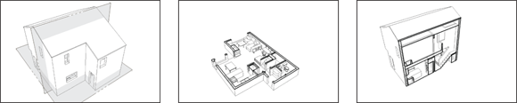
FIGURE 11-9: A plan is a horizontal cut, whereas a section is a vertical one.
You cut plans and sections by adding section planes to your model. These are a little abstract because nothing like them exists in real life. In SketchUp, section planes are objects that affect the visibility of certain parts of your model. When a section plane is active, everything in front of it is visible and everything behind is hidden. Everywhere a section plane cuts your model, a slightly thicker section cut line appears.
Open the Section toolbar by choosing View ⇒ Toolbars ⇒ Section. (Mac: The Section Plane tool is in the Large Tool Set, which you can activate by choosing View ⇒ Tool Palettes ⇒ Large Tool Set; Web: Find it nested under Tape Measure, or by searching.)
The following steps explain how to create a section plane:
-
Choose Tools ⇒ Section Plane to activate the Section Plane tool.
 You can also activate Section Plane by choosing its icon from the Large Tool Set (or if you prefer, the Section toolbar on SketchUp for Windows).
 -
Move the Section Plane tool around your model.
Notice how the orientation of the Section Plane cursor (which is quite large) changes to be coplanar to whatever surface you hover over.
-
After you figure out where you want to cut, click once to add a section plane.
To create a plan view, add a horizontal section plane by clicking a horizontal plane like a floor. For a sectional view, add a vertical section plane by clicking a wall or other vertical surface. You can, of course, add section planes wherever you want; they don’t have to be aligned to horizontal or vertical planes. Figure 11-10 shows a section plane being added to a model of a house.
In the desktop version, as soon as you place a section plane, you’ll be prompted to give it a name. We think it's a good idea, since a name makes it easier to find your scene in Outliner. You can also assign a symbol to display with your section plane.
 Choose the Move tool.
-
Move the section plane you just added by clicking it once to pick it up and again to drop it.
You can slide your section plane back and forth in only two directions so that the section plane remains perpendicular to its cutting plane. When you’re deciding where to locate your cut, the nearby sidebar “Cutting like an architect” offers helpful pointers.
After you add a section plane and move it to the desired location, you can rotate and even copy it, just like any other object in your model. The section plane never affects your geometry — just the way you view it.
Chapter 9 covers 3D printing and explains how a 3D print is built up by repeatedly printing a cross-section, moving the cutting plane, printing again, and so on. If you move a cutting plane in tiny increments then the heavy model lines like the ones in Figure 11-12 show what a 3D printer would print at each cutting-plane location. -
 If you need to rotate your section plane, select it and use the Rotate tool.
Why rotate a section plane? In certain circumstances, rotating a section plane (instead of creating a brand-new one) can help explain a complex interior space. Showing a plan view becoming a sectional one is a powerful way to explain architectural drawings to an audience that doesn’t understand them.
Read more about the Rotate tool in Chapter 3.
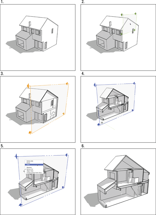
FIGURE 11-10: Add a section plane wherever you want one and then move it into position.
-
To make a new section plane by copying an existing one, use the Move or Rotate tool to do it the same way you’d make a copy of any other SketchUp object.
Chapter 3 explains these basic actions in detail.
Copying section planes is a great way to space them a known distance apart. Spacing sections planes consistently can be trickier if you use the Section Plane tool to keep adding new ones instead.
Figure 11-11 shows moving, rotating, and copying a section plane.
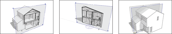
FIGURE 11-11: Moving, rotating, and copying a section plane.
When the section plane you’ve added is in position, you’re ready to control how it affects visibility in a number of other ways. See the following sections for details.
Controlling individual section planes
You can control the way section planes behave by right-clicking them to bring up a context menu, as shown in Figure 11-12. You see examples of what the following options do in the same illustration:
- Reverse: This option flips the direction of the section plane, hiding everything that was previously visible, and revealing everything that used to be behind the cut. Use this when you need to see inside the rest of your model.
-
Active Cut: The active cut is the section plane that’s actually cutting through your model; others are considered inactive. If you have more than one section plane, use Active Cut to tell SketchUp which one should be active. If you have only one section plane but can’t see the cut, check whether the cut is active. You can have more than one active section plane in your model at a time, but doing so requires that you nest, or embed, each section plane in a separate group or component. You can achieve spiffy effects with this technique, but explaining how they work in detail is beyond the scope of this book. You can read all about groups and components in Chapter 5.
- Align View: When you choose Align View, your view changes so that you look straight on at the section plane. You can use this option to produce views like the ones described in “Getting different sectional views” later in this chapter.
- Create Group from Slice: This option doesn’t have much to do with the other choices in this context menu; it’s really a modeling tool. You can use the Create Group from Slice command to do exactly what it says: Create a group from the active slice or section plane. The command is handy for creating filled-in section cuts for final presentations.

FIGURE 11-12: Right-clicking a section plane gives you some options.
Setting section-plane visibility
If you want to control the visibility of all your section planes at once, a couple menu options can help. Use both of these toggles in combination to control how section cuts appear in your model. These two options, shown on the View menu, are illustrated in Figure 11-13:
- Section Planes: This choice toggles the visibility of section-plane objects without affecting the section cuts they produce. More simply, deselecting Section Planes hides all the section planes in your model, but doesn’t turn off the section cut effect, as shown in the middle image in Figure 11-13. This view is how you probably want to show most of your sectional views, so this toggle is pretty important.
- Section Cuts: This option toggles the section cut effect on and off without affecting the visibility of the section-plane objects in your model. This choice is sort of the opposite of Section Planes, in the previous point, but it’s every bit as important.
Getting different sectional views
Using section planes, you can create a couple useful and impressive views of your model without much trouble. The second builds on the first, and both are shown in Figure 11-14. A section perspective (left) is a special view of a three-dimensional space. The second type, an orthographic view (right), is straight on and doesn’t use perspective.

FIGURE 11-13: Control section plane visibility with Section Planes and Section Cut.

FIGURE 11-14: Turn on Perspective for a section perspective; choose Parallel Projection to produce an orthographic view.
MAKING A SECTION PERSPECTIVE
If you imagine cutting a building in half and then looking at the cut surface straight on while looking inside, you have a section perspective. The section part of the term means that the building has been cut away. The perspective part indicates that objects inside the space seem smaller as they get farther away.
Section perspectives show interior space in a way most people can understand, and section perspectives look incredibly cool, too. To create a section perspective using the Section Plane tool in SketchUp, follow these steps:
-
Select the section plane you want to use to make a section perspective by clicking it with the Select tool.
When the section plane is selected, it turns blue (assuming that you haven’t changed the default colors in the Styles panel).
-
If the selected section plane isn’t active, right-click it and choose Active Cut.
Active section planes cut through their surrounding geometry. If your section plane is visible but isn’t cutting through anything, it’s not active.
-
Right-click the selected section plane and choose Align View.
This aligns your view so that it’s straight on (perpendicular) to your section plane.
-
If you can’t see your model properly, choose Camera ⇒ Zoom Extents or press Shift+Z.
This zooms your view so that you can see your whole model in the modeling window.
GENERATING AN ORTHOGRAPHIC SECTION
Ever seen a technical drawing that included top, front, rear, and side views of the same object? Chances are that was an orthographic projection, which is a common way for 3D objects to be drawn so that they can be built.
Producing an orthographic section of your model is pretty easy; it’s only one extra step beyond making a section perspective. Here’s how to do it:
- Follow steps 1 through 3 in the preceding section, as though you’re making a section perspective.
-
Choose Camera ⇒ Parallel Projection.
This switches off Perspective, turning your view into a true orthographic representation of your model. If you printed an orthographic view at a specific scale, you could take measurements from the printout.
To print a plan or section view of your model at a particular scale and you have SketchUp Pro, jump to Chapter 12 to learn about LayOut (Web: Read Chapter 13 to learn about printing to scale).
Section planes are objects in their own right. The significance of that statement is that the Outliner (see Chapter 7) can be used to find them, rename them, control their visibility, and so on just like any other object. For example, you can set up several section planes showing the plan views of each floor in a multistory building and then use the Outliner to quickly switch between the different plan views.
Animating sections with scenes
Combining section views with scenes to create an animation is both a useful and impressive way to show off your model. The basic idea is that you can use scenes to create animations where your section planes move inside your model. Here are a few reasons you may want to use this technique:
- If you have a building with several levels, you can create an animated presentation that shows a cutaway plan view of each level.
- Using an animated section plane to “get inside” your model is a much classier transition than simply hiding certain parts of it.
- When you need to show the relationship between the plan and section views for a project, using an animated section plane helps to explain the concept of different architectural views to 3D beginners.
Follow these steps to create a basic section animation; a simple example is illustrated in Figure 11-15:
-
Add a section plane to your model.
For help with this step, see “Cutting plans and sections” earlier in this chapter.
-
Add a scene to your model.
The earlier section “Creating scenes” explains how to add scenes.
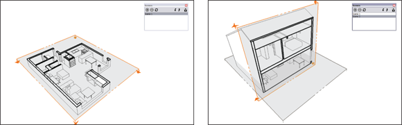
FIGURE 11-15: Making a section animation is a fairly straightforward process.
-
Add another section plane to your model.
You can add another section plane in one of two ways:
- Use the Section Plane tool to create a brand-new one. This is probably the easiest option, which makes it ideal for beginners.
- Use the Move tool to copy an existing section plane. The earlier section “Cutting plans and sections” introduces this technique.
Make sure that your new section plane is active; if it is, it cuts through your model. If it’s not active, right-click the section plane and choose Active Cut from the context menu.
-
Add another scene to your model.
This new scene remembers which is the active section plane.
-
Click through the scenes you added to view your animation.
You see an animated section cut as SketchUp transitions from one scene to the next. If you don’t, make sure that you have scene transitions enabled: Choose Window ⇒ Model Info and then choose the Animation panel in the Model Info dialog box. Make sure the Scene Transitions check box is selected. (Web: Click the Play icon in the Scenes panel.)
If you don’t like seeing the section-plane objects (the boxy things with arrows on their corners) in your animation, switch them off by deselecting Section Planes on the View menu. Then you see the section cuts without any ugly rectangles flying around. (Web: You can turn off the section planes by searching for view section planes.)
The hardest thing to remember about using scenes and section planes to make section animations is this: You need a separate section plane for each scene that you create. That is to say, SketchUp animates the transition from one active section plane to another active section plane. If all you do is move the same section plane to another spot and add a scene, this animation technique won’t work.