Chapter 3
Establishing the Modeling Mindset
IN THIS CHAPTER
![]() Understanding edges and faces
Understanding edges and faces
![]() Representing three dimensions on a two-dimensional screen
Representing three dimensions on a two-dimensional screen
![]() Inferencing like a pro
Inferencing like a pro
![]() Warming up with SketchUp
Warming up with SketchUp
![]() Lining up entities with guides
Lining up entities with guides
![]() Adding color and texture to your work
Adding color and texture to your work
When you were learning how to drive a car, you probably didn’t just get behind the wheel, step on the gas, and figure it out as you went along. (If you did, you probably have bigger things to worry about than getting started with SketchUp.) The point is, knowing some basic concepts can make your first few hours with SketchUp much more productive and fun.
So here’s the deal: This chapter has three main parts:
- The first part talks about edges and faces — the basic stuff that SketchUp models are made of.
- The second part explains how SketchUp enables you to model in 3D (three dimensions) on a 2D (flat) surface — namely, your computer screen. Understanding how SketchUp represents depth is everything when making models. If you’ve never used 3D modeling software before, pay close attention to the middle part of this chapter.
- The final part of this chapter is about the things you need to do all the time — things like navigating around your model, drawing lines, selecting things, and working with accurate measurements.
All about Edges and Faces
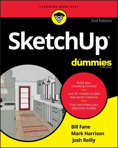
In SketchUp, everything is made up of one of two kinds of elements: edges or faces. They’re the basic building blocks of every model you’ll ever make. It’s kind of like ancient times, when everything was made of just earth, air, fire, and water.
 Collectively, the edges and faces in your model are geometry. Other modeling programs have other kinds of geometry, but SketchUp is pretty simple. That’s a good thing: You have less to keep track of.
The drawing on the left in Figure 3-1 is a basic cube drawn in SketchUp; it’s composed of 12 edges and 6 faces. The model on the right is a lot more complex, but the geometry’s the same; it’s all just edges and faces.
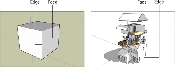
FIGURE 3-1: SketchUp models are made from edges and faces.
Living on the edge
Edges are lines. You can use lots of tools to draw them, erase them, move them, hide them, and even stretch them. Here are some things you ought to know about SketchUp edges:
- Edges are always straight. Not only is everything in your SketchUp model made up of edges, but also, all those edges are perfectly straight. Even arcs and circles are made of small straight-line segments, as shown in Figure 3-2.
- Edges don’t have a thickness. This one’s a little tricky to get your head around. You never have to worry about how thick the edges in your model are because that’s not how SketchUp works. Depending on how you choose to display your model, your edges may look like they have different thicknesses, but your edges themselves don’t have a built-in thickness.
- Just because you can’t see the edges doesn’t mean they’re not there. Edges can be hidden so that you can’t see them; doing so is a popular way to make certain forms. Take a look at Figure 3-3. On the left is a model that looks rounded. On the right, the hidden edges are visible as dashed lines. See how even surfaces that look smoothly curved are made of straight edges?
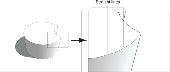
FIGURE 3-2: Even curved lines are made up of straight edges.
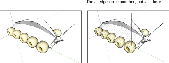
FIGURE 3-3: Even organic shapes and curvy forms are made up of straight edges.
Facing the facts about faces
Faces are surfaces. If you think of SketchUp models as being made of toothpicks and paper (which they kind of are), faces are basically the paper. Here’s what you need to know about faces:
- You can’t have faces without edges. To have a face, you need to have at least three coplanar (on the same plane) edges that are connected. In other words, a face is defined by the edges that surround it, and those edges all have to be on the same flat plane. Because you need at least three straight lines to make a closed shape, faces must have at least three sides. There’s no limit to the number of sides a SketchUp face can have, though. Figure 3-4 shows how faces can disappear when you erase an edge that defines one or more faces. We started with the model on the left and deleted the edge that completed both the top face and one of the side faces. The result, shown on the right, is that both of those faces disappeared.
- Faces are always flat. In SketchUp, even surfaces that look curved are made of multiple, flat faces. In the model shown in Figure 3-5, what look like organically shaped surfaces (on the left) are really just lots of smaller faces (on the right). Think of the many small mirrors that make up the surface of a nightclub disco ball. To make a bunch of flat faces look like one big, curvy surface, the edges between them are smoothed. You find out about smoothing edges in Chapter 6.
- Just like edges, faces don’t have any thickness. If faces are a lot like pieces of paper, they’re infinitely thin pieces of paper; they don’t have any thickness. To make a thick surface (say, a 6-inch-thick wall), you need to use two faces side by side. In SketchUp, even a solid concrete wall will be hollow.
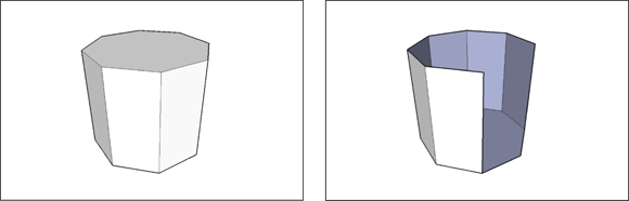
FIGURE 3-4: You need at least three coplanar edges to make a face.
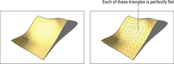
FIGURE 3-5: All faces are flat, even the ones that make up larger, curvy surfaces.
Understanding the relationship between edges and faces
Now you know that models are made from edges and faces, you’re most of the way to understanding how SketchUp works. Here’s some information that should fill in the gaps:
- Every time SketchUp can make a face, it will. There’s no such thing as a “Face tool” in this software; SketchUp just automatically makes a face every time you finish drawing a closed shape out of three or more coplanar edges. Figure 3-6 shows this in action: As soon as a line connects the last edge to the first one, SketchUp creates a face.

FIGURE 3-6: SketchUp automatically makes a face whenever you create a closed loop of coplanar edges.
- You can’t stop SketchUp from creating faces, but you can erase them if you want. If SketchUp creates a face you don’t want, just right-click the face and either choose Erase from the shortcut menu or tap the Delete key on your keyboard. That face is deleted, but the edges that defined it remain, as illustrated in Figure 3-7.
- Retracing an edge re-creates a missing face. If you already have a closed loop of coplanar edges but no face (because you erased it, perhaps), you can redraw one of the edges to make a new face. Just use the Line tool to trace over one of the edge segments, and a face reappears, as shown in Figure 3-8.
- Drawing an edge all the way across a face splits the face in two. When you use the Line tool to draw an edge from one side of a face to another, you cut that face in two. The same thing happens when you draw a closed loop of edges, such as a rectangle on a face: You end up with two faces, one “inside” the other. In Figure 3-9, we split a face in two with the Line tool and then extruded one face a little bit with the Push/Pull tool.
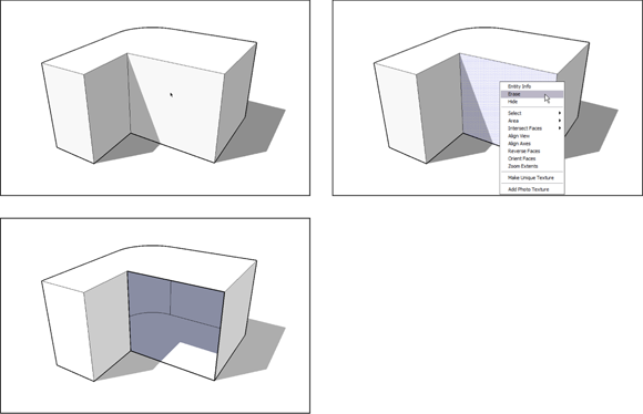
FIGURE 3-7: You can delete a face without deleting the edges that define it.
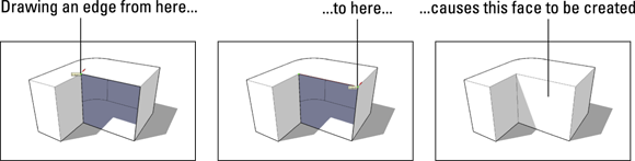
FIGURE 3-8: Just retrace any edge on a closed loop to tell SketchUp to create a new face.
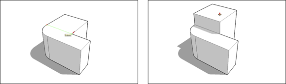
FIGURE 3-9: Splitting a face with an edge and then extruding one of the new faces.
- Drawing an edge that crosses another edge splits both edges where they touch. In this way, you can split simple edges you draw with the Line tool, as well as edges created when you draw shapes like rectangles and circles. Most of the time, this autoslicing is desirable, but if it’s not, you can always use groups and components to separate your geometry. Flip to the first part of Chapter 5 for more information.
Drawing in 3D on a 2D Screen
For computer programmers, drawing 3D objects on your screen is a difficult problem. You wouldn’t think it’d be such a big deal; after all, people have been drawing in perspective for a very long time. If Fillipo Brunelleschi could figure it out 500 years ago, why should your computer have problems?
The thing is, human perception of depth on paper is a trick of the eye. It isn’t really an optical illusion; it just looks like one. And of course, your computer doesn’t have eyes that enable it to interpret depth without thinking about it. You need to give your computer explicit instructions. In SketchUp, this means using drawing axes and inferences, as we explain in the sections that follow.
Giving instructions with the drawing axes
No, drawing axes are not used to turn your design into firewood. See the three colored lines that cross in the SketchUp modeling window? These are the drawing axes, and they’re the key to understanding how SketchUp works. Simply put, you use SketchUp’s drawing axes to figure out where you are and where you want to go in 3D space. When you’re working with the color axes, you need to keep three important things in mind:
- The red, green, and blue drawing axes define 3D space in your model. If you were standing at the spot where all three axes meet — the axis origin — the blue axis would run vertically, passing through your feet and head. The red and green axes define the ground plane in SketchUp; you’d be standing on top of them. The axes are all at right angles to one another and extend to infinity in both directions from the origin. In most computer-aided design (CAD) software, the red, green, and blue axes are referred to as X, Y, and Z, respectively.
- When you draw, move, or copy something parallel to one of the colored axes, you’re working in that color’s direction. Take a look at Figure 3-10. In the first image, we’re drawing a line parallel to the red axis, or drawing “in the red direction.” You know a line is parallel to the red axis because the line turns red and a little flag pops up to let you know. In the second image, we’re moving a box parallel to the blue (“up”) axis, or “moving in the blue direction.” The dotted blue line appears to tell you so.
-
The colored drawing axes help you tell SketchUp what you mean. In Figure 3-11, moving the cylinder in the blue direction and the green direction both involve moving the cursor up. The drawing axes help SketchUp know whether you want to move the cylinder up in space (above the ground) or back in space.
When you work in SketchUp, you use the colored drawing axes all the time. They’re not just handy, but also what make SketchUp work. They make modeling in SketchUp quick, accurate, and relatively intuitive. As you model, all you have to do is make sure that you’re working in your intended color direction: Line up your geometry with the appropriate axis, and watch the visual cues that tell you what direction you’re working in.
Keeping an eye out for inferences
If you’ve spent any time fiddling with SketchUp, you’ve noticed all the little colored circles, squares, dotted lines, yellow screen tips, and other doodads that show up as you move your cursor around your modeling window. All this stuff is referred to collectively as SketchUp’s inference engine, and its sole purpose is to help you while you build models. Luckily, it does. Without inferences (the aforementioned doodads), SketchUp wouldn’t be very useful.
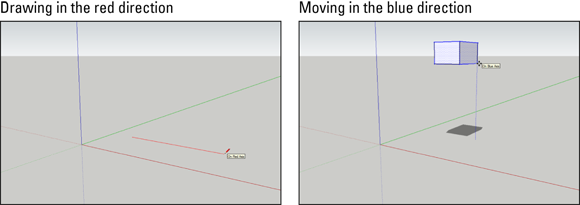
FIGURE 3-10: Visual cues tell you when you’re drawing or moving geometry parallel to a drawing axis.

FIGURE 3-11: The axes help you create 3D models on a 2D screen.
Point inferences
Generally, SketchUp’s inferences help you be more precise. Point inferences appear when you move your cursor over specific parts of your model. They look like little colored circles and squares, and if you pause for a second, a yellow label appears. The little green Endpoint inference, for example (which appears whenever your cursor hovers over the end of an edge), helps you accurately connect an edge that you’re drawing to the end of another edge in your model.
Figure 3-12 shows the point inferences that you use most often.

FIGURE 3-12: Point inferences appear when you hover your cursor over key points and help you draw accurately.
In SketchUp, lines are called edges, and surfaces are called faces. Everything in your model is made up of edges and faces.
Linear inferences
As you’ve probably already noticed, color plays a big part in SketchUp’s user interface, or the way it looks. Maybe the best example is in the software’s linear inferences — the “helper lines” that show up to help you work more precisely. Figure 3-13 illustrates the important linear inferences, and here’s a description of what they do:
- On Axis: When an edge you’re drawing is parallel to one of the colored drawing axes, the edge turns the color of that axis. In Figure 3-13, you see the On Red Axis inference.
- From Point: This one’s a little harder to describe. When a colored dotted line appears as you move your cursor, your cursor is “lined up” with the point at the other end of the dotted line. Naturally, the color of the From Point inference reflects the axis you’re lined up “on.” Sometimes, From Point inferences show up on their own, and sometimes you have to encourage them; see the section “Using inferences to help you model” later in this chapter for details.
- Perpendicular: When you draw an edge that’s perpendicular to another edge, the one you’re drawing turns magenta (reddish purple) unless it’s perpendicular to the red, green, or blue axes.
- Parallel: When the edge you’re drawing is parallel to another edge in your model, it turns magenta to let you know. You tell SketchUp which edge you’re interested in “being parallel to” by encouraging an inference. You can try this out by hovering over one edge and then starting to draw another with the Line tool.
- Tangent at Vertex: This one applies only when you draw an arc (using the Arc tool) that starts at the endpoint of another arc or an edge. When the arc you’re drawing is tangent to the other object, the one you’re drawing turns cyan. Tangent, in this case, means that the transition between the two arcs is smooth.

FIGURE 3-13: SketchUp’s linear inferences help you align new geometry with existing geometry.
 One of the most important inferences in SketchUp is one that you probably didn’t even realize was an inference: Unless you specifically start on an edge or a face in your model, you always draw on the ground plane by default. That’s right — if you just start creating stuff in the middle of nowhere, SketchUp just assumes that you mean to draw on the ground.
Using inferences to help you model
A big part of using SketchUp’s inference engine involves locking and encouraging inferences — sometimes even simultaneously. At first, these actions seem a little like that thing where you pat your head and rub your stomach at the same time, but with practice, they get easier.
- Locking inferences: If you hold down the Shift key when you see any of the first four types of linear inferences described previously, that inference gets locked — and stays locked until you release Shift. When you lock an inference, you constrain whatever tool you’re using to work only in the direction of the inference you locked.
- Encouraging inferences: Sometimes, an inference you need doesn’t show upon its own. When this happens, you have to encourage it. To encourage an inference, hover your cursor over the part of your model you want to “infer” from and then slowly go back to whatever you were doing when you decided you could use an inference.
The following example illustrates how you might lock and encourage inferences to draw a 3D model. In Figure 3-14, suppose that you want to draw a line on the blue axis that’s parallel to the right-rear corner of the block, in the same plane as the rear face and as tall as the block. Here’s how you might use inferences to help you:
 With the Line tool selected, encourage a From Point inference by hovering the cursor over the right-rear bottom corner of the block until you get an endpoint inference.
-
Now slowly move your cursor to the right, away from that corner, to encourage a From Point inference.
 Do not click that corner.
A dotted red line should trail from the pencil point back to the cube’s corner to indicate that you’re traveling parallel to the red axis. Press and hold the Shift key to lock the line in the red direction.
- Click to set the line’s starting point, release the Shift key, and then move the pencil up a bit, making sure it’s trailing a blue line.
-
Press and hold down the Shift key to lock the line in the blue direction as you draw the line.
The blue line inference becomes thicker to show that the line is locked in the blue direction.
- Move the cursor to the right-rear vertical edge of the cube while continuing to hold down the Shift key.
- When the inference to the Midpoint appears, click to set the endpoint of your new line.
Behold! You have a vertical line that meets all the specifications!
Edges must lie in the same flat plane before a face can be made. Without inferences, it’s all too easy to create a series of edges that would do Escher proud. Even just three edges that appear to connect at their ends may not be connected when viewed from a different angle.

FIGURE 3-14: Lock and encourage inferences as you draw new geometry in relationship to existing geometry.
Warming Up Your SketchUp Muscles
About eight SketchUp skills are useful every time you use SketchUp. Formal-education types would probably call them core competencies. Whatever you care to call these activities, we introduce them all in the following sections. Anytime you need a quick refresher, come back to this section.
Getting the best view of what you’re doing
Using SketchUp without learning how to orbit, zoom, and pan is like trying to build a ship in a bottle. In the dark. With your hands tied behind your back. Using chopsticks. Having just consumed the contents of the wine bottle. Get the picture?
Fully half of modeling in SketchUp uses the Orbit, Zoom, and Pan (H) tools, which let you change your view so that you can see what you’re doing. Most people who try to figure out SketchUp on their own take too long to understand the importance of these navigation tools and spend hours squinting, grunting, and having an all-around miserable time trying to get at what they’re working on. The following sections help you avoid the headache (literally).
Going into orbit
![]() Hold a glass of water in your hand. Now twist and turn your wrist around in every direction so that the water’s all over you and the rest of the room. Stop when the glass is empty. We think that’s a pretty memorable way to find out about the Orbit tool, don’t you?
Hold a glass of water in your hand. Now twist and turn your wrist around in every direction so that the water’s all over you and the rest of the room. Stop when the glass is empty. We think that’s a pretty memorable way to find out about the Orbit tool, don’t you?
Just as your wrist helps you twist and turn a glass to see it from every angle, think of using Orbit as the way to fly around your work. Figure 3-15 shows Orbit in all its glory.
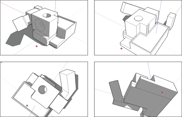
FIGURE 3-15: The Orbit tool lets you see your model from any angle.
Press and hold down your mouse’s scroll wheel, and move your mouse around. See your model swiveling? Release the scroll wheel when you’re done. Using your mouse to orbit means that you don’t have to switch tools every time you want a better view, which saves you truckloads of time. You can even do this while you’re using most other tools.
There’s a secret trick to effective orbiting: Your model twists, turns, and rotates about the center of your screen.
Zooming in and out
![]() Hold your empty glass at arm’s length. Bring the glass rushing toward you, stopping just short of smashing you in the nose. Now throw the glass across the room, noticing how it shrinks as it gets farther away. That, in a nutshell, describes the Zoom tool. We couldn’t figure out why the glass was getting bigger, but then it struck us …
Hold your empty glass at arm’s length. Bring the glass rushing toward you, stopping just short of smashing you in the nose. Now throw the glass across the room, noticing how it shrinks as it gets farther away. That, in a nutshell, describes the Zoom tool. We couldn’t figure out why the glass was getting bigger, but then it struck us …
You use Zoom to get closer to (and farther from) your model. If you’re working on something small, you zoom in until it fills your modeling window. To see everything at once, zoom out. Figure 3-16 is a demonstration.

FIGURE 3-16: Use the Zoom tool to get closer to the action.
As you’re drawing in SketchUp, you zoom in and out of your model all the time. The following tips make zooming quick and easy:
- To zoom in and out, roll your mouse’s scroll wheel. When you stop scrolling, you stop zooming and revert to your active tool.
- As you scroll, SketchUp zooms in on your cursor. Position the cursor over whatever part of your model you want to see closer (or farther away).
 Use Zoom Extents to see everything. Click the Zoom Extents button on the toolbar to have your model fill the screen.
Just panning around
![]() Using the Pan (H) tool is a lot like washing windows: You move the paper towel back and forth, but it stays flat and never gets any closer to or farther away from you. The Pan (H) tool is basically for sliding your model view around in your modeling window. To see something that’s to the right, you use the Pan (H) tool to slide your model to the left. It’s as simple as that.
Using the Pan (H) tool is a lot like washing windows: You move the paper towel back and forth, but it stays flat and never gets any closer to or farther away from you. The Pan (H) tool is basically for sliding your model view around in your modeling window. To see something that’s to the right, you use the Pan (H) tool to slide your model to the left. It’s as simple as that.
Here’s the best way to pan: Hold down your mouse’s scroll wheel button and then press and hold the left mouse button. When you do these things at the same time, your cursor temporarily turns into the Pan (H) tool, and you can move your mouse to pan. If it’s hard for you to hold down both the scroll wheel and the left mouse button, you can also hold down the scroll wheel and the Shift key.
Drawing and erasing edges with ease
Here’s the secret to modeling anything you want in SketchUp: Learn to use the Line tool without having to think too much about it. You use the Line tool to draw individual edges, and because SketchUp models are really just fancy collections of edges (carefully arranged, of course), anything you can make in SketchUp, you can make with the Line tool.
SketchUp models are made up of edges and faces. Any time you have three or more edges that form a closed shape and are on the same plane, SketchUp creates a face. If you erase an edge that defines, or borders, a face, the face disappears too. Take a look at the section “All about Edges and Faces” earlier in this chapter for more information on the relationship between edges and faces.
Drawing edges is simple. Just follow these steps:
- Start the Line tool.
Pressing the L key activates the Line tool.
- Click where you want your line to begin.
-
Move your cursor to the desired endpoint for your line, and click again to end.
As you move the cursor, notice how SketchUp stretches a rubber band back to the starting point. When you select the endpoint, the Line tool draws the line and then autorepeats, automatically starting a new line at the end of the previous one you drew.
- When you want the Line tool to stop drawing lines, tap the Esc key to snip the line at the last spot you clicked.
SketchUp lets you draw lines in two ways: You can use the click-drag-release method or the click-move-click one. We highly recommend training yourself to click-move-click. You’ll have more control, and your hand won’t get as tired. When you draw edges by clicking and dragging your mouse (click-drag-release), you’re a lot more likely to “drop” your line accidentally. Because the Line tool draws only straight lines, think about using it less like a pencil (even though it looks like one) and more like a spool of sticky thread.
![]() The Eraser tool is specifically designed for erasing edges. Activate it by pressing the E key and then click the edges you want to delete. You can also drag over edges with the Eraser, but that’s a little harder. To erase several edges at the same time, select them (selecting is explained in the upcoming section “Selecting what you mean to select”); then start the Eraser tool.
The Eraser tool is specifically designed for erasing edges. Activate it by pressing the E key and then click the edges you want to delete. You can also drag over edges with the Eraser, but that’s a little harder. To erase several edges at the same time, select them (selecting is explained in the upcoming section “Selecting what you mean to select”); then start the Eraser tool.
Injecting accuracy into your model
Most of the time, you need to make sure that your model is accurate — that what you’ve modeled is precisely the size you intend it to be. In SketchUp, the key to accuracy is the Measurements box. This powerful little text box lives in the bottom-right corner of your SketchUp window.
Here are some things the Measurements box can do:
- Make a line a certain length.
- Draw a rectangle a certain size.
- Push/Pull a face a certain distance.
- Change the number of sides in a polygon.
- Move something a given distance.
- Rotate something by a certain number of degrees.
- Make a certain number of copies.
- Divide a line into a certain number of segments.
- Change your field of view (how much you can see).
Here’s what you need to know about the Measurements box:
- You don’t have to click in the Measurements box to enter a number. This one’s a big one: SketchUp beginners often assume that they need to click in the Measurements box (to select it, presumably) before they can start typing. You don’t have to click it; just start typing, and whatever you type shows up in the box automatically. Whenever you’re drawing, the Measurements box “listens” for you to type something that controls your geometry’s precision.
- The Measurements box is context-sensitive. The box accepts values based on what you’re doing. If you’re drawing an edge with the Line tool, the box listens for a length; if you’re rotating a shape, the box listens for an angle.
-
You can set the default units for the Measurements box and override the default when necessary:
- You don’t need to type a unit if you want to use the default unit. Perhaps you want a line you’re drawing to be 14 inches long. If inches are your default unit of measurement, just type 14 in the Measurements box and press Enter; SketchUp assumes that you mean 14 inches.
- Do type a unit if you want to override the default unit. If your default is inches, and you want to draw something 14 feet long, type 14', and press Enter. You can override the default unit of measurement by typing any unit you want. If you want to move something a distance of 25 meters in an Imperial file, type 25m and press Enter.
- You can change the default units in the Model Info dialog box. You can open this dialog box from the Window menu. Click Model Info, click the Units panel, and choose your new default unit from the drop-down menu. Sorry, only standard Imperial and metric units are available — no fathoms, no furlongs, no light-years.
The default units are initially set by the template file that was used to start the drawing. - Sometimes, the Measurements box does more than one thing. In certain circumstances, you can change the box’s mode (what it “listens for”) by entering a unit type after a number. When you draw a circle, for example, the default “value” in the Measurements box is the radius. If you type 6 and press Enter, a circle radius becomes 6 inches. But if you type 6s, you’re telling SketchUp that you want 6 sides (not inches), so your circle becomes a hexagon. If you type 6, press Enter, type 6s, and press Enter again, SketchUp draws a hexagon (a 6-sided circle) with a radius of 6 inches. Note that it’s an inscribed hexagon that fits exactly inside a 6-inch circle.
- The Measurements box lets you change your mind. As long as you don’t do anything after you press Enter, you can always type a new value and press Enter again. There’s no limit to the number of times you can change your mind.
- You can use the Measurements box during an operation. In most cases, you can use the Measurements box to be precise while you’re using a tool. Here’s how that works:
- Click to start your operation (such as drawing a line or using the Move tool).
-
Move your mouse so that you’re going in the correct color direction, and be sure not to click again.
If you’re using the Line tool, and you want to draw parallel to the green axis, make sure that the edge you’re drawing is green (displays the green edge inference).
-
Without clicking the Measurements box, type the dimension you want.
The dimension appears in the box.
- Press Enter to complete the operation.
- You can also use the Measurements box after an operation. Doing so revises what you’ve just done. Suppose that you want to move a box, as shown in Figure 3-17, 5 meters in the red direction (parallel to the red axis). Here’s what you do:
- With the Move tool, click the box to pick it up.
- Move the mouse until you see the red linear inference.
-
Type 5m, and press Enter.
The box is positioned exactly 5 meters from where you picked it up. After you see that placement, however, you realize that the box needs to move a little farther.
-
Type 15m, and press Enter.
The box moves another 10 meters in the red direction.
- Keep changing the box’s position until you’re happy (or bored).
- The Measurements box tells you what value or values it’s expecting. If you select the Line tool, the Measurements box tells you it’s listening for a length. Select the Move tool, and you see that the box is expecting a distance. This feature is great because remembering everything the box can do at any given moment is pretty difficult — even for experienced SketchUp modelers.
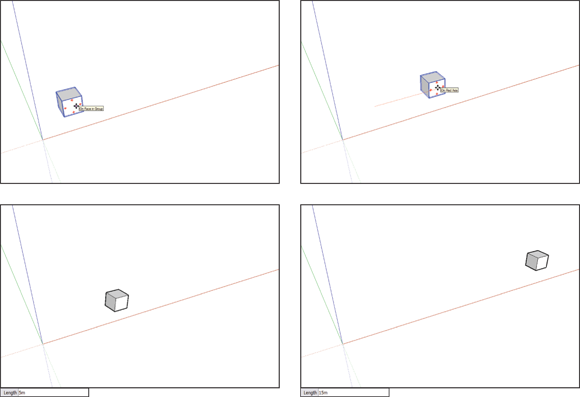
FIGURE 3-17: You can move the box 5 meters, change your mind, and move it 15 meters instead.
Selecting what you mean to select
If you want to move, rotate, copy, scale, or otherwise manipulate existing geometry in your model, you need to select it first. Your selection tells SketchUp what geometry you want to change.
![]() To select things, you use (drum roll, please) the Select (E) tool, which looks exactly the same as the Select tool in every other graphics program on the planet: It’s an arrow. That’s a good thing, because selecting isn’t the sort of thing you should have to relearn every time you pick up a new program. Here’s everything you need to know about selecting things in SketchUp:
To select things, you use (drum roll, please) the Select (E) tool, which looks exactly the same as the Select tool in every other graphics program on the planet: It’s an arrow. That’s a good thing, because selecting isn’t the sort of thing you should have to relearn every time you pick up a new program. Here’s everything you need to know about selecting things in SketchUp:
-
 Technically, every single thing you see in your modeling window is an entity. SketchUp has three kinds of entities:
 - Elements are basic pieces of geometry, like edges and faces.
- Objects are made up of elements. Components and groups, which we cover in Chapter 5, are objects. Anytime you want to make a separate thing with its own name and metadata, you make an object. In SketchUp, objects are everywhere.
- Annotations are things like text, guides, dimensions, and section planes. Annotations is kind of a catch-all category; anything that isn’t an element or an object is an annotation.
- Click anything in your model to select it — while you’re using the Select (E) tool, of course.
-
To select more than one thing, hold down the Shift key while you click all the things you want to select.
The Shift key works both ways when it comes to the Select (E) tool. You can use it to add to your set of selected things (as we mention earlier), but you can also use it to subtract something from your selection. In other words, if you have a bunch of stuff selected, and you want to deselect something in particular, just hold down Shift while you click it; it isn’t selected anymore. - Selected entities in SketchUp look different depending on what they are:
- Selected edges turn blue.
- Selected faces change from plain gray to blue-gray (if you’re using the default style).
- Selected groups and components have a blue box around them.
- Selected annotations turn blue.
-
A much fancier way to select things in your model is to double- and triple-click them. When you double-click a face, you select that face and all the edges that define it. Double-clicking an edge gives you that edge plus all the faces that are connected to it. When you triple-click an edge or a face, you select the whole conglomeration that it’s part of. See Figure 3-18.
-
You can select several things at the same time by dragging a box around them. You have two kinds of selection boxes; the one you use depends on what you’re trying to select (see Figure 3-19):
- Window selection: If you click and drag from left to right to make a selection box, you create a window selection. In this case, only things that are entirely inside your selection box are selected.
- Crossing selection: If you click and drag from right to left to make a selection box, you create a crossing selection. With one of these, anything your selection box touches (including what’s inside) is selected.
The Window selection box (left to right) is shown using solid lines, while a Crossing box (right to left) uses dashed lines.
Just because you can’t see something doesn’t mean it isn’t selected. Whenever you make a selection, it’s a very good idea to orbit around to make sure you have only what you intended to get. Selecting too much is an easy mistake to make.
Moving and copying like a champ
![]() To move, stretch, or copy geometry in SketchUp, use the Move tool. That’s right, the Move tool isn’t just for moving, and this section explains all the Move tool secrets that will help you quickly advance to more complex 3D modeling.
To move, stretch, or copy geometry in SketchUp, use the Move tool. That’s right, the Move tool isn’t just for moving, and this section explains all the Move tool secrets that will help you quickly advance to more complex 3D modeling.
Moving things
Using the Move tool usually involves several steps:
- Tap the spacebar to invoke the Select (E) tool.
- Select the entity or entities that you want to move.
- Activate the Move tool.
-
Click a starting point for the move and then move the cursor.
As with most SketchUp tools, it’s best not to hold the mouse button down while moving; just click at the destination.
- Click the destination point.
The maneuver isn’t complicated, but getting the hang of it takes a bit of practice.
Here are tips for using the Move tool successfully:
- Click, move, and click; don’t drag your mouse. Many new SketchUp users are tempted to move stuff by clicking and dragging. That works, but in the long run, moving things is harder that way. Instead, practice clicking to pick something up, moving your mouse without holding down any buttons, and clicking again to put down whatever you’re moving.
- Click a point that will let you position whatever you’re trying to move. Figure 3-20, for example, shows two boxes. To stack one on top of the other precisely, you can’t just click anywhere on the first box and move it over the other one. You have to click the bottom corner of the soon-to-be top box and move the cursor over the top corner of the bottom box.
- Press the Esc key to cancel a move operation. When you start to move something (on purpose or accidentally), it’s tempting to use Move to put things back the way they were. Inevitably, Move messes up your model. Instead, the quickest and easiest way to get out of a Move operation and keep your model intact is to tap the Esc key.
- Watch for helpful inferences. To move something in one of the colored directions, wait until you see the dotted On Axis linear inference appear; then hold down Shift to lock yourself in that direction. For more information about using SketchUp’s inference engine, check out the earlier section “Keeping an eye out for inferences.”
- Move precisely with the Measurements box. You can move things precise distances with the Measurements box; see “Injecting accuracy into your model” earlier in this chapter.
- Watch where you are going. In the current release of SketchUp, if you orbit during the move so that you can no longer see the starting point on the selected objects, the objects become semitransparent, allowing you to find the desired destination point more easily.

FIGURE 3-20: To move things precisely, choose precise points to grab things and put them down.
Shaping forms with the Move tool
SketchUp’s Move tool isn’t just for moving whole objects. You can also use this tool to change the shape of your model. To do this, move a vertex (the place where edges’ endpoints come together), an edge, a face, or a combination of any of these. By moving only certain entities (all the things we just mentioned), you can change the shape of your geometry pretty drastically, as shown in Figure 3-21.
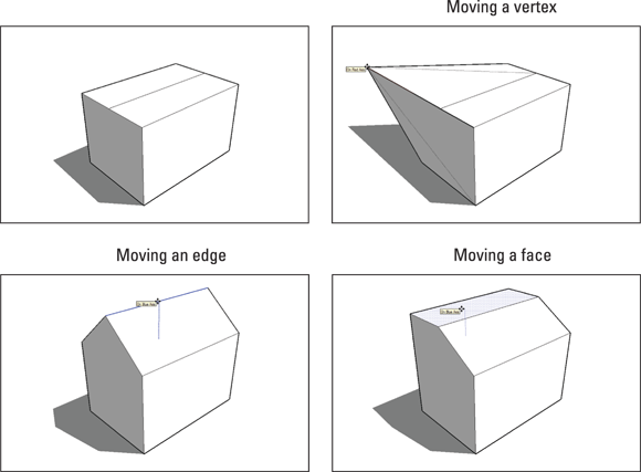
FIGURE 3-21: You can use the Move tool on vertices, edges, and faces to model different forms.
Using the Move tool to create forms (instead of just moving them around) is an incredibly powerful way to work but isn’t particularly intuitive. After all, nothing in the physical world behaves like the Move tool. You can’t just grab the edge of a hardwood floor and move it up to turn it into a ramp in real life. In SketchUp, you can — and should.
To preselect or not to preselect
The Move tool works in two ways, and you’ll eventually need to use them both, depending on what you’re trying to move:
- Moving a selection: This process is the basic one, described earlier in this chapter in “Moving and copying like a champ.” When you select one or more entities, the Move tool moves only the selection. This behavior is handy when you need to move more than one thing at the same time. Figure 3-22 shows how to move selected items with the Move tool.
- Moving without a selection: If you start the Move tool without making a selection first, you can click anything in the drawing window to move it around. Only the thing you click moves. This technique can create some unpredictable results, however, so we generally advise using the preselect method.
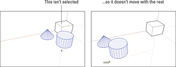
FIGURE 3-22: Using the Move tool when you have a selection moves only the things in that selection.
Making copies with the Move tool
Lots of folks spend time hunting around in SketchUp, trying to figure out how to make copies. It’s very simple: You just press a modifier key — a key on your keyboard that tells SketchUp to do something different — while you’re using the Move tool. Instead of moving something, you move a copy of it. Here are a couple things to keep in mind:
-
Press the Ctrl key (Mac: Option) to create a copy. You can press the modifier key before or after you click the entity you want to move. When the Move tool is in Copy mode, a little + appears next to the Move cursor, and your copy moves when you move your mouse. Figure 3-23 shows this in action.
If you decide that you don’t want to make a copy, just press the Ctrl key (Mac: Option) again to toggle back to Move; the + sign disappears.
- Copying is just like moving except that you’re moving a copy. All the rules for using the Move tool apply to making copies too.

FIGURE 3-23: Press Ctrl (Mac: Option) to tell SketchUp to make a copy while you move something.
-
To make more than one copy at a time, use the Measurements box. Suppose that you want to make five equally spaced copies of a column, as shown in Figure 3-24. First, move a copy to where you want the last column to be; then type 5/ and press Enter. SketchUp makes five copies of the column and spaces them evenly between the first and last column in the row. Neat, huh?
To set a precise distance between your copies, move a copy to set the distance between each copy, type 5x, and press Enter.

FIGURE 3-24: Use the Measurements box to make multiple copies.
Rotating the right way
![]() The Rotate (Q) tool spins geometry based on an angle you specify. No surprises there. But the Rotate (Q) tool also has a trick up its sleeve that most new modelers don’t discover until hours after they could’ve used it. First things first, though:
The Rotate (Q) tool spins geometry based on an angle you specify. No surprises there. But the Rotate (Q) tool also has a trick up its sleeve that most new modelers don’t discover until hours after they could’ve used it. First things first, though:
- It’s better to preselect. As with the Move tool, rotating something you’ve already selected is usually easier.
- The Rotate(Q) tool can make copies, too. Press the Ctrl key (Mac: Option) to switch between rotating your original and rotating a copy. You can also make several copies arranged in a circle or along an arc. Check out the earlier section “Making copies with the Move tool” to read about using x and / to create multiples.
- You can be precise. The Measurements box enables you to type exact angles while you’re rotating. Take a look at “Injecting accuracy into your model” earlier in this chapter to find out more.
Using Rotate (Q): The basic method
Follow these steps to rotate things in your model:
- Select everything you want to rotate.
- Activate the Rotate (Q) tool.
-
Click to establish an axis of rotation.
Your axis of rotation is the theoretical line around which your selected entities will rotate; picture the axle of a wheel. Although it’d be nice if SketchUp drew the axis of rotation in your model, you just have to imagine it.
As you move the Rotate tool’s big protractor cursor around your screen, the cursor sometimes changes orientation and color. When you hover over a face, the cursor realigns itself to create an axis of rotation that’s perpendicular to that face. When the cursor is red, green, or blue, its axis of rotation is parallel to that colored axis. You can (and should) use inference locking when you’re using the Rotate (Q) tool. Just hover over any face in your model that’s perpendicular to the axis of rotation you want, hold down the Shift key to lock in that orientation, and click where you want your axis to be. See “Using inferences to help you model” earlier in this chapter to read all about it. -
Click again to start rotating.
Clicking part of the thing you’re rotating is helpful, especially if you’re rotating visually instead of numerically (by typing an angle).
-
Move your mouse; then click again to finish rotating.
If you like, now is a good time to type a rotation angle and press Enter. As with everything else in SketchUp, you can be as precise as you want or need to be.
Using Rotate (Q): The not-so-basic method
The basic method of using the Rotate (Q) tool is fine when you need to rotate something on the ground plane, but this method isn’t as useful when your axis of rotation isn’t vertical. Finding a face to use to orient your cursor can be tricky or impossible, and that’s where a lot of SketchUp modelers get hung up.
With this not-so-basic rotation method, you can establish a precise axis of rotation (the invisible line around which you’re rotating) without having any existing faces to use for orientation. This makes rotating things about a million times easier.
In this case, using the Rotate (Q) tool goes from being a five-step operation to a seven-step one. Check out Figure 3-25 for a visual explanation:
 Select everything you want to rotate.
- Activate the Rotate (Q) tool.
- Click to establish your axis of rotation, but don’t let go; keep your finger on your mouse button.
-
Drag your cursor around (still holding down the mouse button) until your axis of rotation is where you want it.
As you drag, notice that your Rotate protractor changes orientation; the line from where you clicked to your cursor is the axis of rotation.
- Release your mouse button to set your axis of rotation.
- Click (but don’t drag) the point at which you want to pick up whatever you’re rotating.
- Click again to drop the thing you’re rotating where you want it.
Making and using guides
Sometimes, you need to draw temporary lines while you model. These temporary lines, or guides, are useful for lining up things, making things the right size, and generally adding precision and accuracy to what you’re building.
Guides are special entities that you create when and where you need them. They aren’t part of your model because they’re not edges or faces, so you can choose to hide them or delete them; like other annotations, they don’t affect the rest of your geometry.
Figure 3-26 shows an example of guides in action. The guides are positioned 12 inches from the wall and 36 inches apart to draw the sides of a doorway. Another guide (6 feet, 8 inches from the floor) indicates the top. With these guides in place, you can easily draw a rectangle, bounded by your guides, that you know is exactly the right size and in the correct location.
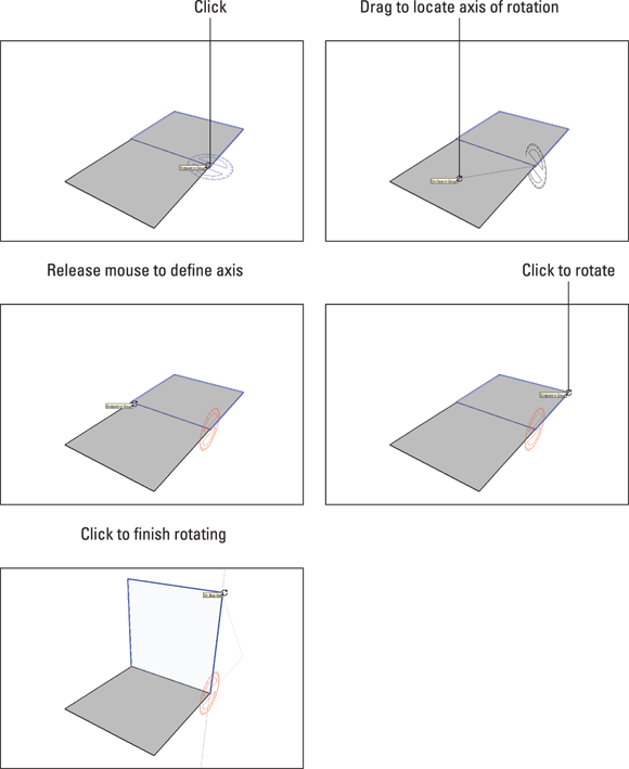
FIGURE 3-25: Define a custom axis of rotation by click-dragging.
Creating guides with the Tape Measure tool
![]() You can create three kinds of guides, and you use the Tape Measure (T) tool to make them all, as shown in Figure 3-27.
You can create three kinds of guides, and you use the Tape Measure (T) tool to make them all, as shown in Figure 3-27.
- Parallel guide lines: To create a guide that's parallel to an edge, select the Tape Measure tool, and click anywhere (except the endpoints) along an edge. Then move your mouse, and a parallel dashed guide appears. Click again to place the guide wherever you want.
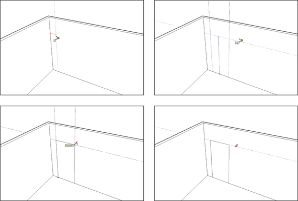
FIGURE 3-26: Use guides to measure things before you draw.
- Linear guide lines: To create a guide along an edge in your model, click anywhere along the edge except on either endpoint. Then click again anywhere else along the edge.
- Guide points: You may want to place a point somewhere in space; you can do exactly that with guide points. With the Tape Measure tool, click an edge’s endpoint and then click again somewhere else. A little x appears at the end of a dashed line. That’s your new guide point.
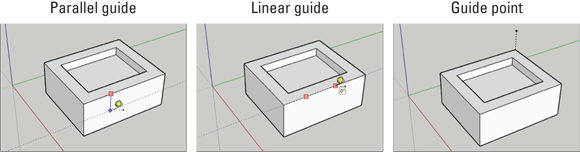
FIGURE 3-27: Use the Tape Measure tool to create guide lines and points.
Here’s an important point about the Tape Measure tool: It has two modes, and it creates guides in only one of them. Pressing the Ctrl key (Mac: Option) toggles between the modes. When you see a + next to your cursor, your Tape Measure can make guides; when there’s no +, it can’t.
Using guides to make your life easier
As you’re working in this software, you’ll find yourself using guides all the time; they’re an indispensable part of how modeling in SketchUp works. Here’s what you need to know about using them:
- Position guides precisely, using the Measurements box. Check out “Injecting accuracy into your model” earlier in this chapter to find out how.
- Erase guides one at a time. Just click or drag over them with the Eraser tool to delete guides individually. You can also right-click them and choose Erase from the shortcut menu.
- Erase all your guides at the same time. This operation comes in two flavors:
- Desktop: Choose Edit ⇒ Delete Guides.
- Web: Enter guides in the search box and then click Delete Guides.
- Hide guides individually. Right-click a single guide and choose Hide from the shortcut menu to hide it.
-
Hide or unhide all guides at the same time. This operation also comes in two flavors:
- Desktop: Choose View ⇒ Guides to alternate between showing or hiding all guides.
- Web: Enter guides in the search box and then click the View Guides button to toggle between visible or hidden.
It’s usually a good idea to hide your guides instead of erasing them, especially while you’re still modeling.
- Select, move, copy, and rotate guides just like any other entities in your model. Guides aren’t edges, but you can treat them that way a lot of the time.
Painting your faces with color and texture
When you’re adding colors and textures — collectively referred to in SketchUp as materials — to your model, look no further than the Materials panel and the Paint Bucket (B) tool. Chapter 2 introduces this winsome pair and provides a workflow for adding materials to your model. This section offers a more in-depth introduction to your options.
The Materials panel
The Materials panel looks different in the Windows and Mac versions of SketchUp, but both versions do basically the same thing. By default, the Materials panel appears on the Default Tray (Windows only). If the panel is ever hidden, and you need to reopen it, choose Window ⇒ Default Tray ⇒ Materials (Mac: Window ⇒ Materials).
In SketchUp, you can choose either of two kinds of materials to apply to the faces in your model:
- Colors: These simple colors are always solid colors. You can’t have gradients (one color fades into another), but you can make pretty much any color you want.
-
Textures: A SketchUp texture is a tiny image that’s tiled to cover a face. If you paint a face with, say, a brick texture, what you’re really doing is telling SketchUp to cover the surface with however many brick-photo tiles it takes to do the job. The preview image you see in the Materials panel is actually a picture of a single texture image tile.
SketchUp comes with a whole bunch of textures, and thousands more are for sale online. If that’s still not enough, you can make your own (though the process is well beyond the scope of this humble tome). For details on advanced techniques such as creating a custom texture, check out the SketchUp Help Center (
https://help.sketchup.com).
The following facts about SketchUp materials are also handy to know as you work with them:
- Materials can be translucent. Sliding the Opacity slider makes the material you’ve selected more or less translucent, which makes seeing through windows in your model a lot easier. In Windows, you find the Opacity slider on the Edit tab.
- Textures can have transparent areas. If you take a look at the materials in the Landscaping, Fencing, and Vegetation library, you’ll notice that a lot of them look kind of strange; they have areas of black that don’t seem right. These black areas are areas of transparency: When you paint a face with one of these textures, you can see through the areas that look black.
There’s a third thing (besides colors and textures) that you can apply to the faces in your models: photos. In fact, photo-texturing is an incredibly important part of some SketchUp workflows. As such, we dedicate a good portion of Chapter 8 to the subject of modeling with photographs.
The Paint Bucket (B) tool
![]() Activating the Paint Bucket (B) tool automatically opens the Materials panel so that it’s handy. Here’s everything you need to know about the Paint Bucket (B) tool:
Activating the Paint Bucket (B) tool automatically opens the Materials panel so that it’s handy. Here’s everything you need to know about the Paint Bucket (B) tool:
-
You fill it by clicking in the Materials panel. Just click a material to load your bucket and then click the face you want to paint.
The converse is also true: If you click a material or color in the Materials panel, it launches the Paint Bucket (B) tool and fills it with the selected color or material. - You have a much wider range of choices than you may think. As mentioned in Chapter 2, if you don’t see a color or texture you like, click the down arrow at the end of the window that says something like Asphalt and Concrete, Metal, or Patterns. This produces a list of 16 categories of materials, colors, and patterns,
- What if you don’t like the available carpet colors? Or any of the other materials, for that matter? No problem. Just click the Edit tab and pick a color — any color — to apply to your choice of material.
- Holding down the Alt key (Mac: ⌘ ) switches to the Sample tool. With the Sample tool, you can click any face in your model to load your Paint Bucket with that face’s material. Release the Alt key to revert to the Paint Bucket (B) tool.
- Holding down the Shift key paints all similar faces. Don’t like the dark brick on your house model? Select a new material in the Materials panel, hold down the Shift key, and click any face with the brick applied. In Figure 3-28, the Paint Bucket (B) tool is ready to change the dark brick to a lighter option, which you see as the active material in the top-left corner of the Materials panel. When you’re done, all faces in your model that match the one you click are painted with the new material. If things don’t turn out the way you want, just choose Edit ⇒ Undo to go back a step.

FIGURE 3-28: Press Shift and click with the Paint Bucket (B) tool to replace one material with another.