
6
Topology on a Humanoid Body
With the head done in the previous chapter, we can move on to the rest of the body. On the head, we began working on the most detailed part, which is the face. We broke down the face into even more detailed areas, such as the nose, mouth, and eyes. Once we finished these areas, we only had to focus on connecting them and then filling out the less important parts of the head.
Next, we are going to use this same idea to approach the body. We will start with the detailed areas, and then work out from there. The hand is usually the most detailed part of the body, so that will be the section of the body we will start our work from. Next, we will look at the shoulder, and connect it to the neck. Then, we will move on to the hip and crotch area. Finally, we will join them all together.
In this chapter, we will be learning about the following subjects:
- How to retopologize a hand
- How to retopologize shoulders
- How to retopologize hips
- Connecting the body parts together
How to retopologize hands
When approaching hands, we need to break them down into parts. Thankfully, with the hand, it is not too difficult, as they are very naturally broken up into segments. The fingers and the palm make up the detailed areas of the hand. This makes it easy to start, but it also complicates joining the sections together. Ideally, you would have the detailed areas separate from each other. This makes it much easier to connect them because the area in between is less important. Because these detailed areas are right next to each other, we need to be more creative with how we join them together to ensure good and even topology. You can see our hand in Figure 6.1.
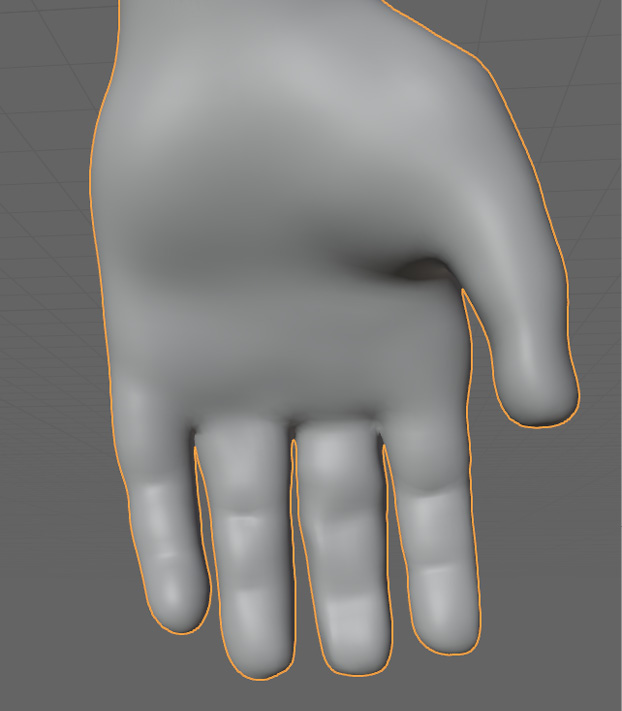
Figure 6.1 – Close up of a hand
On the hand, the fingers are a good place to start. The tip of the finger is usually the most detailed part of the finger, especially if the character has fingernails. In this case, our character does not, but the tips of the fingers are still the most detailed part of the fingers, so we will start there. Figure 6.2 shows us the tips of the fingers, and how we started them.
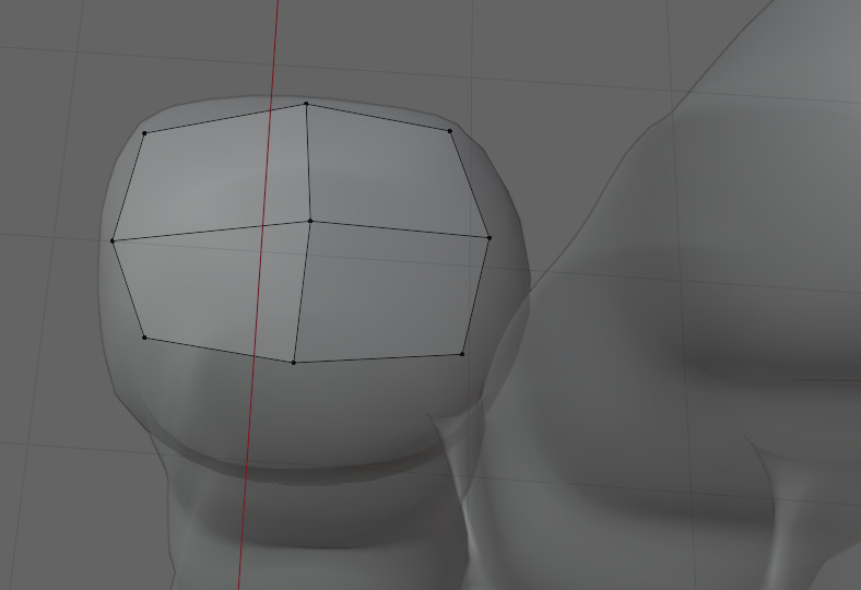
Figure 6.2 – Close up of a fingertip with preliminary vertices
A simple grid was snapped to the tip of this index finger. We want to keep the mesh as minimal as possible to keep the rest of the hand at a reasonable quad count. In Figure 6.3, we extruded the mesh inward by selecting all of the faces and pressing E.

Figure 6.3 – Faces extruded and snapped to the fingertip
Extruding the mesh inward like this and snapping it to the model allows us to add a little more detail without affecting other parts of the model. The next step is to extrude the border of this plane down to the first knuckle and snap it in place, as in Figure 6.4.
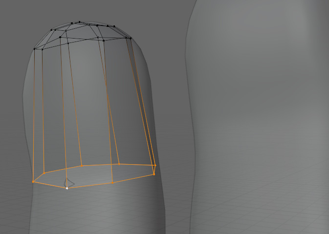
Figure 6.4 – The border of the plane snapped in place at the first knuckle
This makes it easier to add loop cuts afterward because Blender will interpolate the loop cut between one end and the other. Figure 6.5 shows this in a little more detail:
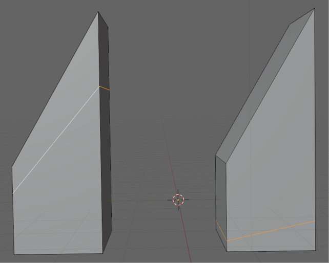
Figure 6.5 – Interpolation of the loop cuts
These are identical shapes with different loop cuts applied to them. The one on the left has a loop cut closer to the top, and the shape on the right has a loop cut closer to the base. As the loops get closer to the top, they will look more like the top loop, and as they get closer to the bottom, they will look more like the bottom. You can see a shape with multiple loop cuts in Figure 6.6 to help illustrate this further.
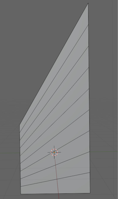
Figure 6.6 – Shape with multiple loop cuts showing interpolation of the loops
We will do the same thing with the finger after we extrude it all the way to the base of the finger. First, we need to extrude it to the next knuckle, then to the base, and snap both of those extrusions into place, as in Figure 6.7.
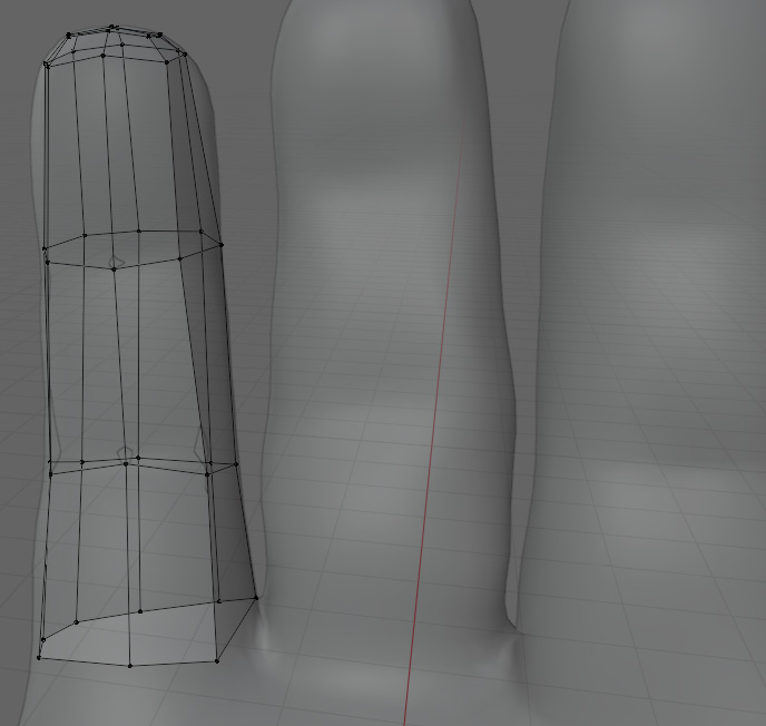
Figure 6.7 – Finger with extrusions snapped into place
This is a good place to duplicate this mesh to the other fingers. To duplicate the mesh, select the whole mesh, and press Ctrl + D. After the mesh is duplicated, move it to the next finger and snap it in place. When you have done the four fingers other than the thumb, it should look like Figure 6.8.

Figure 6.8 – Mesh duplicated and applied over all fingers except the thumb
With the fingers duplicated, we can add details such as the knuckles. For the knuckles, we will be using the same technique we used on the elbow joint in Chapter 3 under the Fixing the topology on an elbow joint section. First, we will add loop cuts in between the joints of the finger, as shown in Figure 6.9.

Figure 6.9 – Loop cuts added between finger joints
Do not worry about snapping these to the hand just yet. Instead, we are going to continue with the joint. To make the knuckles, just select the faces on the top and bottom of the edge loops selected, as shown in Figure 6.10.
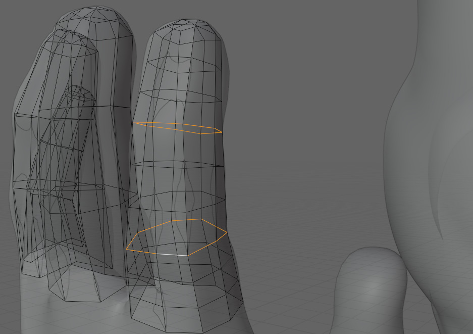
Figure 6.10 – Faces selected to mark the knuckles
When selecting the faces, stop your selection halfway around the back of the joint. It should look something like Figure 6.11 when you are done.

Figure 6.11 – Faces selected to inset into the knuckles
With these faces selected, we can inset the faces by pressing I. Figure 6.12 shows the finger after the inset.

Figure 6.12 – Finger after being inset
Repeat this step for the other fingers as well. You can refrain from manually snapping these vertices to the hand as well. Because we copied the fingers and snapped them to the joints before, we can apply a shrink wrap modifier to snap these vertices for us. These are the steps to apply the modifier:
- First, go to the Modifier tab and select the Add Modifier tab, as shown in Figure 6.13:

Figure 6.13 – Menu under the Add Modifier tab
- After selecting the Shrinkwrap modifier from the Add Modifier tab, select the dense mesh that you have been snapping to manually.
- To select the dense mesh, click on the Target option on the Shrinkwrap modifier. And in the dropdown, select the dense mesh. In this case, I have called the dense mesh Monkey Man. With the dense mesh selected as the target, the modifier should look like Figure 6.14.

Figure 6.14 – Modifier with dense mesh selected
- Finally, we can select the arrow pointing down on the modifier, and apply the modifier. You can see this in Figure 6.15:
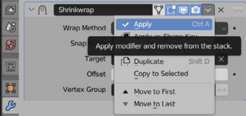
Figure 6.15 – Menu to apply the modifier
After smoothing the topology to match the shape of the knuckles a little better, Figure 6.16 is what we are left with:
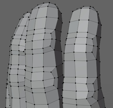
Figure 6.16 – Fingers with modifiers applied
Next, we can start on the palm. You could also start with the thumb, but it can be difficult to join things up. Using the thumb to accommodate the geometry usually makes things easier. So, as we did on the face, we need to outline the creases and peaks. Figure 6.17 shows the simple outline.

Figure 6.17 – Palm with creases and peaks outlined
With the lines laid out, we can fill them in with simple grids, as in Figure 6.18.
Figure 6.18 – Palm partly filled with simple grids
Now, we can flip our hand around and do the same thing with the back of the hand. In this case, it should be pretty easy. Figure 6.19 shows the back of the hand with the sculpted mesh hidden.

Figure 6.19 – The back of the hand with faces on it
Next, we join our fingers to the rest of our hand on the front and the back, as in Figure 6.20.
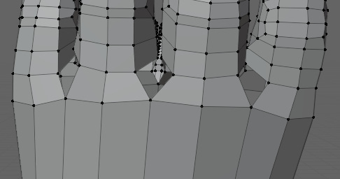
Figure 6.20 – Fingers joined to the rest of the hand
You may have noticed this left a few gaps between the fingers, but these are easily fixed. Figure 6.21 shows the area filled in between the fingers.
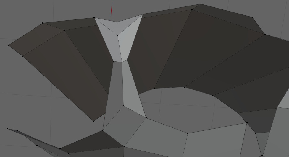
Figure 6.21 – Area between the fingers filled
Repeat this joint for all of the fingers. That leaves the gap around the outside of the hand, and in particular, two tricky loops, one of which is highlighted in Figure 6.22.
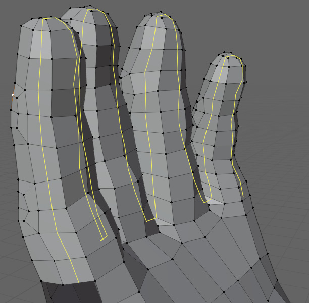
Figure 6.22 – Loop cut showing the flow of topology through the faces
All we have to do is join the sides together and prepare to extrude the thumb. Figure 6.23 shows the mesh before extruding the thumb.
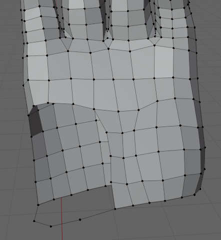
Figure 6.23 – Mesh before extruding the thumb
Next, we can select all of the vertices surrounding the thumb, and extrude them out by pressing E. Lastly, we just need to snap the vertices of the extrusion to the first joint of the thumb. But we have to be very careful when we join these faces together. Figure 6.24 shows a highlighted loop going around the hand, and the completed thumb extrusion. We need to make sure that all of these loops connect back to themselves.
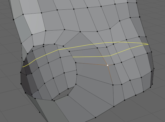
Figure 6.24 – Loop cut showing an example of a loop that needs to be connected to itself
It is helpful to join these together at this point, and then add loop cuts as needed to get it to match the shape of the thumb. You can see the loop completed in Figure 6.25.

Figure 6.25 – All of the loops connected into themselves
After filling the remaining gaps from the other direction and snapping the vertices, it should look like Figure 6.26.
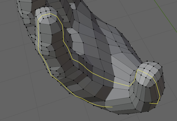
Figure 6.26 – The flow of topology on the snapped faces
The hand also follows our topology rules when we send loop cuts in this direction too. Now, all we have to do is add some loop cuts around it and inset our knuckle as we did on the other fingers. Figure 6.27 illustrates the finished hand.
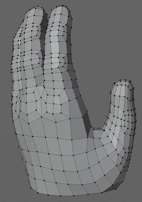
Figure 6.27 – The completely retopologized hand
All of the sections of the hand follow our topology rules, so we should not have to worry about the hand anymore. Thankfully, it is all downhill from here. With the hand done, we have to figure out how we are going to connect it to the rest of the body.
How to retopologize shoulders
Before getting up to the shoulder, we have to extrude our wrist up to the elbow, then to the shoulder, just like our fingers. You can see the arms extruded and with loop cuts in Figure 6.28.

Figure 6.28 – Arms with loop cuts
Now we can start on our shoulder. Just like our face and hand, we are going to start by laying out some guiding lines. Figure 6.29 shows the lines laid out for the shoulder.
Figure 6.29 – Shoulder with guiding lines
And like the areas of detail before, we just need to fill these in, as in Figure 6.30.

Figure 6.30 – Shoulder filled in with faces
With the shoulders roughed out, we can bring the neck down to the shoulders. For this model, I simply adjusted the loops on the collarbone to match the loops on the neck and did a straight connection, as shown in Figure 6.31.
Figure 6.31 – Head, shoulders, and arms connected with edges
Now, we just have to work our way down the chest, and then do the lower body. But first, we should look down at the hips, and then focus on connecting the two parts of the body.
How to retopologize hips
The hips of the model will be done in a way that should seem familiar, as we have looked at a shape similar to a hip when we used the pant model in Chapter 2 and Chapter 4. You can see the guiding lines in Figure 6.32.

Figure 6.32 – Guiding lines across the hips
After connecting the guiding lines, the model should look something like Figure 6.33.

Figure 6.33 – Hips with guiding lines connected
With the front done, we can move on to the back. This will be a bit different from the front, but still not too difficult. You can see the guiding lines for the back in Figure 6.34.
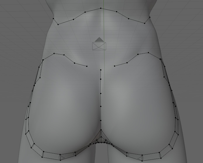
Figure 6.34 – Back with guiding lines
With everything connected, the back should look like Figure 6.35.
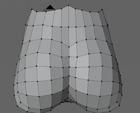
Figure 6.35 – Back with guiding lines connected
And with that, our hip is complete, and our model is just missing his torso now. You can see what we have left to do in Figure 6.36.
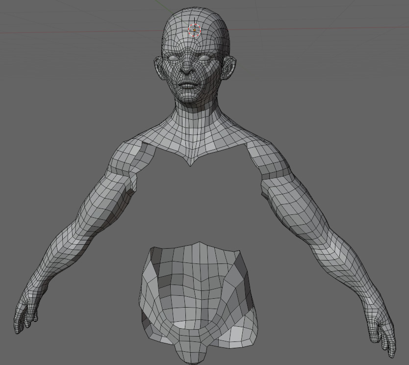
Figure 6.36 – Model with parts remaining to be retopologized
The gaps left over in the mesh will be filled in the next section to complete our torso.
Connecting the body parts together
For the chest, instead of just lines, we are going to use full faces. Because we have the sections already fully modeled, it can be helpful to visualize how the topology is going to react with full faces. Figure 6.37 shows what this looks like.

Figure 6.37 – Chest with full faces as guides
Again, these faces just outline the major shapes of the model, so that we can fill them in later. The filled-in model can be seen in Figure 6.38.

Figure 6.38 – The completely filled-in model without the legs
With that, we are almost done with the body. All that is left is to extrude the legs from the hip. All we have to do to achieve this is repeat what we did for the arms and finger:
- Extrude the mesh to each joint.
- Loop cut to get even quads.
- Then, inset the faces on the outside of the joint.
After extruding out the legs and using a shrinkwrap modifier as we did on the arms and fingers, the retopology is done. We should be left with something like Figure 6.39.
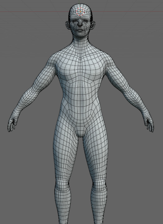
Figure 6.39 – The complete model of the body
Summary
In this chapter, we learned how to retopologize a hand, shoulder, and hip area. We also went through how interpolation works for loop cutting and learned how to connect detailed areas together.
By this point, you should have a comfortable understanding of the topology rules, and a good idea of what to do when approaching a new section of a mesh. While Chapter 5 and this chapter focused on organic and flowing topology, Chapter 7 will take a closer look at hard surface retopology using quads. In the next chapter, we will be confronted with topology situations that we would not ordinarily encounter when performing organic modeling.