
8
Optimizing Geometry for a Reduced Triangle Count
All of the chapters leading up to this final chapter have been reinforcing the same ideas. Each chapter has been laying out the steps to good quad-based topology. The reason we chose this workflow was to ensure that we had a model that would be easy to work with throughout the model creation process. From deformations to UV unwrapping, quad-based topology will give you the cleanest and easiest result when done right. In this chapter, we are going to be breaking those rules.
This chapter is going to be all about reducing the triangle count on the models that we made in the last three chapters. We will start by learning why we might want to break our topology rules in the first place. Next, we will talk about some of the tools we will use to help us optimize. Then, we will go straight into optimizing a hard-surface model and finish with a character model.
In this chapter, we will be learning about the following subjects:
- Why we optimize topology
- Optimizing hard-surface meshes
- Optimizing deforming meshes
Why we optimize topology
When done correctly, quad-based topology should leave you with a model that is ready for just about everything, but having that freedom and flexibility comes with a cost. This cost is an increased number of faces on a mesh and is most evident on hard-surface models. The workflow we have been using up to this point has had us starting on the detailed areas first, then connecting those areas afterward. You may have noticed that these detailed areas have a lot of curves and complex shapes, but the areas in between that we connect them with are usually much flatter. You can see this transition in Figure 8.1.
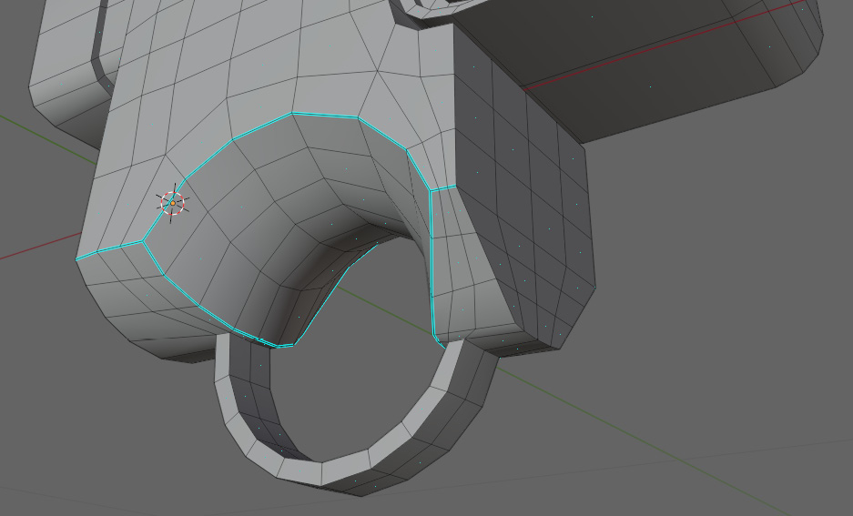
Figure 8.1 – Flatness evident in connecting areas
It is in these flat areas that there are a lot of faces that are not contributing to the shape of the blaster. That is our objective when optimizing topology; we are trying to remove as many of these unnecessary faces as possible. The question still remains: why do we want to reduce the number of faces in the first place? The answer is really quite simple. It is to reduce the performance impact of the model. This impact has two causes. The first is that the more faces there are, the more work the rendering engine is going to have to do calculating the light on each face. The second cause stems from the number of faces that the 3D software has to keep track of simultaneously. Adding a few thousand faces to a scene makes little difference on modern systems with modern software. However, when you start adding faces to multiple objects in a scene that has thousands of assets, they can start to add up quickly. That is why we are going to start by optimizing the blaster we made in the last chapter.
Optimizing hard-surface meshes
There are a few helpful tools we are going to introduce before getting into the optimization. The first tool is called vertex slide. Vertex slide allows us to slide a vertex along an edge. To use vertex slide, follow these steps:
- Double-tap G, and you should get a line going across your edge, like in Figure 8.2.

Figure 8.2 – Vertex slide initiated
- You can now move this vertex along any of the edges that the vertex is connected to, as shown in Figure 8.3.

Figure 8.3 – The vertex sliding along the edge
This will blend nicely into our second tool called Auto Merge. Auto Merge merges vertices that are within a certain distance of each other. You can enable Auto Merge in the Active Tool and Workspace settings, as shown in Figure 8.4.

Figure 8.4 – Enabling Auto Merge
This will allow us to use vertex slide to merge vertices together at the end of an edge, like in Figure 8.5.

Figure 8.5 – Merging vertices at the end of the edge using Auto Merge and vertex slide
These will be the main tools we will be using to optimize our topology. We can now start to use them on our blaster. Figure 8.6 shows us the main body, which will be where we are going to start.

Figure 8.6 – The main body of the blaster where we will start topology optimization
The first thing we want to do is select an edge loop that we want to dissolve. This edge loop should be one that does not contribute to any of the detail of the model, like the one in Figure 8.7.

Figure 8.7 – The selected edge loop
Next, we press G twice to start our vertex slide, which should look like Figure 8.8.

Figure 8.8 – Using vertex slide on the selected loop
Then, we will repeat this with the next row, which you can see in Figure 8.9.

Figure 8.9 – Using vertex slide on the next row
Then, we are going to try and reduce the number of edges near the trigger guard. To do this, we just have to pull down the vertices selected in Figure 8.10.

Figure 8.10 – Vertices selected on the trigger guard to be pulled down
This should result in Figure 8.11.

Figure 8.11 – The trigger guard after vertices have been pulled down
We want to repeat this process until all of the edges in the center of the main flap plane have been pulled to the sides. Figure 8.12 has all of the edges on this plane pulled to the sides and merged with Auto Merge.

Figure 8.12 – The main plane with all edges pulled to the sides and merged
Even though we are no longer just using quads, you still want to avoid squashing the triangles as much as possible. You may have noticed that there are still quite a few edges along the sides of the plane we just optimized. That is because there are still edges on the other faces of the model, as shown in Figure 8.13.

Figure 8.13 – Edges remaining on the other faces of the model
It is a good practice to deal with each side without affecting the other sides as much as possible. Then, when all of the sides are done, you can adjust those overlapping edges. In this case, we will start by pulling the vertices selected in Figure 8.14 to the edges.
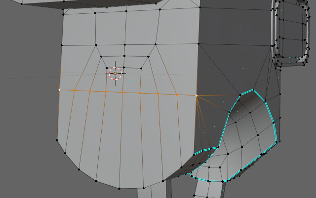
Figure 8.14 – Vertices selected to be pulled to the sides
Figure 8.15 has the vertices pulled to the side.

Figure 8.15 – The plane with vertices pulled to the side
Then, we will pull all of those middle vertices up into the selection in Figure 8.16.

Figure 8.16 – The plane with middle vertices pulled into the selection
Then, all that is left to do is to pull the middle vertices into either the top or the bottom. In this case, it was just whichever was closer. Figure 8.17 shows the final merging of the center vertices.

Figure 8.17 – The plane with middle vertices merged
Now, we can start to deal with the vertices on the edge. For this, we want to make sure we have a good understanding of what each of these vertices is controlling. You can see the vertices in question selected in Figure 8.18.

Figure 8.18 – The selected edge vertices we will work on next
Ideally, we would be able to merge all of these into one of the corners of the faces. Unfortunately, in this instance, it does not appear as though that is a possibility. If we were to merge the vertex at the bottom of this selection into the bottom corner, there would be some overlapping, as shown in Figure 8.19.

Figure 8.19 – Overlapping edges in the bottom corner
That is something we want to avoid, so in this case, it would be wise to keep one vertex on the edge that we can merge all other vertices to, like in Figure 8.20.

Figure 8.20 – A vertex retained on the edge to avoid overlapping
Now, we can take a look at the front and merge the vertices selected in Figure 8.21 to the edges.

Figure 8.21 – Vertices to merge on the front
Next, we just need to extrude the selected vertices in Figure 8.22 to the top and the bottom.

Figure 8.22 – Vertices to be merged to the top and bottom
All that is left to do is to merge the edge vertices in Figure 8.23 to the top or the bottom.

Figure 8.23 – Edge vertices to be merged
In this case, merging them to the bottom kept any edges from getting too squashed or intersecting with each other in Figure 8.24.

Figure 8.24 – Edge vertices after being merged to the bottom
Now, when we look at the selected vertices on the top of the model in Figure 8.25, we can start to merge them together.
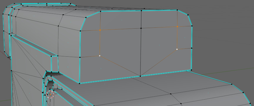
Figure 8.25 – Vertices selected at the top of the model
Figure 8.26 shows the vertices merged into the center.

Figure 8.26 – Vertices after being merged to the center
Then, they are merged into the bottom vertex, as shown in Figure 8.27.
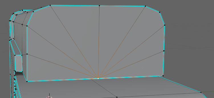
Figure 8.27 – Top vertices merged into the bottom vertex
Then, on the top of the blaster, we will merge the selected edges, as shown in Figure 8.28, into the edges.

Figure 8.28 – Edges to be merged on the top of the blaster
After merging, you should get a result like Figure 8.29.

Figure 8.29 – The top of the blaster after edges have been merged
The shading has become messed up because when we merged the selected edges into the edges that were marked sharp, the sharpness was removed. This is easily remedied by marking the edges again with Ctrl + E, like in Figure 8.30.

Figure 8.30 – The top blaster with edges remarked
Then, moving to the back, we have the vertices selected in Figure 8.31.

Figure 8.31 – Vertices selected at the back
Again, we are going to merge these into the center, like in Figure 8.32.

Figure 8.32 – Vertices at the back that have been merged in the center
Then, merge the remaining vertices into the top and bottom in Figure 8.33.
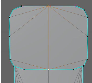
Figure 8.33 – Remaining vertices merged at the top and bottom
Now, we are going to clean up those vertices on the corners that affect multiple parts of the model, selected in Figure 8.34.

Figure 8.34 – Vertices at the corners that need to be merged
Then, as shown in Figure 8.35, we merge the vertices.

Figure 8.35 – Vertices merged at the corners
Now, all that we have left to do is our trigger guard area. To start, we are going to merge this edge into the edge above it, as shown in Figure 8.36.

Figure 8.36 – The selected edge that needs to be merged up
You can see the result in Figure 8.37.

Figure 8.37 – The selected edge after merging
Now, we will look at the vertices selected in Figure 8.38.
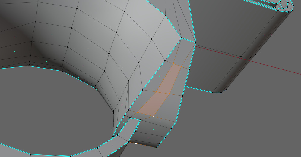
Figure 8.38 – Selected vertices
We then merge them to the left edge, like in Figure 8.39.
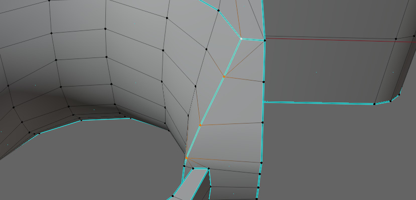
Figure 8.39 – Selected vertices merged to the left corner
To finish this off, we will merge the selected vertex on the corner between the trigger guard and the main body, as shown in Figure 8.40, into the vertex to the right of it.

Figure 8.40 – The vertex to be merged to the right
This is the only vertex on the edge we can merge without affecting the shape of the model. Figure 8.41 shows the vertex after it is merged.

Figure 8.41 – The vertex on the trigger guard after being merged
The left side of the trigger is optimized the same way as this side, so when you are done, the final model should look like Figure 8.42.

Figure 8.42 – The final model of the blaster after the trigger guard is optimized
And with that, our optimization is almost completely done. All of the other sections of the blaster were either curved or had very little to optimize because they were already very flat. Figure 8.43 shows the final model.

Figure 8.43 – The final complete model after optimization
Now, we can compare it to the model before we optimized it. To check the triangle count of the model, click the right mouse button while hovering over the footer at the bottom of your screen. The Status Bar tab should pop up. Select the Scene Statistics option, as shown in Figure 8.44.

Figure 8.44 – The menu to view Scene Statistics
With that, you should be able to see the triangle count, labeled Tris. In this case, our model has 3,290 triangles. Our original mesh had 4,196 triangles. Therefore, almost 1,000 triangles have been removed on just this one model. Figure 8.45 shows the two models together.

Figure 8.45 – A comparison between the unoptimized model (top) and optimized model (bottom)
The top model has substantially more triangles than the bottom one, but there is almost no visual difference between the two. The only major difference is the better performance of the optimized blaster. Now that we know the general workflow on a hard surface, we can try to adapt that to the deforming model that we made previously.
Optimizing deforming meshes
Optimizing a deforming mesh is very similar to working on a hard surface. Like before, the objective is to minimize the triangle count to improve performance. The main difference is that, now, we not only need to make sure not to disturb the shape too much but also ensure we do not affect the way the mesh deforms. That is why our strategy will be very similar. We will modify the areas of detail as little as possible, and also avoid deforming areas as much as possible. So, it is easier to start in areas that we know are not going to deform a whole lot. In this case, we will start with the side of the head shown in Figure 8.46.

Figure 8.46 – A close-up of the side of the head that we will start work on
Like our hard-surface model, we are going to use a vertex slide to merge these vertices into the row next to them. You can see the merged vertices in Figure 8.47.
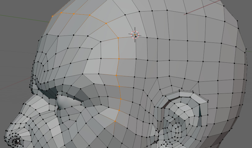
Figure 8.47 – The first row of merged vertices on the side of the head
Then, we will repeat this for the next row to the right of it, which you can see in Figure 8.48.

Figure 8.48 – The second row of merged vertices on the side of the head
Note how there are now two triangles at the base of the merges that we just did. If we take a closer look at Figure 8.49, we can see that this merge also created a pole connecting five edges.

Figure 8.49 – A pole connecting five edges
We want to make sure that when we merge things together, we do not form poles with more than five edges. We are going to continue merging edge loops along the back of the head, starting above the ear, as shown in Figure 8.50.
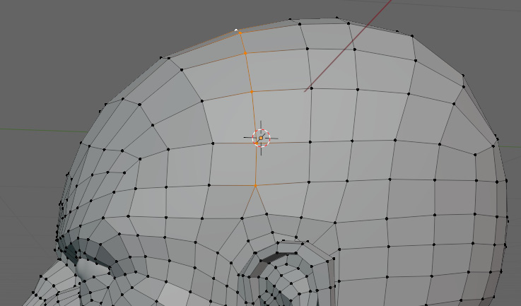
Figure 8.50 – The area above the ear merged
Then, we are going to merge two more at the back of the head in Figure 8.51.

Figure 8.51 – The area at the back of the head merged
Then, we want to look at loops going in the other direction across the head, such as the loop merged in Figure 8.52.

Figure 8.52 – The merged loop at the back of the head
This same merge also wraps around the front face, as shown in Figure 8.53.
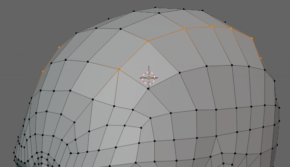
Figure 8.53 – The merged loop from the back of the head also merged at the front
Note how the triangle starts above where most of the animating will be done for the brow. Now, we can start working on the neck. Figure 8.54 shows the merging we are going to be doing across the neck.
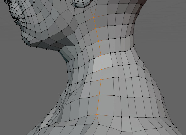
Figure 8.54 – The area on the neck merged
Figure 8.55 shows the topology after merging.

Figure 8.55 – The topology of the neck after merging
All of the triangles are far enough away from the neck to not affect the deformations at all. On the front of the neck, we merged two edge loops together, going all the way from the chin to the bottom of the chest, as shown in Figure 8.56.

Figure 8.56 – Front of the neck after being merged
With that, we can move on to the back. Figure 8.57 shows us the neck, which now looks much better.
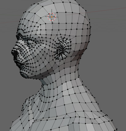
Figure 8.57 – The view of the neck after optimization
The back has one major area at the top around the selected edges, as shown in Figure 8.58, that we need to address.
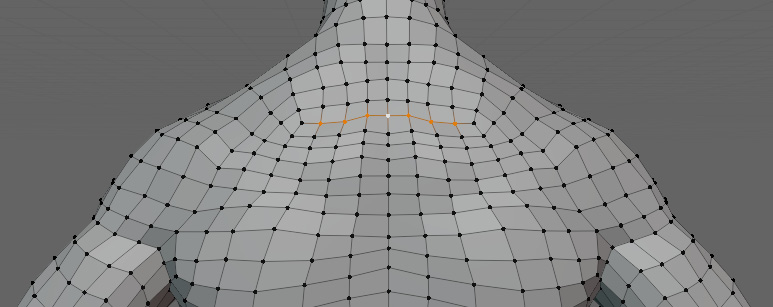
Figure 8.58 – The area on the back that needs to be optimized
We merge this area into three edges, as shown in Figure 8.59.
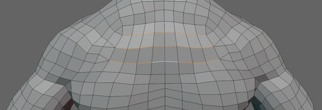
Figure 8.59 – The area on the back after the edges have been merged
After dealing with this, the back looks pretty good, so next, we will move on to the arm. On the arm, we do not want to reduce the number of edge loops going around the arm, as these are most important for twisting and bending deformations on a cylinder-like object such as our arm. We are going to merge edges like those shown in Figure 8.60.

Figure 8.60 – Edges to be merged on the arm
This way, we can put the triangles our merging makes before the wrist and the shoulder. It ends up that every other pair of edge loops can be merged, like Figure 8.61.
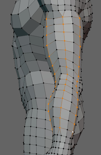
Figure 8.61 – The arm after being merged
Now, we just have to repeat this process on the legs, like in Figure 8.62.
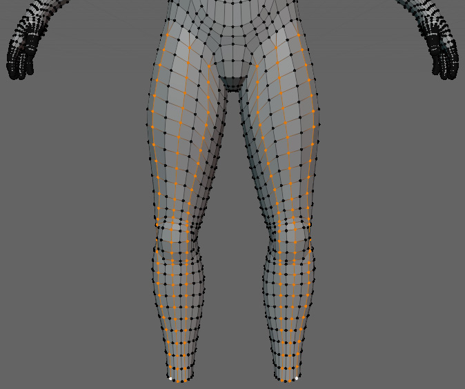
Figure 8.62 – Legs after optimization
And with that, our optimization is done. Figure 8.63 shows the optimized mesh next to the original mesh.

Figure 8.63 – Comparison of the optimized mesh (left) and the original mesh (right)
Again, I think it would be hard to tell which model was optimized and which one was not. The model on the left is the optimized model with 10,240 triangles, and the model on the right is the original mesh at 11,976. That is a change of over 1,700 triangles with just merging a few edge loops. There is definitely room to reduce the triangle count by a few more, but there is a point where you are no longer removing enough triangles to justify the amount of time spent on optimizing. With this model, we have reached a satisfactory point, with relatively little effort.
Summary
In this chapter, we learned why optimizing topology is important. We also explored how to achieve this optimization by using Auto Merge and vertex slide. By now, you should have a good idea of how to optimize hard-surface models and deforming models.
With this, our topology process is complete. Now that we have our optimized meshes, they are ready for rigging, materials, and then finally, whatever medium they are getting used for. From the fundamentals of topology to the retopology of complex hard-surface and deforming meshes, you should be well-equipped to approach them all as you develop your own workflow based on this foundation.