
7
Topology on a Hard Surface
Now that we have some experience with retopology on an organic shape like our monkey man, we can look at topology on a hard surface model. Thankfully, it is not too different from our normal modeling with one major exception: normals on hard surface models are far more important.
We are going to use the same techniques on a hard surface as we did on our organic model. We will start by breaking the model into areas of detail. If the model is already made of multiple parts, this can be a good place to start.
In this chapter, we will be exploring the following subjects:
- Normals on a hard surface
- Retopology of the grip of a blaster
- Retopology of the front shielding
- Retopology of the front grip
- Retopology of the barrel
- Retopology of the main body of the blaster
Normals on a hard surface
As we learned back in Chapter 2, under the Understanding good topology using grids section, the normal is the direction that the faces are facing. One feature we have not talked about yet is smooth shading. The shading shown in Figure 7.1 is what we have experienced so far and this is called flat shading.

Figure 7.1 – A cube with flat shading
Flat shading shows the normals exactly as shown by the geometry. You can see every face individually and each face is separated by a sharp edge. Smooth shading averages the normals of all of the faces to smooth out the edges of intersecting faces. You can see that the shading is set to smooth in Figure 7.2.

Figure 7.2 – Cube with smooth shading
You can change the shading mode of a model by going to the Object tab at the top of the viewport and selecting either Shade Smooth or Shade Flat as shown in Figure 7.3.
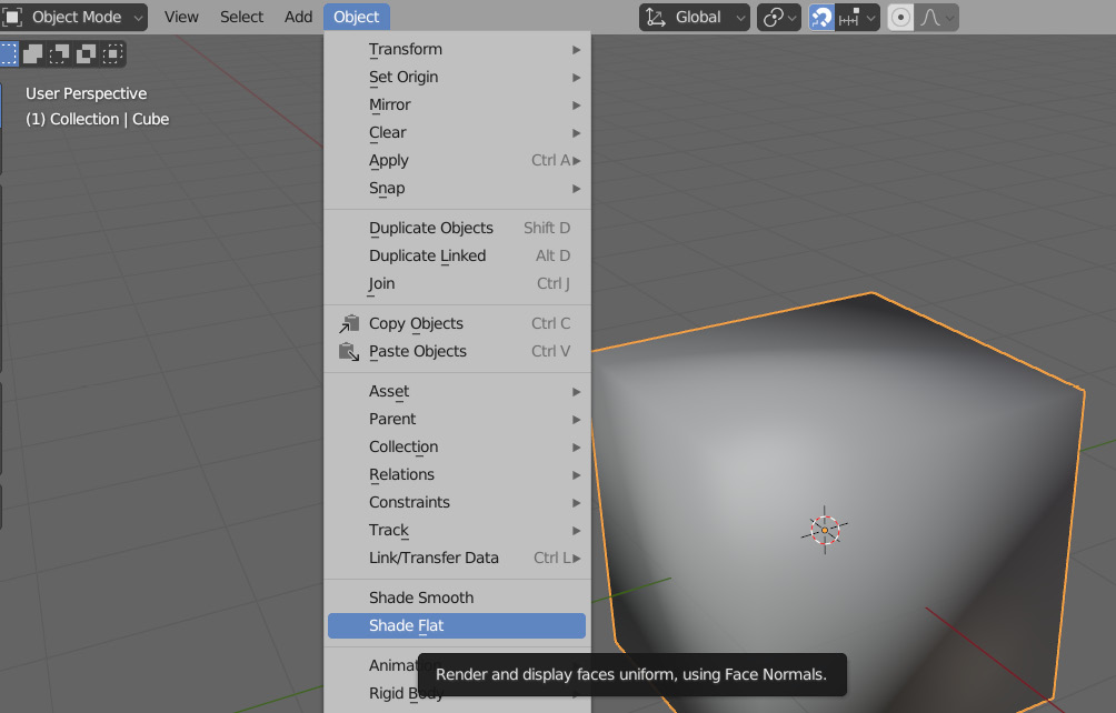
Figure 7.3 – The Object tab with smooth and flat shading options
Notice how it looks just fine on our organically shaped mesh, but as soon as we try and use smooth shading on something that is supposed to have sharp corners, it starts to look a little off. Figure 7.4 shows a cube with smooth shading applied to it.
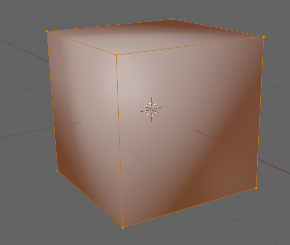
Figure 7.4 – Smooth shading in Edit Mode
As you can see, the shading is now trying to average the normals across a ninety-degree angle. This is causing some severe shading artifacts. Shading artifacts can be anything causing the final surface of the model to look off. In this case, the cause of the artificing is that the shading is having to smooth corners that are too sharp. If we were to add more faces where the edges are by beveling them, then the cube faces will start looking flatter as more levels are added to the bevel, as shown in Figure 7.5.

Figure 7.5 – A beveled cube
To bevel the edges, press Ctrl + B.
The normals are flatter on the main surface because now that there are more faces on the bevel the angle between each of the faces is more gradual, making the smoothing between each face far less extreme. This result can be good for some situations, but if you take a look at the corner close up like in Figure 7.6, the corner is still being smoothed a little too much.

Figure 7.6 – Smoothed beveled edges
A result that may be preferable would be something similar to Figure 7.7.
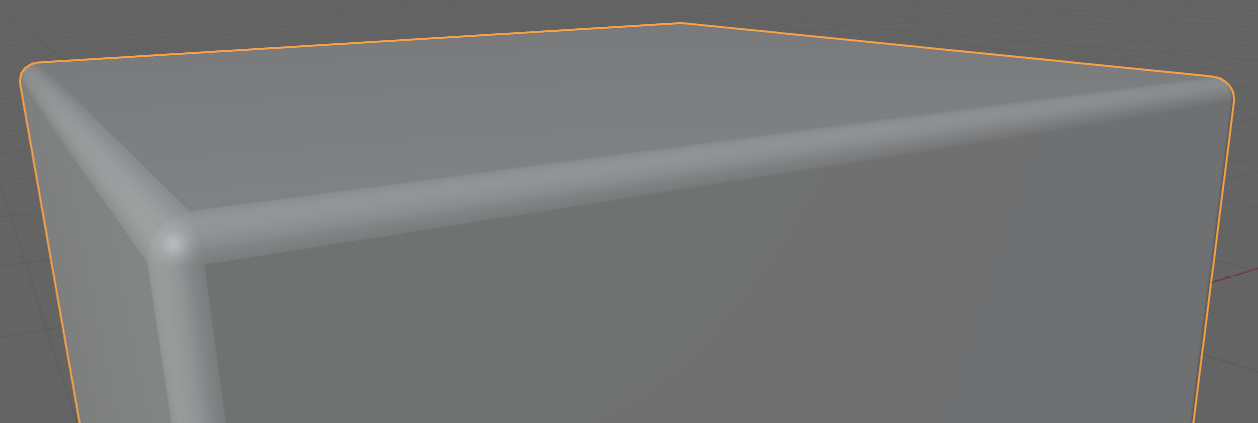
Figure 7.7 – Sharper beveled edges
This sharper bevel is caused by some sort of separation in the normals of the face to keep the edges sharp. There are a few different ways to do this, but we primarily are going to focus on two methods.
Auto Smooth
The first of these methods is by using Auto Smooth. Auto Smooth is a setting that allows you to decide what edges are smoothed based on the angle between their connected faces. The setting can be found in the Normals dropdown in the Object Data Properties tab shown in Figure 7.8.

Figure 7.8 – The Normals tab in the Object Data Properties tab
If we enable this on our smoothed cube in the viewport, you will notice immediately our cube will get its sharp edges back. This is because the angle of all of the edges is 90 degrees and this is above the threshold in the Auto Smooth setting, which is set to 30 degrees by default. You can change this threshold in the Auto Smooth settings shown in Figure 7.9.
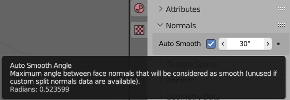
Figure 7.9 – Auto Smooth settings
This method is great if you are not planning on using beveled corners and if all of the corners you want to stay sharp are above the angle threshold. If this is not the case, the second method will allow us to manually mark the edges that we want to be sharp.
Mark Sharp
For this method, we need to go into Edit Mode again. This method also requires Auto Smooth to be enabled. You can set this to any angle you need for most of your edges, or set the threshold to 180 degrees to keep it from sharpening any of the edges. You can see a cube with Auto Smooth set to this in Figure 7.10.

Figure 7.10 – Auto Smooth set to 180 degrees with smooth shading enabled
With Auto Smooth enabled and set to the desired angle, we can start manually marking the edges we want to sharpen in Edit Mode. To mark an edge as sharp, you need to do the following:
- Select the edge you want to sharpen.
- Press Ctrl + E to open the Edge menu.
- Select the Mark Sharp option on the dropdown shown in Figure 7.11.
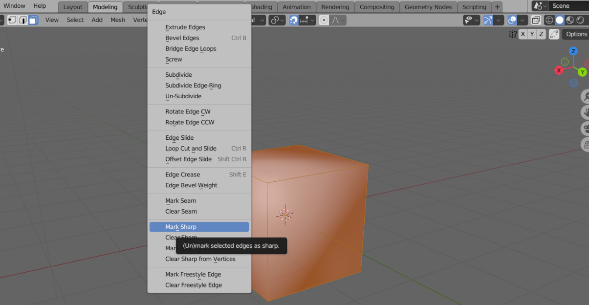
Figure 7.11 – The Edge menu
After marking the edge as sharp, there should be a blue highlight on the marked edge as in Figure 7.12.
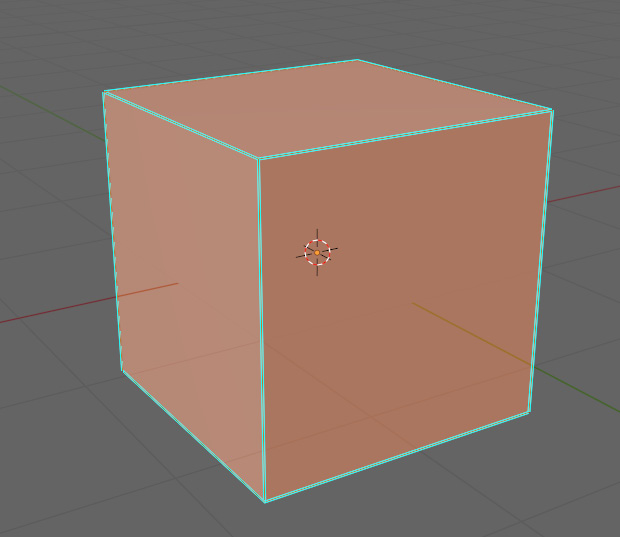
Figure 7.12 – Edges marked as sharp
Knowing how to mark our edges as sharp will make it much easier to visualize how our topology looks when retopologizing. With this new knowledge regarding normals, we are ready to start looking at the retopology of a hard surface model.
Retopology of the grip of a blaster
To practice topology on a hard surface model, we are going to be retopologizing the blaster shown in Figure 7.13.
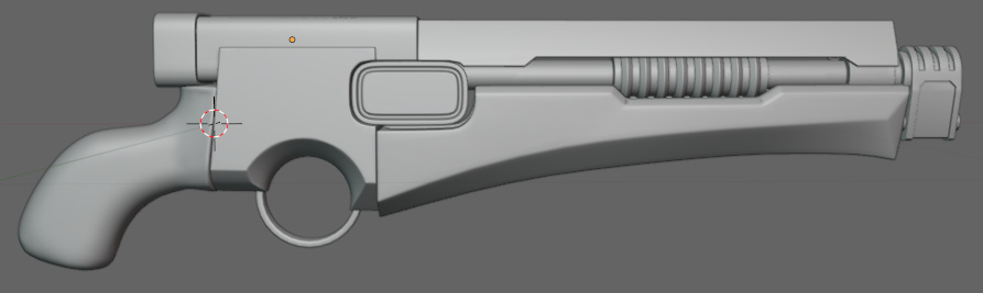
Figure 7.13 – The blaster
Like our previous methods, when we start, we want to break the model down into segments. In this case, we are going to start with the grip. Figure 7.14 gives us a closer look at the grip.

Figure 7.14 – The grip of the blaster
To start the retopology, we are going to snap a separate mesh onto the grip. Just like in our previous models, we are going to start by outlining the model with guiding vertices. First, we will put vertices on any creases or sharp edges. You can see an example of this in Figure 7.15.
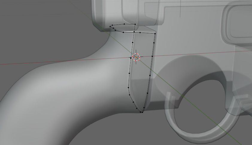
Figure 7.15 – Vertices placed on the edges of the grip
Next, because the grip is rather cylindrical, we are going to define the loops of the grip in a few increments as we did on the arms and fingers of our character. For this model, we ended up doing three loops as well as the loops of vertices that we already did around the edges at the top. Figure 7.16 shows these loops.

Figure 7.16 – Guiding edges on the grip
These loops do not need a lot of detail because we are going to use a shrinkwrap modifier to help us fill in any areas later. These loops are just there to get the flow of the topology right for the next step. Our next step is to join those simple loops together to get something like Figure 7.17.
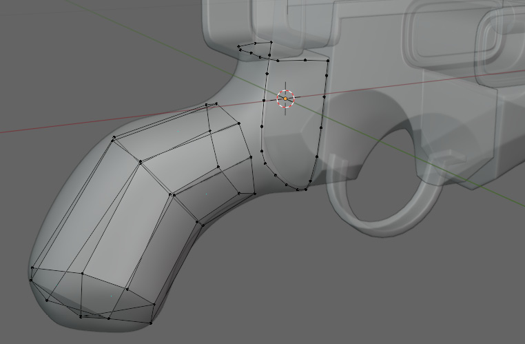
Figure 7.17 – Guiding edges filled in with faces
Now, we have a problem at the top of our grip. There are far more vertices on the right in Figure 7.18 than there are on the left.
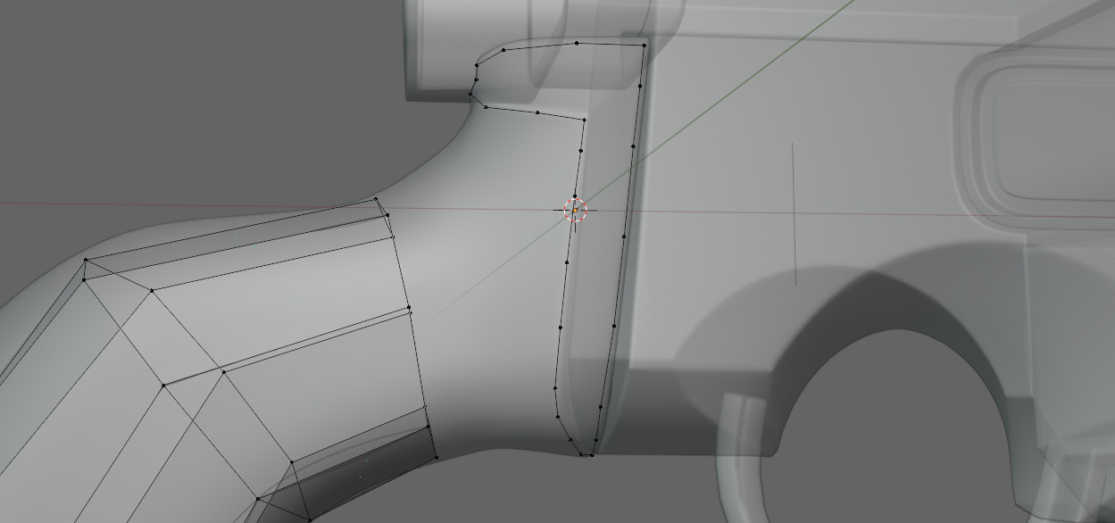
Figure 7.18 – More vertices on the right of the mesh and fewer on the left
To address this, we are going to start by extruding the vertices on the end into something similar to Figure 7.19.
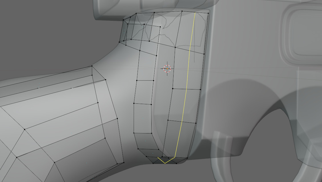
Figure 7.19 – Extruded vertices from the edge
Make sure that the edge loops going through these faces intersect like a normal grid. This is because we are trying to move the pole selected in Figure 7.20 closer to the faces we need to connect it to in order to prevent stretching.

Figure 7.20 – Pole that will have five edges
With this pole now moved closer, we can loop cut the mesh on the left side to make it match with the right. Do not worry too much about snapping at the moment. When you have all of the vertices matching up on either side, you can finally connect it like in Figure 7.21.

Figure 7.21 – The Left and right meshes joined with faces
Now, we can add loops to even out the topology. To add more than one loop, just do a normal loop cut with Ctrl + R, then scroll up on the mouse wheel. Then, we can apply a shrink wrap modifier in the modifier tab. On the shrink wrap modifier, make the target the object you are snapping to. Now, just apply the modifier. After the loop cuts and shrink wrap, it should look like Figure 7.22.

Figure 7.22 – Finished grip
With that, our grip is done. We can now start on the next part of our blaster, which is the front shielding.
Retopology of the front shielding
The next section we are working on is up at the front of the blaster. It is the angled plate that sits above the barrel illustrated in Figure 7.23.
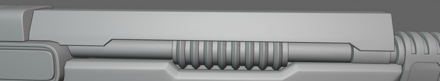
Figure 7.23 – The front shielding
Like we did on the grip, we are going to start by outlining the edges of the model. In this case, it is rather easy, as the shape is relatively simple. You can see the outline in Figure 7.24.
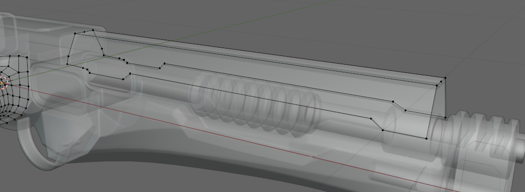
Figure 7.24 – Edges outlined with vertices
The important thing to think about in this case is how we are going to make the faces of the front shielding that are seen in Figure 7.25.
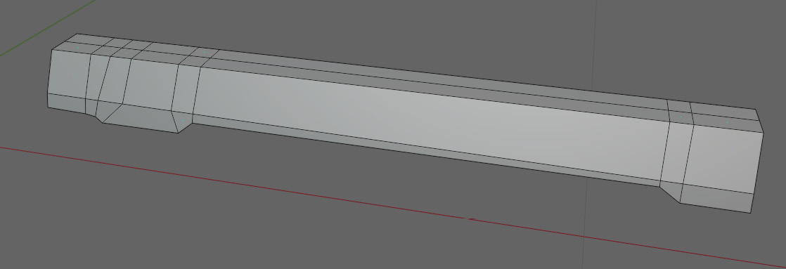
Figure 7.25 – Outlined vertices joined with faces
Here is the model after connecting all of the faces on it. This is the part of a deforming model where you would add more loop cuts in the middle to give it a consistent grid density. On a hard surface, however, there is no need to add more geometry because the model is not going to be deforming. All we have to worry about is the shading when we enable smooth shading. Figure 7.26 shows us the model with smooth shading enabled.
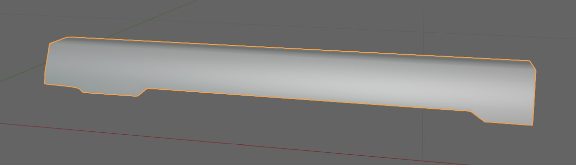
Figure 7.26 – The mesh with smooth shading applied
Now with smooth shading on, we cannot make out any of the edges of our model. The first thing when addressing this issue is to turn Auto Smooth on. For this model, we have a few curves that need to be smoothed, such as on the grip, and some subtle edges that need to be sharp. This means we cannot rely on Auto Smooth alone to get the desired shading. In this case, we are going to set the Auto Smooth angle to 60 degrees. This is a good threshold that usually sharpens only the edges that we want to sharpen. For the edges with an angle less than 60 degrees, we will have to mark them as sharp manually. Figure 7.27 shows the model with Auto Smooth enabled and set to 60 degrees.

Figure 7.27 – The mesh with Auto Smooth set to 60 degrees.
This is a good improvement but there is still one small edge on the side of the shielding that we need to sharpen. To achieve this, go through the following steps:
- Go into Edit Mode.
- Select the edge you want to mark.
- Press Ctrl + E to bring up the Edge menu.
- Then, select Mark Sharp.
With the edges marked sharp, our model looks like Figure 7.28.
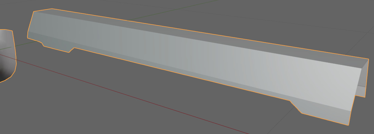
Figure 7.28 – Mesh with edges marked sharp
Now, all that we have to do is add some thickness to the shield. To do this, we just have to extrude the edges around the shield and snap them in place. You can see an example of this in Figure 7.29.
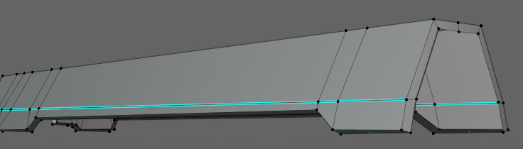
Figure 7.29 – Sharp edges in Edit Mode
With that, our shielding is done and we can move on to the next segment of our blaster, the front grip.
Retopology of the front grip
The next part of the blaster we are going to look at is the front grip. Figure 7.30 shows a close-up of the front grip.
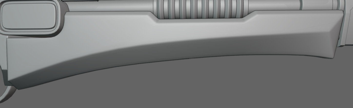
Figure 7.30 – The front grip
Again, we are going to lay out the lines on our edges and corners first. You can see the guiding edges in Figure 7.31.
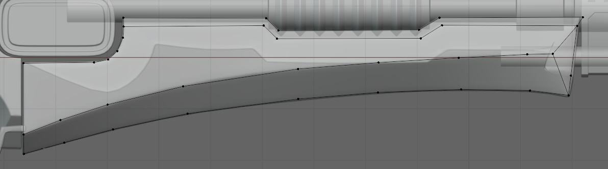
Figure 7.31 – Guiding edges
Next, we are going to start making the faces of the front grip. Most of the faces are going to be easy to place, but we should focus on the radius at the top left of the grip. You can see that there are far more vertices on the radius than the surrounding mesh. To address this, we just need to send the loops around the bottom of the grip. Figure 7.32 shows the finished faces.
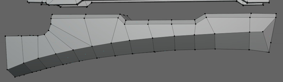
Figure 7.32 – Guiding edges joined with faces
After adding new geometry, you may need to smooth the model again. The smoothed faces can be seen in Figure 7.33.
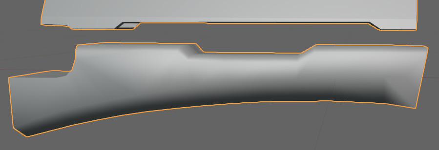
Figure 7.33 – Smooth shading applied
You can see that the auto-smoothing did not do as much as it did on the previous models, so this means we need to do a bit more manual edge marking. Figure 7.34 illustrates the model after the edges have been marked.

Figure 7.34 – Edges manually marked sharp
With that, the front grip is done and we can move on to the barrel of the blaster.
Retopology of the barrel
For the barrel, it will be helpful for us to hide the sections of the blaster that are obscuring it. To do this, simply select all of the parts of the model that you want to hide in Edit Mode, then press H. This will hide all of those parts of the mesh in Edit Mode only. To unhide them, just press Alt + H. In Figure 7.35, the barrel is exposed while all of the other pieces of the blaster are hidden.

Figure 7.35 – The exposed barrel
This section is going to be our most difficult yet, as it has some small details with a lot of interacting shapes. It is important not to get overwhelmed and to just break it down into separate detailed areas that we can approach one at a time. In this case, the top of the front of the blaster in Figure 7.36 appears to be the most detailed area, so we are going to start there.

Figure 7.36 – The most detailed area on the barrel
We will approach this section, just like we have done in all of the previous sections, by outlining the edges and creases. Figure 7.37 has all of these guiding edges in place.

Figure 7.37 – Guiding edges on the top of the blaster front
After filling all of the faces of these edges, it should look something like Figure 7.38.

Figure 7.38 – The faces connecting the guiding edges
Now, we can move a little bit lower down to work on the indented shape in Figure 7.39.
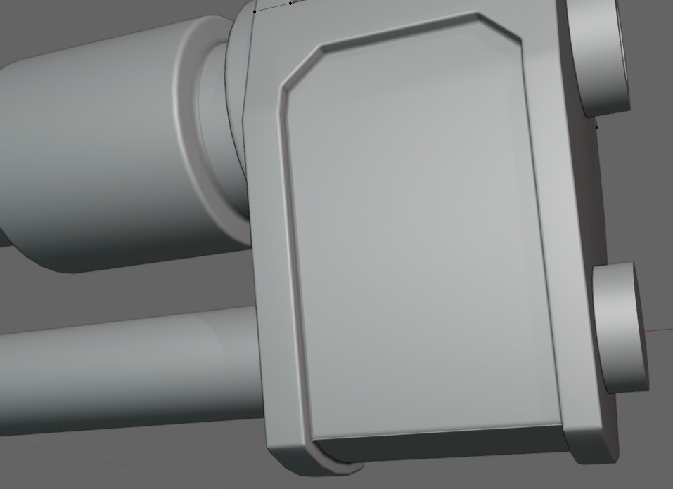
Figure 7.39 – Lower detailed area
Again, we are going to begin by adding edges in the creases and edges. After outlining this shape, it should look like Figure 7.40.

Figure 7.40 – Guiding edges on the lower part of the blaster
After we make our faces connect to everything, it should look like Figure 7.41.
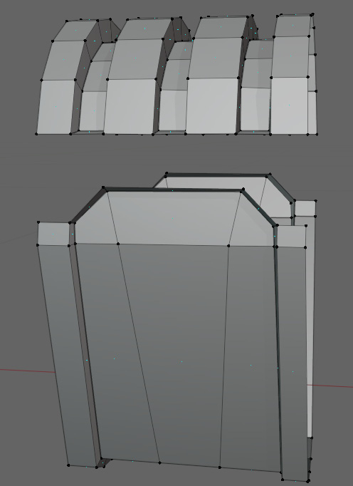
Figure 7.41 – Guiding edges filled with faces
Now, we just need to add loops to the bottom part so that it matches the top and we can connect the top and bottom of the barrel. Figure 7.42 shows the two sections joined together.

Figure 7.42 – Top and bottom joined
Now, we can add cylinders around the pipes that intersect the shape we just modeled. You can add a cylinder with Ctrl + A, or you can manually snap vertices around them. Figure 7.43 shows the added cylinders.
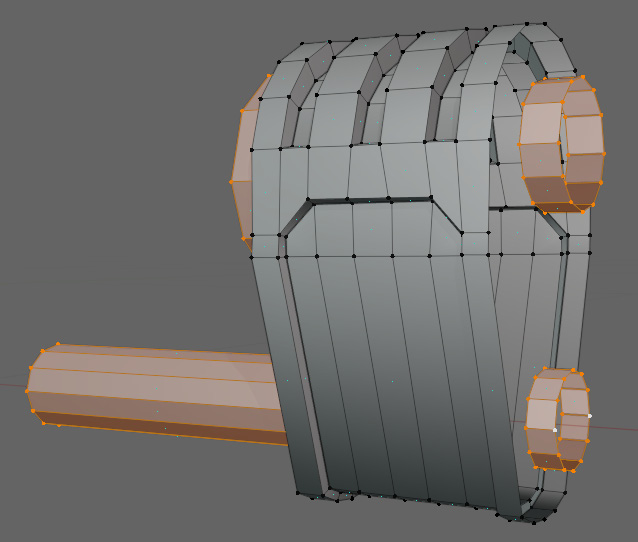
Figure 7.43 – The added barrel cylinders
Notice that the cylinders are not attached yet and this attachment is, unfortunately, quite difficult to achieve. Because the top is cylindrical and the barrel is also cylindrical, this is a good place to start. Figure 7.44 shows these two sections connected after dissolving some of the edges to get them to match up.

Figure 7.44 – Connecting the cylinder to the top
Next, we can join the top to the bottom like in Figure 7.45.

Figure 7.45 – Connecting the cylinders to each other and the bottom
We are trying to reduce the number of exposed faces on our cylinders with all of the edges we have available so that we can add as few loop cuts as possible to what we have already made. In Figure 7.46, we added a loop to the faces, bridging the two cylinders together, and then connected those faces to the main piece.
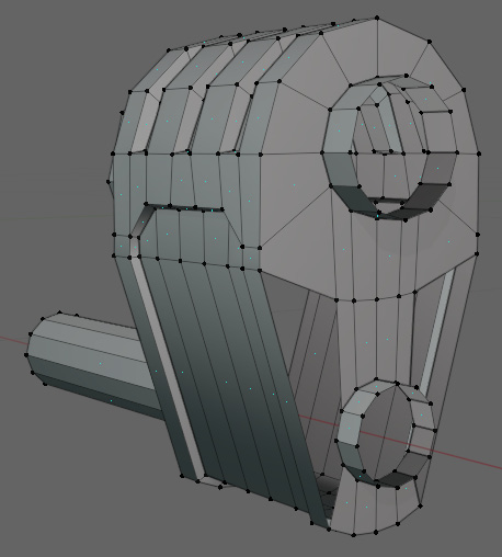
Figure 7.46 – Filling in the sides
This leaves us only needing two loops on the long faces to connect them to the bottom cylinder. The final connection is in Figure 7.47.

Figure 7.47 – The filled faces with the added loop cuts
After we repeat this on the backside, all that is left to finish is the barrel. Thankfully this is not too difficult to do. All we have to do is apply the mirror modifier, then extrude and scale the barrel for each step. This will be a little painful, especially at the center of the barrel with all of the ridges, but when it is done it should look like Figure 7.48.
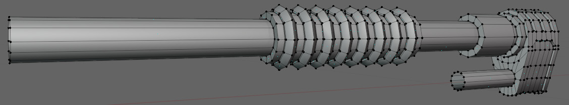
Figure 7.48 – Finished barrel
Now, we can unhide the rest of our mesh and see how well Auto Smooth worked, as shown in Figure 7.49.

Figure 7.49 – The finished front portion of the blaster
It looks like Auto Smooth was able to take care of everything here because all of the edges were so sharp. So, now we can move on to the final part of the blaster, the main body.
Retopology of the main body of the blaster
Finally, we can start working on the main body of the blaster. You can get a closer look at it, with all of the other bits hidden, in Figure 7.50.

Figure 7.50 – The main body of the blaster
Figure 7.51 has all of our guiding lines drawn out for the large middle piece.
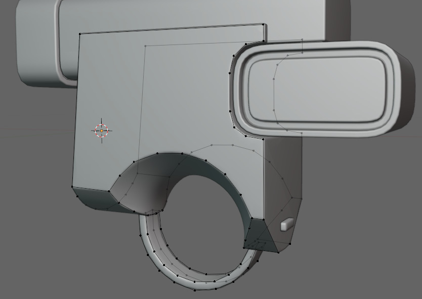
Figure 7.51 – The guiding lines on the large middle piece
Figure 7.52 shows the edges filled in with faces.

Figure 7.52 – The large middle piece filled in with faces
Now, we just repeat the same steps for the last two parts of the blaster and we are finished. Figure 7.53 shows the final middle piece.

Figure 7.53 – The finished body
With that, our blaster is complete. Figure 5.54 shows the finished blaster.

Figure 7.54 – The finished blaster
Summary
In this chapter, we learned how smooth normals work and how to use Auto Smooth. You should now also know how to mark edges as sharp and how to retopologize a hard surface object.
Finally, with this chapter done, we should be comfortable using the topology rules that we introduced in the first part of the book. Up until this point, we have exclusively used a quad-based workflow, only using faces that have four vertices and edges. In the next chapter, we are going to explore the use of triangles to reduce the total number of faces on a model.