4
Improving Topology Using UV Maps
With the basics of topology and how it deforms taken care of, there is one last consideration to be made when laying out the topology of a model. That last consideration is how the material is going to be applied to it. There are a few ways to do this, but the most consistent way of doing this is by UV unwrapping and applying image textures to the surface of the model.
This chapter will start by introducing you to a UV map, and then we will move on to explaining how it works. Once we have an understanding of the UV map itself, we will move on to its relationship to the topology of the model. Then, we will learn how to check a model’s UV map and improve it.
In this chapter, we will be learning about the following subjects:
- What is a UV map?
- Ensuring clean topology for clean UV maps
- Unwrapping the mesh
- Improving unwraps
What is a UV map?
To start out, what is a UV map? A UV map is a 2D representation of a 3D mesh. It is where you take all of the faces of your mesh and flatten them out. In Figure 4.1, you can see a cube next to its UV map:
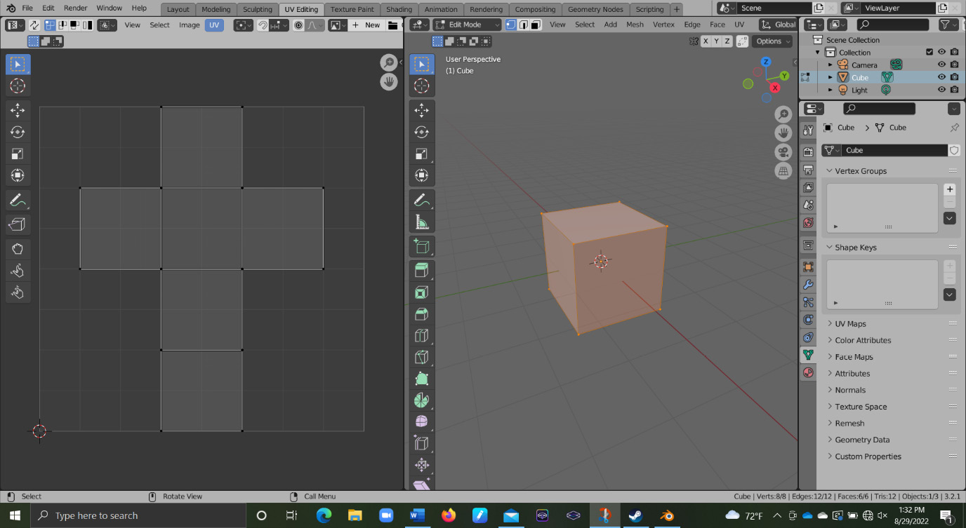
Figure 4.1 – UV map of a 3D cube
To view your UV map, it is easiest to navigate to a different workspace at the top of your screen. The workspace you are looking for is the UV Editing workspace. You can see this workspace in Figure 4.2:

Figure 4.2 – UV Editing workspace
Now that we are in the UV Editing workspace, your screen should match the layout of Figure 4.1. To see your UV map on the left, go through the following steps:
- Select the object in Object Mode.
- Then switch to Edit Mode.
- And finally, press A to select all of the faces of the model.
By default, you can only edit the UVs of faces that you have selected.
With all of the faces selected, you should now see your UV map on the left. You can now select any of the edges, vertices, or faces on your UV map to modify it. All of the same transform hotkeys that you use in the viewport also apply here: G to move, S to scale, and R to rotate. Figure 4.3 shows a vertex on the UV being moved:

Figure 4.3 – Editing the UV faces
You may have also noticed that navigation in this area is also similar to the viewport. Use the MMB to pan and scroll up and down on the mouse wheel to zoom in and out.
At the moment, it is difficult to tell how our model is being affected by modifying our UV map, so we are going to add a simple material. That way, we will easily be able to see how our UV relates to our mesh. First, we will press the tab labeled Image in the UV Editing area, as shown in Figure 4.4:
Figure 4.4 – Image tab in UV editor
In that dropdown, select New. After you select New, a tab will open showing you the parameters of the image you want to create. The part we want to focus on is the Generated Type option. This allows us to choose from some preset images called textures that we can use for UV mapping. The selection we want to choose is the Color Grid option from the dropdown shown in Figure 4.5:

Figure 4.5 – Choosing the Color Grid option for the new image texture
With this setting change, we can click on OK at the bottom of the New Image tab and finalize our image texture. At the moment, we have only created the image texture in Blender, and we need to save it to our computer. To save the image, navigate back to the same Image tab we pressed to create the texture. Now that we actually have an image in the UV editor, we have a few more options. In the Image dropdown, select the Save As… option, as shown in Figure 4.6:

Figure 4.6 – The Save As… option
With the image made and saved, we need to apply it to the model by assigning it to the material of the model in the Shader Editor.
Applying a texture
To easily switch to the proper editor, we will use another workspace. To modify materials, we are going to use the Shading workspace shown in Figure 4.7:

Figure 4.7 – The Shading workspace
At the bottom of the Shading workspace, we have the main editor type called the Shader Editor. The Shader Editor allows you to modify the materials of an object. A Material is a set of parameters that determine how your model interacts with light. The individual processes are contained in nodes, and the main nodes that determine how you want your material to look are called shaders. In Figure 4.8, you can see two nodes next to each other in the Shader Editor:

Figure 4.8 – The Shader Editor
The node on the left is the shader node, called Principled BSDF, and on the right, we have Material Output. Principled BSDF is a shader node with the general settings you would have to set for most materials inspired by a similar workflow used by Pixar.
The Material Output node determines what is actually being displayed on the surface of the model. If your shader node is not plugged into Material Output, it will not appear on the model. With that short description out of the way, we can add our image to the material. Before we can actually add it to the material, we need to bring it into the Shader Editor. To do this, follow these steps:
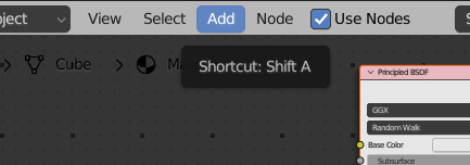
Figure 4.9 – Add option
- In this dropdown, hover over the Texture option, and then click on the Image Texture option. Figure 4.10 shows you what this should look like:

Figure 4.10 – Image Texture option
- As soon as we select Image Texture from the menu, a new Image Texture node will appear in our Shader Editor. You’ll notice that the node is following your mouse. To finalize its position, press LMB when you are satisfied with its placement. To move it again, just like in our viewport and UV editor, select the image texture node with LMB and press G.
- With our texture node in the Shader Editor, we need to assign our texture to it. To do this, simply click on the image icon on our Image Texture node, as shown in Figure 4.11:

Figure 4.11 – Assigning a texture to the node
- Finally, all that is left to do is plug our texture into the shader. To connect our nodes together, press and hold LMB on the yellow circle on the right side of our texture node, as shown in Figure 4.12:

Figure 4.12 – Yellow color output
- When we move our mouse around now with LMB held down, we get a line, as shown in Figure 4.13:
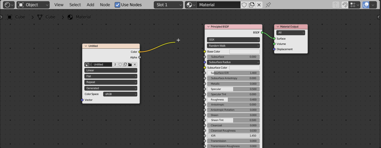
Figure 4.13 – Plugging the texture
All we need to do now is drag that line over to the Base Color input on the Principled BSDF shader node, and release LMB. Now, you should have a line going from the Color output of the Image Texture node, going into the Base Color input of the Principled BSDF node. We can see this connection in Figure 4.14:
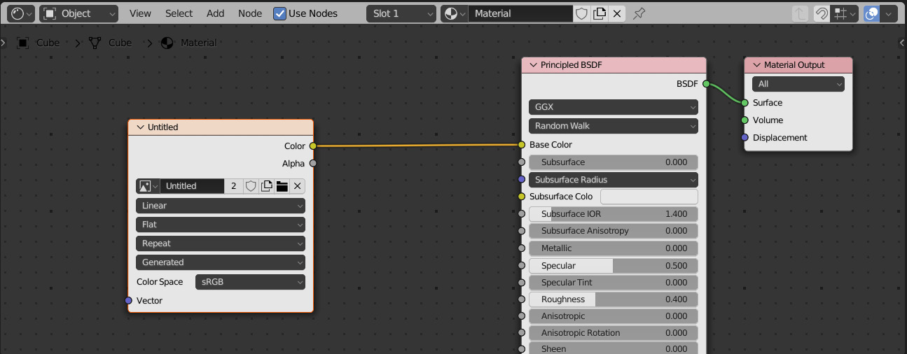
Figure 4.14 – Successful connection of the Color node to the Principle BSDF node
With our texture finally connected to our material, we should be able to see it on our model in our viewport.
Shading modes
If your cube and background still look gray, that is because you need to change your Viewport shading mode. The Viewport shading mode determines how your models appear in the viewport. You can see the four shading mode selections on the top right of the viewport in Figure 4.15:
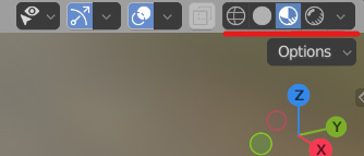
Figure 4.15 – Viewport shading modes
The leftmost option is the Wireframe shading mode. The Wireframe shading mode shows an outline of all of the mesh edges, but not the faces, allowing you to see through the mesh. If we look at our cube in Wireframe shading mode, we will see an effect similar to that in Figure 4.16:

Figure 4.16 – Wireframe shading mode
The next one to the right of the Wireframe shading mode is the Solid shading mode. The Solid shading mode is the shading mode we have been using up until this point. It gives us a solid color with basic shading to view the contours of the model.
The next shading mode to the right of the Solid shading mode is the Material Preview shading mode. The Material Preview shading mode uses the EEVEE rendering engine to add a quick lighting effect to preview materials, just as the name suggests. By default, it switches to Material Preview when you enter the shading workspace. You can see the Material Preview shading mode in Figure 4.17:

Figure 4.17 – Material Preview shading mode
The last shading mode on the far right is the Rendered shading mode. The Rendered shading mode uses whatever rendering engine you have selected to render the viewport. By default, the real-time rendering engine, EEVEE, is selected, but you can change this to Cycles, Blender’s ray-tracing engine, as well. You can see the Rendered shading mode in action in Figure 4.18:

Figure 4.18 – Rendered shading mode
Now, all we need to do is see how our texture is affected by changing our UV map; we will go back to Material Preview.
To quickly switch between the shading modes, press and hold Z until the pie menu in Figure 4.19 pops up:

Figure 4.19 – Switching between shading modes
We can move our mouse around to select one of these, and once we have our desired view selected, all we have to do is release the Z key.
Manipulating the UV map
With our texture applied, and the ability to view it, we can start messing with our UV map. First, we are going to go back into the UV Editing workspace at the top of our screen. Now, we can hold down Z to select our Material Preview shading mode. Next, we want to press these opposing arrows at the top left of our UV editor area shown in Figure 4.19, called UV Sync Selection:

Figure 4.20 – UV Sync Selection
Before enabling this setting, we needed the entire mesh selected in Edit Mode to see the whole UV map, but now we can see the map without selecting the mesh, though we still need to be in Edit Mode.
This also syncs our selections between our UV editor and our viewport. Now, If I select a vertex on the UV editor, its corresponding vertex on the mesh is selected. You can see this selection in Figure 4.21:
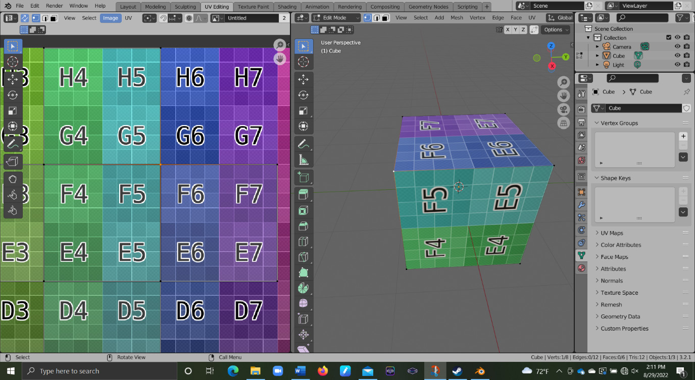
Figure 4.21 – Synced selections
You will also notice that if you select specific individual vertices in the viewport, multiple vertices are selected in the UV editor. That is because these vertices fall on edges that are split in order to flatten out the mesh, so the selected vertices in the UV editor share a vertex in the 3D Viewport. This is illustrated in Figure 4.22.

Figure 4.22 – One selected vertex in the 3D Viewport selecting two in the UV Editor
All of the vertices on the UV map represent the same vertex on the mesh. By selecting the vertex in the viewport, it will select all of the corresponding vertices in the UV editor. To avoid this behavior, we just have to deselect the icon in the top left with the opposing arrows shown in Figure 4.23 and select the whole mesh again.
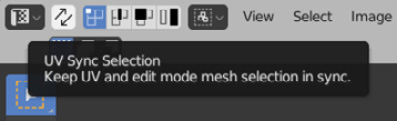
Figure 4.23 – UV Sync Selection icon
If we move one of the vertices in the UV editor, you can see that it changes the way the texture is laid out on our cube. You can see this in Figure 4.24:

Figure 4.24 – Deselection
The faces in the UV editor have a one-to-one relationship with the faces on the mesh, so if we warp our faces in the editor, it will warp how the texture is displayed on the mesh. You can also select the whole UV map and move it around to see how the two are related.
Now, we know how to add an image texture, how to apply that texture to a model using the Shader Editor, how to see that texture on the model by changing the shading mode, how to apply the UV Sync option, and understand how moving vertices in the UV map changes the way the texture is displayed on the model. With this understanding of the basics of a UV map, we can start looking at how we should set up our topology to make manipulating this UV map as easy as possible.
Ensuring clean topology for clean UV maps
Thankfully, there is not too much more we need to think about when laying out our topology for UV maps so long as we have followed our other topology rules. So first, we will look at the rules that apply to UV mapping most. One of the more painful topology issues to work around is when the topology is not flowing with the geometry properly. In Figure 4.25, I have two planes that I want to unwrap:

Figure 4.25 – Planes for unwrapping
The one on the left has jagged edges going left to right, and the plane on the right has straight edges like a normal grid. If we split these in half and look at them in the UV editor in Figure 4.26, you can see how the jagged edges intersect our texture at awkward angles:

Figure 4.26 – Jagged UV map (left), straight UV map (right)
If we wanted the grid pattern to line up perfectly with our plane, we would not be able to use a jagged pattern like the plane. This is specifically an issue if you are setting up your textures to work with a tiling texture, where you need your UV map to unwrap into a perfect plane.
As the name might suggest, a tileable texture is an image texture that can be laid next to itself like a tile floor without having any visible seams between its tiles. You can see an example of a tileable texture in Figure 4.27:

Figure 4.27 – Tileable texture
While you may be able to see the texture repeating, the edges all blend into themselves. In Figure 4.28, you can see the texture applied to our planes:

Figure 4.28 – Applied texture on the planes
The plane with the straight UV map can be manipulated to tile seamlessly, but the jagged one cannot.
When using tileable textures, we want to try to avoid these messed-up edges as much as possible. Unfortunately, it is not always avoidable. In these instances, you want to try to minimize the effect it has on the final model. Like the topology rule that says that the topology should follow the geometry, the rule that says that loops need to terminate into themselves is just as important.
Both of these rules are very easy to spot when UV unwrapping because they will affect the textures immediately. In Figure 4.29, you can see a cylinder that is connected at an offset, so the faces and UV map do not line up with each other:
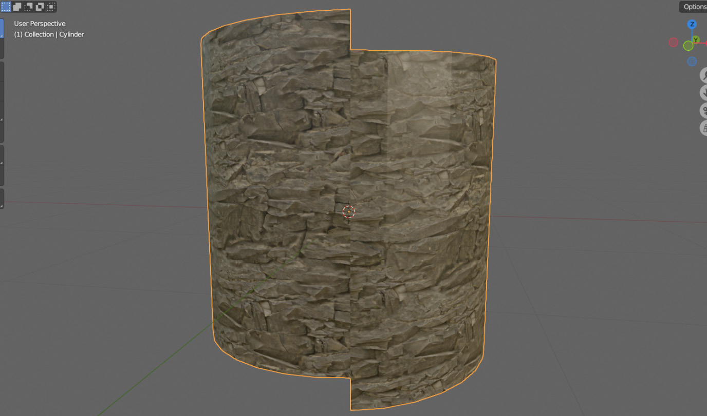
Figure 4.29 – Misaligned unwrapped texture
If we look at our mesh and UV map, it is easy to tell that the texture is not lining up with itself and that the texture actually spirals around the mesh as well. We could try to make the texture line up in the UV editor, as in Figure 4.30:

Figure 4.30 – Lining up the texture
This way, we would even be able to tile the texture without any seams. Unfortunately, this warps the texture because we are forced to stretch our UV map to match up the edges. When a face mismatch like this takes place in a more complex model, it is unlikely that we would even be able to get it to line up. When looking at simple shapes like this, it is easy to understand how and where to split the mesh when flattening it out, but real shapes often have more complex shapes that you need to flatten out. To do this, we need to lay out our topology for unwrapping, which we will see in the next section.
Unwrapping the mesh
Now that we understand a little bit about what UV maps are, and why getting them right is important, we can learn how to actually unwrap a mesh. To unwrap a mesh, we start by marking the edges we want to split our mesh along. To do this, follow these steps:
- Start by selecting the edge we want to split. Next, press Ctrl + E to open up the Edge menu and select Mark Seam from the dropdown, as shown in Figure 4.31:

Figure 4.31 – Mark Seam option
After marking the seam, a red line should appear along the selected edge, as in Figure 4.32:

Figure 4.32 – Marked seam for unwrapping
- This seam shows where our model will split when unwrapping. To unwrap, we start by selecting our whole mesh with A. With everything selected, we can press U. This brings up the UV Mapping tab, as shown in Figure 4.33:

Figure 4.33 – UV Mapping tab
This is the menu that allows us to decide how we want to unwrap our mesh. When manually marking and unwrapping our mesh, just pressing Unwrap at the top of the dropdown is what we want to do. After we unwrap our mesh, we can see it in the UV editor and viewport in Figure 4.34:

Figure 4.34 – Unwrapped mesh
You will notice in our viewport that we still have our red line indicating where we marked our mesh, and in the UV editor, we have two sections indicating the split. Next, we are going to look at a more complex mesh and see how we would approach unwrapping that. A good rule of thumb to start with is to keep our seams on corners, creases, or the intersections of grids.
Our two major objectives when unwrapping are to hide seams and reduce warping when unwrapping to 2D. You will likely recognize the model in Figure 4.35, as we have used this shape a few times now:

Figure 4.35 – A complex model being used for unwrapping
This is going to be the model we will try to unwrap for the first time. To start, we are going to look at that first rule and unwrap where the two grids intersect. If we look at Figure 4.36, we can see where the grid from the T shape and the cylinder of the leg intersect:

Figure 4.36 – Selected edges at the intersection of the leg and hip
While this is where the two grids intersect, we are not actually going to put our seam right on this intersection. That is because there is not a good crease or corner at that intersection to actually put our seam to try and blend it in. So instead, we are going to move our seam to the actual joint of the two shapes. As a recap, to mark the seam, we should go through the following steps:
- Select our seams in Edit Mode.
- Press Ctrl + E to open up the Edge menu.
- Navigate down to the Mark Seam option.
- After selecting that, the Edge menu should close and you should have seams as shown in Figure 4.37:

Figure 4.37 – Seams added to the model
With our seams in place, we can now try to unwrap our mesh for the first time. To UV unwrap the mesh, follow these steps:
- Select the whole mesh in Edit Mode.
- Press U to open up the Unwrap menu.
- Select Unwrap from the top of the list.
With our mesh unwrapped, it should look like Figure 4.38:

Figure 4.38 – Unwrapped mesh for our model
You will notice that the unwrap is severely warping our mesh even though we unwrapped around the intersections of the grids. That is because after separating our grids, we still need to unwrap those individual grids so that they will unwrap as close to a normal flat grid as possible.
To start with, we can use the UV editor to help us mark seams. To do this, make sure you have the UV Sync Selection option enabled, as in Figure 4.39:

Figure 4.39 – Enabling the UV Sync Selection option
This is the option that syncs selections between the viewport and UV editor. This makes it a bit easier to see what edges we are selecting to get marked. In the UV Editing tab, select one of the loops along each of the legs that we separated with our last seams. Make sure that these seams are matching on either side. We are also going to try and hide them as much as possible, so we can tuck them on the inside so that they are harder to see. Figure 4.40 shows what this selection looks like in the viewport and the UV editor.

Figure 4.40 – Selected seams in the UV editor
With our edges selected, we can press Ctrl + E and mark our seams and then unwrap with U. Now, our legs should be nicely unwrapped into normal grids, and our pattern hardly looks warped on the legs. Next, we need to do the T section in the middle. To get this to play flat, we are going to have to mark at least two of the three connections forming the shape. In Figure 4.41, you can see one of these selections.
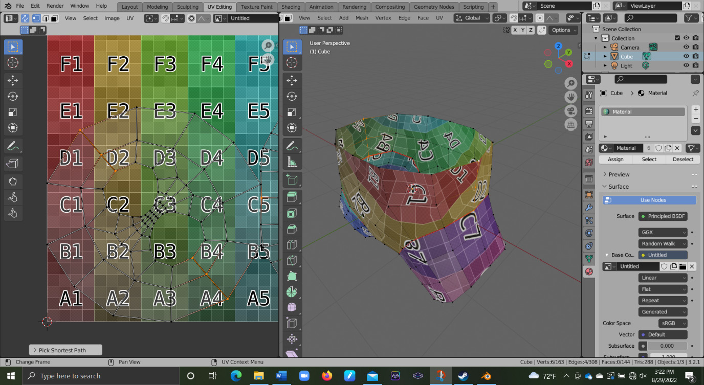
Figure 4.41 – Marking two connections
Again, we are going to mark our seams with Ctrl + E, then unwrap the mesh with U. With our mesh unwrapped using these new seams, we can see the final unwrap in Figure 4.42.
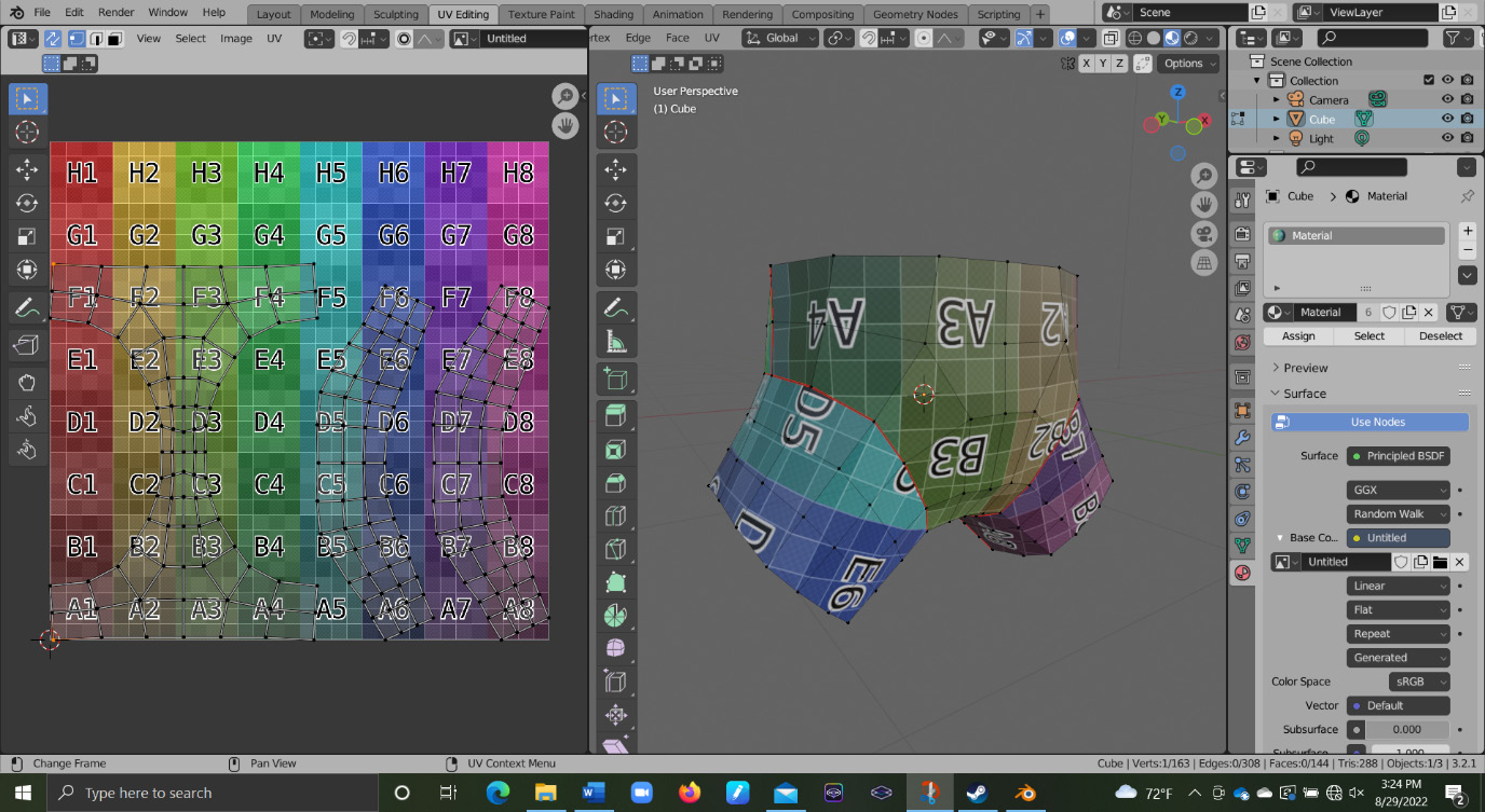
Figure 4.42 – Final unwrap after using new seams
Now, when we look at our mesh in Object Mode with a texture applied, nothing is terribly warped, and all of our seams are as hidden as they can be if we are going to unwrap like this. Another method to unwrap this shape is along the sewn seams that clothing would have.
This requires our topology to have edges that also follow the clothing seams. For a normal pair of pants, there are usually four major seams that hold the pants together. These seams run up the inside, outside, and crotch of the pants. You can see these seams marked in Figure 4.43.

Figure 4.43 – Seam mapping
When we unwrap the mesh, it should look something like Figure 4.44:

Figure 4.44 – Unwrapped model
This mesh also has minimal warping to the texture on the mesh and displays the grid nicely on the mesh. We can take a closer look at the quality of our unwraps by introducing a new tool in the next section.
Improving unwraps
Our new tool is located in the Overlays tab of the UV Editing area. You can see the Overlays tab open in Figure 4.45:
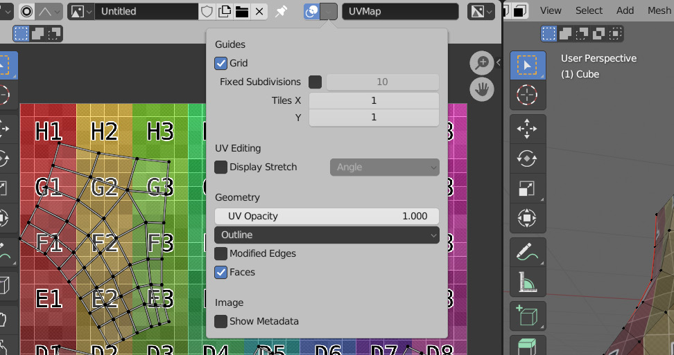
Figure 4.45 – The Overlay tab
In this tab, we can scroll down to the Display Stretch checkbox shown in Figure 4.46:

Figure 4.46 – The Display Stretch option
With this setting, we can check two things: the area of the individual faces, and the amount of deformation each of the faces has. By default, it checks for the angle, but this can be changed in the Overlays tab we just used to enable the setting. With this setting set to Angle, we can see how it affects a cube in Figure 4.47.

Figure 4.47 – Affected cube model with new settings
Notice how all of the faces are blue. This means that there is no warping because all of the faces are being warped from how they are actually shaped on the mesh. Notice how if we move a point on the mesh, or if we move a vertex in the UV editor, the UV map starts to turn green, and then red on the vertices it is affecting. Figure 4.48 shows a vertex in the UV editor being moved.
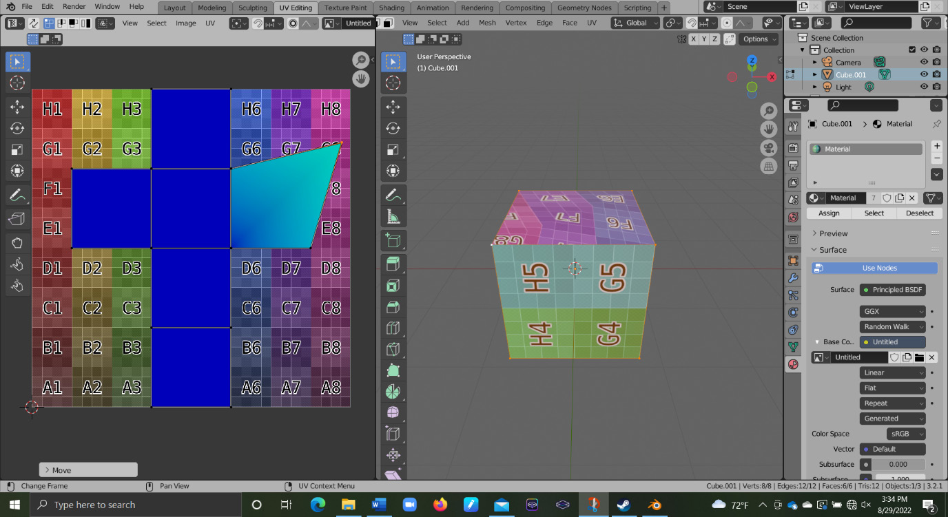
Figure 4.48 – Moving a vertex in the UV editor
This can be corrected by either moving the mesh or the UV map to match the shapes as much as possible. When unwrapping a finished mesh, that usually means tweaking the UV map. This is often a good indication of whether you have enough seams on your UV map, or whether you have them placed well enough. If you unwrap your mesh and there is a dramatic amount of warping, you will likely have to change your unwrap.
The final thing you want to think about when unwrapping your model is something called texel density. Texel density is the size of the face in relation to how much space it takes up on the texture. If we look back at our pants example, with the separate UV islands, we can see this in practice. In Figure 4.49, we can see the two legs next to each other with different texel densities.

Figure 4.49 – Different texel densities
The leg on the left has a shrunken UV. This reduces the texel density of that leg because it is taking up less space on the texture and, by extension, makes the texture look bigger on the mesh. The leg on the right has an enlarged UV. This increases the texel density and makes the texture look smaller because it takes up more space. This is how you can control what parts of the mesh get more detail than others. Have a higher texel density on the parts you want more detail on, to allow them to take up more space on the texture. This is something we need to control on each of our unwraps, and we need our mesh to have as consistently sized quads as possible to help with this.
Thankfully, if we observe all of our previous topology rules up until this point, our only trouble should be in marking our seams properly, but if you find that you are unable to get the result you want regardless of the seams, it likely means that you violated a rule earlier on.
Summary
In this chapter, you learned how to mark seams, UV-unwrap your mesh, and apply a texture to a mesh to check your UV. We also understood where to put our seams when unwrapping and which topology rules affect UV unwrapping the most. By now, you should be able to use UV unwrapping to check your topology and know how to check the quality of your UV map.
UV unwrapping is the last point to check your topology before doing all of the materials and rigging if your model calls for those, so it is important that you catch any major issues here. Otherwise, you may need to redo a tremendous amount of work. With these last considerations you need when preparing for UV unwrapping taken care of, we should be ready to go straight into a more complex model. In the next chapter, we will take a look at a character’s head, and apply all of the topology rules we have learned in this chapter to that model.