The camera as a production tool
Television broadcasting is a high technology industry. Digital manipulation can transform video images and computer graphics can generate scenery, animate characters and create fantasy worlds impossible to build and tape in three-dimensional space.
Despite these visual riches, most television programmes involve people and use cameras as the first stage in acquiring material. The video camera is the most creative production tool available and although a highly sophisticated piece of electronic equipment, its value in programme production depends on the techniques deployed by the camera operator. Its operational characteristics as a production tool are vital but its electronic performance is also crucial in camerawork. A knowledge of how a camera and lens turn light into electricity and the methods of controlling and creatively exploiting that transformation are the foundation on which to build multicamera operational skills in programme making.
Turning light into electricity
Light passing through the lens is split by a prism into red, green and blue components and filtered on to three or more charge-coupled devices (CCDs). The charge induced in the CCDs by the intensity and colour of the scene brightness is extracted by a series of synchronized lines and combined to make up the standard TV signal (see opposite).
Composite
The PAL colour system is the result of adding a chroma signal to an existing 625 line monochrome system to carry the colour information. The three colour signals obtained from splitting the light in the camera prism are the primary colours for the television additive colour system. Various combinations of these three primaries will produce the remaining colours. The amplitude of the individual colour signals from the three camera sensors is proportional to the mix of colours in shot.
By combining proportions of the red, green and blue signals, a luminance signal (Y) (monochrome picture) is produced which corresponds to picture brightness. The three colour signals generated in the camera are encoded (combined) with the luminance signal to form a single composite signal. This is an analogue signal where the amplitude at any moment is proportional to the picture brightness at that point.
Component
Until recently the composite signal was the normal form of signal passed between all production equipment before being transmitted. With the introduction of digital effects, frame stores and component VTRs it was seen to be an advantage to keep the signal in a separated form until transmission, sent as luminance (commonly called the ‘Y’ signal) representing reflected scene light levels, together with two colour components for blue and red (commonly called Cb and Cr). Green information is electronically derived from luminance and the other colour components, at the receiving end of the chain.
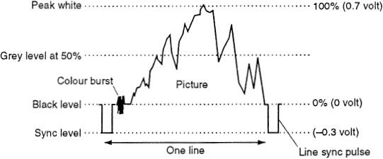
The waveform of the 1V television signal divides into two parts at black level. Above black, the signal varies depending on the tones in the picture from black (0 V) to peak white (0.7 V). Below black, the signal (which is never seen) is used for synchronizing the start of each line and frame. A colour burst provides the receiver with information to allow colour signal processing.
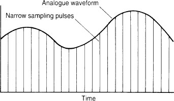
The continuously varying voltage of the TV signal (the analogue signal) is measured (or sampled) at a set number of positions per television line and converted into a stream of numbers (the digital signal) which alters in magnitude in proportion to the original signal.
Storing the signal as binary numbers (ones and zeros) has two advantages. It provides a robust signal that is resistant to noise and distortion and can be restored to its original condition whenever required. Secondly, it enables computer techniques to be applied to the video signal, creating numerous opportunities for picture manipulation and re-ordering the digital samples for standards conversion.
Digital
The analogue signal can suffer degradation during processing through the signal chain, particularly in multi-generation editing where impairment to the signal is cumulative. By coding the video signal into a digital form, a stream of numbers is produced which change sufficiently often to mimic the analogue continuous signal.
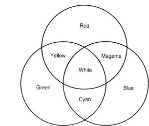
Additive colour system
Colour television transmission relies on an additive colour system of green, red and blue combining in different ratios to produce all the colours in the spectrum. A combination of 30% of red, 59% of green and 11% of blue will produce one unit of white and it is white that requires the greatest attention in camera line-up.
A white card will change its appearance depending on the colour of the light source that is illuminating it. The eye adjusts to the colour difference between the ‘white’ of a card lit by daylight and the ‘white’ of the same card when illuminated by a normal household bulb (tungsten filament) which has more red than mid-day daylight. To the eye, the card under both light conditions simply looks white – an absence of colour.
But the TV camera makes no mental adjustment. It reproduces accurately the predominant colour of the light source illuminating the white card and if the colour of the main source of illumination changes, the camera needs to be adjusted to reproduce the card as white.
Colour temperature range
A convenient way of defining the colour of a light source is to quote its colour temperature in degrees kelvin (K). Typical values of everyday light sources are:
Average summer sunlight |
5500 K |
Morning/afternoon sunlight |
4000–5000 K |
Sunrise/sunset |
2000–3000 K |
Tungsten lamp |
3200 K |
Colour cameras are designed to operate in a tungsten environment. Processing of the output from the red, green and blue sensors is normalized to signal levels produced by a scene lit with tungsten lighting (3200 K). When the camera is exposed to daylight, it requires significant changes to the red and blue channel gains to achieve a ‘white balance’.
In-camera filters
To ‘equalize’ the daylight to tungsten and so reduce this problem, the cameras are fitted with a filter wheel in front of the light-splitting block. This allows the insertion of a minus blue filter (an orange filter) for scenes when the camera is exposed to daylight (5600 K filter position).
Other filters usually found in a filter wheel (some cameras have two wheels) are various grades of neutral density filter which reduce the amount of light by measured amounts without causing a colour cast. Effects filters are also often fitted such as star bursts which, depending on individual filter design, produce either a four-, six- or eight-point ‘star’ flare from a highlight.
Three colour signals are produced by splitting the light into three channels. Colours that are composed of two or more primary colours produce proportional signals in each channel. The luminance signal is obtained by combining proportions of the red, green and blue signals.
A card placed in front of the lens that produces a signal with the proportions of 30% from the red channel, 59% from the green channel and 11% from the blue channel will be transmitted as white.
Independent of the colour temperature of the light illuminating the card, if the signal can be adjusted in the camera to produce a ratio 30%R + 59%G + 11%B (the process called white balancing) then the card will be transmitted as white.
Colour temperature is measured in degrees kelvin (K)
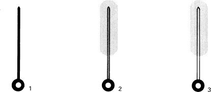
1 Iron rod at room temperature 18 °C.
2 Iron rod heated to 3473 °C (3200 K) produces light of a colour temperature equivalent to light produced by a tungsten filament.
3 Iron rod heated to 5873 °C (5600 K) produces light of a colour temperature equivalent to North European average summer sunlight.
Operational aspects of the camera
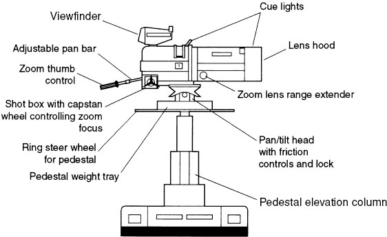
The professional broadcast video camera used in multi-camera production consists of a zoom lens (usually servo-controlled from behind the camera) attached to a camera body containing three or four light sensors (CCDs), electronic circuits to process the signal, an electronic viewfinder mounted on top of the camera and various production facilities such as talkback, filter controls, mixed viewfinder switches, etc.
The three vital facilities that keep the camera operator in touch with programme production are viewfinder, talkback and cue lights. Without a good quality viewfinder he/she is unable to frame up and focus the shot. Without talkback and cue lights, he/she is unaware when the shot will be taken.
Operational controls which have a significant influence on the operation of the camera and transform it from an electronic device into a programme production tool are as follows:
![]() servo controls of the zoom lens which allow a smooth take-off, precise control of speed of zoom and positive focus.
servo controls of the zoom lens which allow a smooth take-off, precise control of speed of zoom and positive focus.
![]() a pan/tilt head to enable the fluid control of camera movement. The pan/tilt head should be adjustable to achieve precise balance in order to cater for a wide range of camera/lens combinations and additional attachments such as prompters. It should also have the facility to accommodate the varying centres of gravity (CoG) of different lens/camera/viewfinder combinations.
a pan/tilt head to enable the fluid control of camera movement. The pan/tilt head should be adjustable to achieve precise balance in order to cater for a wide range of camera/lens combinations and additional attachments such as prompters. It should also have the facility to accommodate the varying centres of gravity (CoG) of different lens/camera/viewfinder combinations.
![]() a camera mounting which allows the camera operator to position the camera and lens quickly, smoothly and with precision for the desired shot and for the camera to remain at that setting until it is repositioned.
a camera mounting which allows the camera operator to position the camera and lens quickly, smoothly and with precision for the desired shot and for the camera to remain at that setting until it is repositioned.
In addition to the operational controls there is obviously a requirement that cameras produce a high quality electronic picture. This will depend on the design characteristics of the camera’s performance such as its sensitivity, resolution, contrast range, etc.
The technical quality of the image produced by the camera has an important influence on how the viewer responds to the production. However, the priorities for a camera operator are often centred on the handling ability of the camera, lens and mounting plus the need to work with a reasonable depth of field in an ad-lib situation coupled with the necessity of seeing the focus zone in the viewfinder. In addition, good communications are vital whether in a crowded studio or a remote location. If the operators cannot hear or talk to the control room, then their contribution is severely impaired.
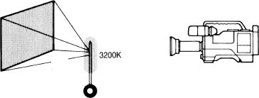
White card illuminated by light source with a colour temperature of 3200 K.
Select filter position on camera – clear glass.
White balance adjusts channel outputs in the proportions of 0.30 red; 0.59 green; 0.11 blue which when combined produce white.
White balance with daylight equivalent
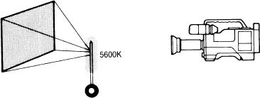
White card illuminated by light source with colour temperature of 5600 K equivalent to daylight.
Select minus blue filter position on camera.
The filter removes a percentage of blue and the white balance returns the output of the 3 channels to the proportions of 0.3 red, 0.59 green and 0.11 blue.
Exposure
A basic requirement in multi-camera productions is that there are no mismatches of exposure or colour rendition when cameras are intercut. This is achieved by remotely controlling the aperture (affecting exposure) and colour adjustment of each camera by vision control where the output of each camera is compared, adjusted and matched. Built-in neutral density (ND) filters and colour correction filters between lens and CCDs can also be switched in when required.
Lightweight vs main line cameras
Development in technology has allowed cameras used in multi-camera productions to become smaller and smaller. Miniaturization has brought gains and losses for camera operators. The gains have included easier rigs and de-rigs, remote control of cameras on cranes and access to areas previously restricted by the size and weight of larger cameras and mountings. The disadvantages have included tiny switches which are difficult to use at speed, especially when gloves are worn on location, the lack of a full range of production facilities such as controllable cursors in the viewfinder, a range of mixed viewfinder sources, easy access to filter controls, shot box facility and a smaller, limited movement range of the viewfinder.
Lightweight lens servo controls are sometimes not as positive or operationally as sensitive as those found on larger lens packages. A compromise solution is to mount a lightweight camera with large viewfinder and box lens (a large diameter lens encased in a protective cover) in a purpose built harness which has the same approximate ‘feel’ and zoom range as a standard, full facility camera.
Facilities found on a multi-camera production camera
The operational use of each of the following camera facilities is described in greater detail in a later section of the manual.
![]() An electronic viewfinder which is usually monochrome although some cameras have the choice of colour or mono. Focusing of a broadcast video camera is through the viewfinder. The definition of the electronic picture therefore must allow the camera operator to be the first person in the production chain to see loss of optical focus.
An electronic viewfinder which is usually monochrome although some cameras have the choice of colour or mono. Focusing of a broadcast video camera is through the viewfinder. The definition of the electronic picture therefore must allow the camera operator to be the first person in the production chain to see loss of optical focus.
![]() Viewfinder controls – brightness, contrast, peaking (to accentuate edge definition as an aid to focusing); may also have controls for viewfinder image size.
Viewfinder controls – brightness, contrast, peaking (to accentuate edge definition as an aid to focusing); may also have controls for viewfinder image size.
![]() Mixed viewfinder controls enable the viewfinder picture to be switched to other video combinations.
Mixed viewfinder controls enable the viewfinder picture to be switched to other video combinations.
![]() Cue lights in the viewfinder, on the front of camera and on the front of the lens are lit when the camera output is selected at the vision mixing panel. Cue lights outside the viewfinder (on the camera body and lens) can be switched out of circuit if required.
Cue lights in the viewfinder, on the front of camera and on the front of the lens are lit when the camera output is selected at the vision mixing panel. Cue lights outside the viewfinder (on the camera body and lens) can be switched out of circuit if required.
![]() Zoom lens – available in a range of zoom ratios.
Zoom lens – available in a range of zoom ratios.
![]() Lens hood – helps control flare and degradation and acts as partial protection against rain.
Lens hood – helps control flare and degradation and acts as partial protection against rain.
![]() Zoom thumb control on adjustable pan bar.
Zoom thumb control on adjustable pan bar.
![]() Zoom focus capstan wheel on pan bar.
Zoom focus capstan wheel on pan bar.
![]() Range extender for zoom lens.
Range extender for zoom lens.
![]() Shot box pre-sets a range of zoom angles of views.
Shot box pre-sets a range of zoom angles of views.
![]() Headset and headset jack points for talkback from and to the control room staff.
Headset and headset jack points for talkback from and to the control room staff.
![]() Talkback volume controls production and engineering talkback and programme sound level to the headset.
Talkback volume controls production and engineering talkback and programme sound level to the headset.
![]() Filter wheel – fitted with a range of colour correction filters, neutral density and effects filters.
Filter wheel – fitted with a range of colour correction filters, neutral density and effects filters.
![]() Crib card holder and sometimes crib card illumination.
Crib card holder and sometimes crib card illumination.
Full facility camera controls
Viewfinder controls
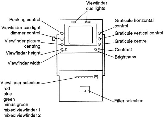
Image size
The image formed by the lens on the face of the pick-up sensors (tube or CCD) is called the image size of the lens. This must match the camera sensor which varies in size although the majority of broadcast cameras are fitted with ⅔ inch CCD. For example, the image formed by a lens designed for a ⅔ inch CCD camera is a circle with a diameter of 11 mm whereas the image size of a lens for a NHK HDTV 1125 CCD camera is 16 mm.
Lenses designed for different sized formats (pick-up sensor dimension) may not be interchangeable. The image size produced by the lens may be much smaller than the pick-up sensor and probably the back focus (flange-back) will not have sufficient adjustment.
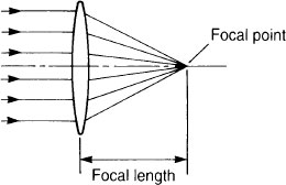
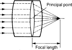
Focal length
When parallel rays of light pass through a convex lens, they converge to one point on the optical axis. This point is called the focal point of the lens. The focal length of the lens is indicated by the distance from the centre of the lens or the principal point of a compound lens (e.g. a zoom lens) to the focal point.
The longer the focal length of a lens, the smaller its angle of view and the shorter the focal length of a lens, the wider its angle of view.
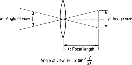
Angle of view
The approximate horizontal angle of view of a fixed focal length lens can be calculated by using its focal length and the size of the pick-up sensors of the camera.
For most broadcast cameras (⅔ inch CCDs) the formula would be:
![]()
Zoom
Although there are prime lenses (fixed focal length) available for some portable ⅔ inch cameras, the majority of cameras are fitted with a zoom lens with an adjustable focal length and therefore an adjustable angle of view over a given range.
This is achieved by moving one part of the lens system (the variator) to change the size of the image and by automatically gearing another part of the lens system (the compensator) to move simultaneously and maintain focus. This alters the image size and therefore the effective focal length of the lens.
Focal length of compound lense
Calculating angle of view
Pre-focusing
When the production requirement is for a zoom-in to a subject, the lens must first be fully zoomed in on the subject and focused, then zoomed out to the required starting shot. The zoom will now stay in focus for the whole range of its travel. If possible, always pre-focus before zooming in.
Zoom ratio
A zoom lens can vary its focal length. The ratio of the longest focal length it can achieve (the telephoto end) with the shortest focal length obtainable (its wide-angle end) is its zoom ratio.
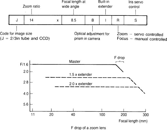
A lens manufacturer will state zoom ratio and the wide-angle focal length in one figure. A ‘14 × 8.5’ zoom lens for a ⅔ inch CCD camera can therefore be decoded as a zoom with a 14:1 ratio starting at 8.5 mm focal length (angle of view = 56°) with the longest focal length of 14 × 8.5 mm = 119 mm (angle of view = 4°). The zoom ratio thus (approximately) equates to ‘14 ×’ i.e. 14 × 4° = 56°.
Lenses with ratios as high as 70:1 can be obtained but the exact choice of ratio and the focal length at the wide end of the zoom will depend very much on what is required from the lens. Large zoom ratio lenses are heavy, often require a great deal of power to operate the servo controls and have a reduced f-number (see below).
Range extender
A zoom lens can be fitted with an internal range-extender lens system which allows the zoom to be used on a different set of focal lengths. A 2×extender on the 14 × 8.5 zoom mentioned above would transform the range from 8.5–119 mm to 17–238 mm but it may also lose 2 stops approaching maximum focal length (238 mm).
f-number
The f-number of a lens is a method of indicating how much light passes through the lens. It is proportional to lens diameter and inversely proportional to focal length. For a given focal length, the larger the aperture of the lens, the smaller its f-number and the brighter the image it produces.
f-numbers are arranged in a scale where each increment is multiplied by √ 2 (1.414). Each time the f-number is increased, the exposure is decreased by half.
![]()
Each division on this scale is called a ‘stop’. Half a division would be a ‘half stop’. The effective aperture of a zoom is not its actual diameter, but the diameter of the image of the diaphragm seen from in front of the lens. This is called the entrance pupil of the lens (see diagram opposite).
When the lens is zoomed (i.e. the focal length is altered) the diameter of the lens which is proportional to focal length alters and also its entrance pupil. The f-number decreases as the focal length of the zoom is altered from its widest angle to its smallest angle. This may cause ‘f-drop’ or ‘ramping’ at the telephoto end when the entrance pupil diameter equals the diameter of the focusing lens group and, due to the lens design, cannot become any larger. Increasing the diameter of the focusing lens group to avoid ramping increases the weight and the cost of the lens.
Typical manufacturer’s zoom code
Ramping
When zooming in, entrance pupil becomes larger until it equals diameter of focusing lens group and cannot increase in size. f-drop or ramping may cause underexposure at low light levels.
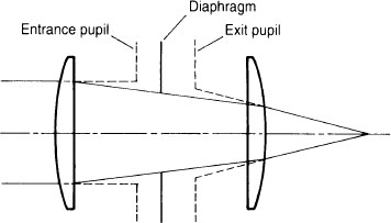
Entrance pupil
In low light conditions (e.g. twilight evening sports events) when the lens aperture may be at its widest at the start of a zoom-in, the picture may be underexposed when the zoom reaches its longest focal length.
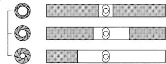
Depth of field
Changing the f-number alters the depth of field – the portion of the field of view which appears sharply in focus. This zone extends in front of and behind the subject on which the lens is focused and will increase as the f-number increases (see diagram opposite).
The greater the distance of the subject from the camera, the greater the depth of field. The depth of field is greater behind the subject than in front and is dependent on the focal length of the lens.
f-number and therefore depth of field can be adjusted by altering the light level or by the use of neutral density filters.
Minimum object distance
The distance from the front of the lens to the nearest subject that can be kept in focus is called the MOD – minimum object distance. A 14 × 8.5 zoom would have a MOD of between 0.8 m and 0.65 m whereas a larger zoom ratio lens, for example, 33:1, may have a MOD of over 2 m.
Macro
Many zooms are fitted with a macro mechanism which allows objects closer than the lens MOD to be held in focus. The macro shifts several lens groups inside the lens to allow close focus but this prevents the lens being used as a constant focus zoom.
Flange-back (back focus)
Flange-back (commonly called back focus) is the distance from the flange surface of the lens mount to the image plane of the pick-up sensor. Each camera type has a specific flange-back distance (for example, 48 mm in air) and any lens fitted to that camera must be designed with the equivalent flange-back. There is usually a flange-back adjustment mechanism of the lens with which the flange-back can be adjusted by about 0.5 mm. It is important when changing lenses on a camera to check the flange-back position is correctly adjusted (see opposite) and to white balance the new lens.
Glass compensation
A television zoom lens is designed with reference to the beam-splitting prism of the camera it is to be used with. The lens and the prism block glass path needs to be predicted to allow glass compensation to be part of the lens design. Some lens manufacturers indicate the compensation in the lens code number (e.g. Cannon J18 × 9B4 lens – the letter B indicates the lens is glass compensated and the following number 4 indicates the type of compensation).
Depth of field is greater behind subject in focus than in front.
Adjusting flange-back (back focus)
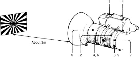
1. Set the IRIS selector to Manual.
2. Place star burst lens chart at approx. 3 m or more and open aperture to maximum. Adjust for correct exposure by using either ND filters or adjusting light on the chart.
3. Zoom in on star burst chart.
4. Adjust for sharp focus on chart with front focus ring.
5. Zoom out to widest angle.
6. Loosen the flange-back (fF) adjustment ring lock screw.
7. Adjust fF for optimum definition on chart.
Do not touch zoom focus ring.
(NB FLANGE-BACK position should be close to standard marked position on lens)
8. Repeat steps 4 through to 7 until focus is correct at telephoto and wide angle positions.
9. Tighten the fF adjustment ring lock screw.
Switch in RANGE EXTENDER. Zoom in and focus. Zoom out and check that zoom holds focus over complete range.
Horses for courses
There is a wide range of camera mountings available to cover the diverse requirements of multi-camera programme making in the studio and on location. No one camera mounting will necessarily embrace all styles of camerawork and all weights of equipment.
The first selection criterion is to know if the mounting is to be transported to its operating position (i.e. at a location rather than operated daily in a studio). Equipment that has to be carried up stairs or rigged in difficult locations needs to be lighter and more easily rigged and de-rigged compared to equipment used permanently in a studio.
The second consideration is if the mounting is to be used to reposition the camera ‘on shot’ or if it is simply needed to reposition ‘off shot’. A tripod on wheels (if the ground surface is suitable) can be repositioned to a new camera position but is unsuitable for development shots. A pedestal mounting with steerable wheels and smooth adjustment of height will allow a development on shot if operated on a level floor.
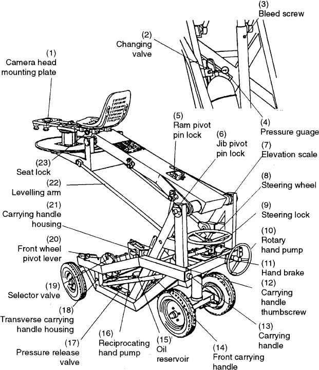
The third consideration is the total weight of camera, lens and, possibly, camera operator, which the mounting will need to support. The simplest way of moving a lightweight camera is to carry it on the shoulder (on or off shot) although this will not give such a smooth movement as using a harness around the torso to steady the camera. There is a range of lightweight tripods, portable pedestals and jib arms that can be used with a lightweight camera. There is also the facility to rig a lightweight camera on the end of a boom arm and move it on a servo driven pan/tilt head and to control the lens using remote controls. At the other end of the scale there are cranes capable of elevating a full facility camera and camera operator to a lens height of over 6 m (20 ft).
Pan/tilt heads
A good pan and tilt head will have adjustment for the centre of gravity (CoG) of the combination of camera/recorder, lens and viewfinder in use. If the CoG is not adjusted the camera will either be difficult to move from the horizontal or it will tilt forwards or backwards. Adjustment of the CoG balance should not be confused with mid-point balance, which involves positioning the camera and lens to find the point of balance on the head.
The setting of the friction or drag control of the head depends on the shot and personal preference. Using a very narrow lens for an extreme close shot (e.g. a bird nesting) may require much more friction than that needed to pan the camera smoothly when following rapid impromptu movement (e.g. skating). Some camera operators prefer a heavy drag or ‘feel’ on the head so that there is weight to push against while others remove all friction, allowing the head to be panned at the slightest touch.
Full facility camera pan/tilt head
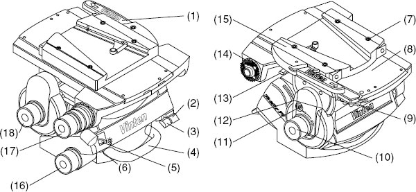
(1) wedge adaptor operating lever, (2) pan friction brake lock, (3) tilt friction brake lock, (4) carrying handle, (5) level bubble, (6) level bubble light switch, (7) wedge adaptor fixing bolts, (8) sliding plate, (9) sliding plate adjustment knob, (10) centre of gravity balance control, (11) tilt axis centre lock, (12) centre lock release, (13) sliding plate clamp, (14) pan bar mounting point, (15) wedge plate adaptor, (16) pan drag adjustment knob, (17) pan bar clamp, (18) tilt drag (friction) adjustment knob.
Warning: Do not rely on the tilt brake (3) when changing cameras. Always engage the centre lock (11).
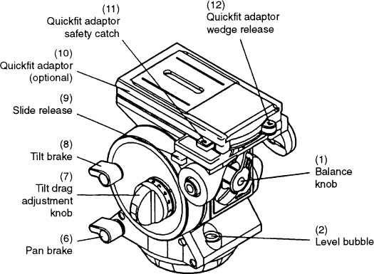
Lightweight camera pan/tilt head
A television studio equipped to mount live and recorded multi-camera productions usually contains three main areas: the studio floor area, the control rooms and a series of production rooms.
The studio floor area
The studio floor surface needs to be absolutely level and free from bumps, cracks or unevenness. One of the basic needs of multi-camera work is to move the camera on shot smoothly and quietly without the use of tracks or boards. If the floor surface cannot accommodate camera movement on shot then it is unsuitable for the production of continuous multi-camera programme making.
Most broadcast studios are equipped with at least three cameras with provision for additional cameras as required. The standard mounting for the camera is usually a pedestal but alternative mountings such as a tripod, dolly, jib arm or crane may be used depending on the requirements of the production. When not in use, the cameras may be stored in a technical storage area which is off the studio floor. Often they are covered and left in an area of the studio floor so as not to obstruct the scenery and lamp de-rigging and the subsequent rig for the following show. Storage area is also required for camera cables, monitors, sound and lighting equipment.
Access for scenery is through large double doors. There must be sufficient grid height overhead to accommodate a cyclorama, a 5 m+ cloth that is stretched taut in an arc around one, two or three sides of the studio to provide a lit backing. Suspended from the grid are lighting hoists that can be lowered for rigging lamps and individually routed to a numbered input into the lighting console. Access to the grid area is often required for rigging lamps, monitors, speakers and suspended scenery. Electrically-driven hoists are used to suspend scenery and for flying in scenery pieces. Other hoists may be available for audience monitors and speakers or simply to liberate more floor space.
The studio walls are usually acoustically treated to improve the sound handling qualities. Installed at strategic positions along the studio walls are the technical facilities commonly called wall boxes. Monitors, microphones, foldback loudspeakers, technical mains and talkback can be plugged into these boxes to provide flexibility in technical rigging depending on the production layout. Positioned on the studio wall may be outlets for water, gas, etc. for production purposes.
Studios require air-conditioning to extract the heat generated by the lamps and a ‘house’ lighting system (plus emergency lights), when studio lamps are not switched on for rigging and de-rigging. Fire alarms and fire lanes are required to provide an unimpeded route for audiences and production staff to the fire exits.
Close to the studio may be make-up rooms, wardrobe and dressing rooms, property/scenery store all usually equipped with a double door sound lock to prevent noise leaking from these working areas into the studio when recording or ‘on transmission’.

Cable points
Cable points may be part of the wall box or be separate points around the studio alphabetically numbered. This allows Camera 1, for example, to be cabled to camera point D, Camera 2 cabled to camera point G and so forth. The cable point for each camera may be decided at the planning meeting or agreed during the rig. All the cable points terminate in a technical area where, depending on which camera is routed to which point, the appropriate camera channel can be routed to the correct camera.
Warning lights above each entrance to the studio are installed to inform people about to enter the studio of its status – empty (unlit), in REHEARSAL or in TRANSMISSION. A red light indicates that a recording or transmission is in progress and the studio should not be entered.
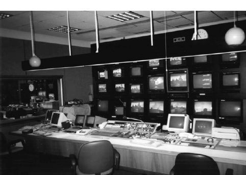
The control room
Away from the studio floor area are the production control rooms. If they are sited above the floor level, there is often quick access via stairs straight on to the studio floor. The main studio production control room contains a vision mixing panel, a talkback system and communications to other technical areas, possibly a caption generator for in-vision text and possibly the control system of the prompter device. All the equipment is housed in a long customized desk facing a bank of preview picture monitors displaying each video source used in the production.
Some of the preview monitors may be switchable depending on the number of video sources used in the production. These will include each camera’s output, VTR, telecine and frame store outputs, any input from an outside broadcast that may be used or other studio inserts, caption generator and electronic graphics output, electronic VTR clock, a special effects output and a ‘studio out’ monitor displaying the visual source that is selected at the vision mixing panel. Other monitors may provide feeds of programmes currently being transmitted. Prominent on the monitor bank wall will be a large clock plus an indication of the studio status (e.g. blue light: ‘rehearsal’, red light: ‘transmission’)
Sound, lighting and vision control
Adjacent to the production control room (commonly called the ‘gallery’) is the sound control room where the audio inputs to a programme are mixed. Opposite a bank of preview picture monitors and monitoring loudspeakers is a sound desk used to control the level and quality of all audio outputs. There will also be audio record and replay equipment.
Lighting and vision control usually share the same room and are equipped with preview monitors, a lighting console to control lamp intensity and for grouping lamps for coordinated lighting changes. A diagram of the lamps in use (mimic board) helps the console operator during rehearsal and transmission. Alongside the lighting area is the vision control panel which houses the controls for altering the exposure, black level, colour balance, gain and the gamma of each camera. From this position, the vision control engineer matches each camera’s output so that, for example, the skin tones of a face that is in shot on several cameras is the same.
Each studio camera has its associated bay of equipment housed in the vision control room or in a technical area adjacent to the control rooms. Vision control also needs communications to other technical areas.
Other production facilities used in multi-camera programming are a graphics area which feeds electronic graphics, animations and electronic text to the studio, a technical area where telecine, video, slide store machines are centrally available and allocated according to production requirements. Half inch VTRs are often located in the production control room.
Studio control room
Two other rooms connected with programme making are the production office which is the base for the planning and preparation of a programme, and a green room or hospitality room which is used for the reception of programme guests before and after the programme.
Studio and OB equipment
An outside broadcast (OB) is any multi-camera video format programme or programme insert that is transmitted or recorded outside the studio complex. Most of the equipment permanently installed in a studio complex (see Control rooms, page 36) is required for an outside broadcast. Production, sound, engineering and recording facilities are usually housed in customized vehicles (often referred to as ‘scanners’) or as a travelling kit of lightweight, portable vision mixing panels, video tape recorders and associated engineering equipment, sound mixers, etc. housed in cases and reassembled in a suitable area at the location (e.g. for drama production).
In general terms, studio productions have more control of setting, staging, programme content than an outside broadcast. There is a logistic difficulty in duplicating all these facilities outside the studio but location recording offers the advantage of complex and actual settings plus the ability to cover a huge range of events that are not specifically staged for television. Outside broadcast camerawork tends to be involved in a higher proportion of live or ‘recorded-as-live’ productions plus a greater number of ‘as-directed’ programmes (i.e. non-camera scripted).
Covering large-scale events means that cameras are scattered a long way from the scanner and camera operators in general need to be more self-sufficient without the immediate technical back-up often available in broadcast studios.
Outside broadcast vehicles
The main OB vehicle houses the control room which serves the same function as a studio control but the equipment and operating areas are designed and compressed to fit a much smaller space.
Technical support vehicles are used for transporting cable, sound and camera equipment, monitors, lighting gear and other production facilities that may be required. In addition there may be a separate VTR vehicle equipped with recording and slow motion machines, etc.
For a live transmission, there will be a radio links vehicle or portable equipment which may be a terrestrial or a satellite link or alternatively a land line that carries the programme back to a base station or transmitter. The number of vehicles on site will increase with the complexity of the programme and the rig. There may be props, scenery, furniture to be delivered to the site. Dressing rooms, make-up and catering may be required.
In many ways an OB convoy is similar to a circus. It travels to a location, rigs and prepares for the show, records or transmits a ‘performance’, derigs and moves on. At all times it must plan to be self-sufficient in facilities and staff and to carry to the location all that is required for the programme.