
IN THIS CHAPTER
Chapter 4, “Configuration Manager Solution Design,” discussed how using the framework of a solutions-based architecture could help to unleash the value of System Center Configuration Manager (ConfigMgr). Since today’s Information Technology (IT) solutions typically are delivered in a networked environment, effectively planning and implementing a ConfigMgr implementation is contingent on understanding your network, including the resources it offers and the limitations it imposes.
Central to the planning process is the reality that communication between systems is dependent on the network that connects them. Understanding how ConfigMgr lives within the network will help you design, deliver, and manage successful solutions to meet your business objectives. A recurrent issue with management solutions is providing the required core management services—without consuming excessive network resources or adversely affecting other network activity. When you start planning your Configuration Manager deployment, you should review all available network documentation and engage the team that supports the network in your organization. A consideration of how ConfigMgr will affect your network is critical to the success of your deployment.
This chapter discusses the ways in which Configuration Manager uses the network, with approaches for optimally delivering solutions in various network environments. The discussion includes the following areas:
• Discussing the network requirements for each ConfigMgr communication process.
• Understanding how Configuration Manager deals with fast and slow networks.
The Background Intelligent Transfer Service (BITS) is a key enabling technology in delivering Configuration Manager services. The chapter includes a detailed discussion of BITS to help in implementing and troubleshooting these services.
• Evaluating which network conditions to consider when designing your ConfigMgr hierarchy and server placement.
• Examining the special challenges around mobile, disconnected, and sometimes connected users.
• Considering how you can use Configuration Manager to discover network resources.
• Using Internet Protocol (IP) subnets and Active Directory (AD) sites to optimize delivery of services to your client systems.
• Discussing network communication problems that may occur and how to troubleshoot them.
After you complete this chapter, you should have a fundamental understanding of how Configuration Manager works in a networked environment. You will be able to use your knowledge of Configuration Manager networking to optimize your deployment and effectively troubleshoot network-related issues.
Configuration Manager clients and server systems use a variety of protocols to communicate with each other across the network. The following sections discuss the network communications between server roles within a site, the communications of ConfigMgr clients with servers in the site, and communications between sites.
As previously described in Chapter 2, “Configuration Manager 2007 Overview,” a ConfigMgr site contains of a set of servers carrying out various system roles. In the simplest configuration, the ConfigMgr site server holds all deployed site system roles. Designs that are more complex may involve moving certain roles to other servers within the site. Assigning roles to multiple servers brings network considerations into play for intrasite communications. This section discusses the protocols used for network communications and the flow of information between site systems. For information on how network considerations affect your decision of how to distribute server roles, see the “Server Placement” section of this chapter.
Configuration Manager site systems use various protocols to communicate with each other. The most important protocols include the following:
• Configuration Manager site systems use standard SQL Server communication protocols to talk to MicroSoft SQL Server.
• The site server and other systems use the Remote Procedure Call (RPC) protocol to invoke remote functionality on other systems.
• Most file-transfer operations use the Server Message Block (SMB) protocol.
• BITS and various other services use Hypertext Transfer Protocol (HTTP) and/or Secure Hypertext Transfer Protocol (HTTPS).
The following sections discuss the specifics of these protocols.
With Configuration Manager 2007, SQL Server connectivity uses standard SQL Server TCP/IP communications. Microsoft reserved Transmission Control Protocol (TCP) port 1433 as the default port with the default SQL Server instance; for named instances, the port is dynamic and is not 1433—the SQL Browser listens on User Datagram Protocol (UDP) port 1434 and directs the connection to a dynamically chosen TCP port. You can use the SQL client network configuration tools and server setup to specify a port other than 1433 for the default instance. For additional information on changing the port used by SQL Server, see http://support.microsoft.com/kb/823938, which describes static and dynamic port allocation as well as configuring SQL Server to use a static or dynamic port. Although ConfigMgr supports Named Pipes connections to SQL Server, you should use the Named Pipes protocol for troubleshooting only.
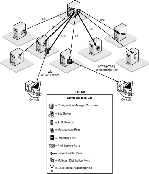
The primary site server, SMS provider, and management point all make intensive use of SQL Server. The reporting point, PXE (Preboot Execution Environment) service point, and server locator point (SLP) also access the database directly. In Configuration Manager 2007 Release 2 (R2), the reporting services point, multicast-enabled distribution point, and client status reporting host also connect to the site database.
Note
About Named Pipes
Named Pipes uses NT LAN Manager (NTLM) authentication only and does not support Kerberos authentication. Kerberos provides mutual authentication of the client and server, whereas NTLM authenticates the client only. TCP/IP also provides better performance under challenging network conditions such as across a wide area network (WAN) link.
The Configuration Manager console accesses the site database using the SMS provider, which is an intermediate Windows Management Instrumentation (WMI) layer used for database communication. Figure 5.1 shows the systems that communicate with SQL Server. The figure does not show other communications involving these site systems, such as communications with the site server or with clients.
RPC is an industry-standard protocol used to invoke code across process boundaries, generally between processes on different machines. The calling process initiates an RPC call on TCP or UDP port 135 and receives a response on a dynamically allocated TCP port in the range of 1024 to 5000 (unless you have configured a custom range on your systems, which can be done using the RPC Configuration Tool [RPCCfg.exe] from the Windows Server 2003 Resource Kit). The site server initiates RPC connections for configuring site systems.
Tip
Locating the Windows 2003 Resource Kit Tools
The Windows Server 2003 Resource Kit Tools are available at http://go.microsoft.com/fwlink/?linkid=4544.
SMB is the core protocol for Windows file, printer, and port sharing and for interprocess communications mechanisms such as Named Pipes and Mail Slots. Configuration Manager components rely heavily on file exchanges to communicate with each other, as described in Chapter 3, “Looking Inside Configuration Manager.” Most site systems also pass status message and state message files back to the site server using SMB. SMB traffic involves a series of requests and responses, which can involve multiple roundtrips between the communicating systems. This means that network latency can substantially affect certain SMB communications.
The largest file transfers between site systems involve distributing software packages (including Operating System Deployment [OSD] image files) to distribution points. Transfers from the site server to a standard distribution point use SMB. The Distribution Manager component of Configuration Manager handles distributing packages to the standard distribution points within the site. Branch distribution points use BITS to download packages from standard BITS-enabled distribution points. Packages are sent between sites using the sender mechanism, described in the “Site-to-Site Communications” section of this chapter.
Software distribution settings are located under System Center Configuration Manager -> Site Database -> Site Management -> <Site Code> <Site Name> -> Site Settings -> Component Configuration in the Configuration Manager console. As shown in Figure 5.2, several parameters are available that you can tune to regulate how packages are sent to distribution points. These parameters control concurrent distribution and retry behavior. The first section (Concurrent distribution settings) allows packages to be sent in parallel to more than one distribution point, whereas the second area (Retry settings) controls how often to retry unsuccessful sending attempts as well as the delay in minutes before retrying. The settings in this figure are the default settings.
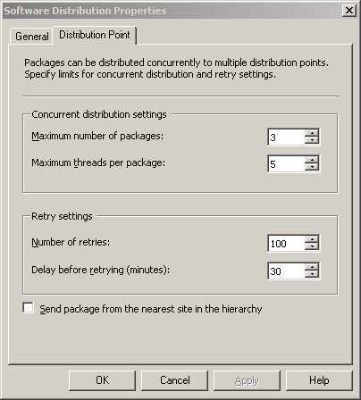
• Maximum number of packages— Specifies the maximum number of packages (from one to seven) that can be copied to distribution points in parallel.
• Maximum threads per package— Specifies the maximum number of threads (from 1 to 50) allocated to each package during distribution. The maximum total number of threads allocated to package distribution is (Maximum number of packages) × (Maximum threads per package).
• Number of retries— Specifies the number of times (from 1 to 1,000) that the Distribution Manager will retry a failed package distribution attempt.
• Delay before retrying (minutes)— Specifies the delay (from 1 minute to 1,440 minutes [24 hours]) before retrying a failed distribution attempt.
The distribution settings dialog box also provides a check box to enable the option Send package from the nearest site in the hierarchy. This option causes child sites to retrieve newly targeted packages from the nearest site at which the required packages are available, rather than from the source site for the package.
Although increasing the maximum packages and maximum threads per package will require more server and network resources, it results in faster package deployment. In many instances, you can increase the maximum number of threads from the default value of 5. Adjustments to these values should be based on the following criteria:
• The available capacity of the network connecting your site server to the distribution points
• Monitoring the bandwidth used by package distribution
The retry and delay settings determine the resiliency of your package distribution if you encounter intermittent connectivity problems. The reliability of your network and the Mean Time To Restore (MTTR) specified in your Service Level Agreements (SLAs) governing network outages determine the optimum settings for your environment.
Caution
Use Care when Adjusting Distribution Point Settings
Changing the distribution point settings shown in Figure 5.2 will have an impact on overall site function. If you are already seeing backlogs in any of the inboxes or sluggish site server processing, adjusting these settings may make overall performance worse.
HTTP and HTTPS (secure HTTP) are used for communication between the site server and the software update point (SUP). Branch distribution points also use these protocols for BITS-enabled transfers of packages from standard distribution points.
At the highest-level site in your hierarchy that has a software update point configured, the SUP will need to connect to the Internet over HTTP to synchronize with Microsoft updates. If the server is not able to connect to the Internet directly, you can specify a proxy server on the ConfigMgr software update point properties page, as displayed in Figure 5.3. To access this page, expand the ConfigMgr Console tree to System Center Configuration Manager -> Site Database -> Site Management -> <Site Code> <Site Name> -> Site Settings -> Site Systems -> <Site System> and then right-click ConfigMgr software update point and choose Properties.
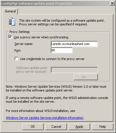
Software update points at downstream sites can synchronize with a Windows Software Updates Server (WSUS) at a higher level of the hierarchy.
When you initially deploy a package to a distribution point, Configuration Manager provides two mechanisms specifically designed to minimize the amount of network traffic generated when replicating changes to the package. These mechanisms are delta replication and binary differential replication:
• Systems Management Server (SMS) 2003 introduced file-based delta replication. When a package is updated, a delta compressed package file—containing only the files that have changed since the previous version—is created in addition to the full compressed package file. The source site server will maintain deltas for up to five versions of a package. Only changed files are sent if the package is sent to a distribution point or site that already has one of the previous five versions of the package.
• A new option in Configuration Manager 2007 is binary differential replication of packages. Binary differential replication works similarly to delta replication, with two exceptions:
• A binary comparison of the files is made.
• Only the portions of the files that have changed are sent, not entire files.
Binary differential replication is highly advantageous for packages consisting of very large files, such as Windows Installer packages or operating system (OS) images.
For packages with many small files, binary differential replication may not be worth the overhead it incurs. You can enable the option to use binary differential replication on a per-package basis. Chapter 13, “Creating Packages,” and Chapter 14, “Distributing Packages,” discuss options for configuring packages and sending them to distribution points.
In addition to communications between Configuration Manager systems, the following basic network services are required:
• Active Directory
• Domain services
• Global Catalog (GC) services
• DNS (Domain Naming Service)
• NetBIOS name resolution (in some configurations)
If you have any of the Active Directory discovery methods configured, a high volume of network traffic will occur between the site server and domain controller (DC) while AD discovery is running. Chapter 12, “Client Management,” discusses Active Directory discovery methods.
Configuration Manager is designed to use Internet standard protocols for most client communications. In addition, most of the client communication ports are configurable. Configuration Manager supports both mixed and native mode sites. In mixed mode sites, most client communications are over HTTP, whereas native mode sites use HTTPS. For more information about mixed versus native mode, see Chapter 6, “Architecture Design Planning.”
Data sent across the network using the TCP or UDP protocol is transmitted in discrete units of data called packets. Each packet includes the following:
• A body that contains the actual data
• A header with addressing and other control information
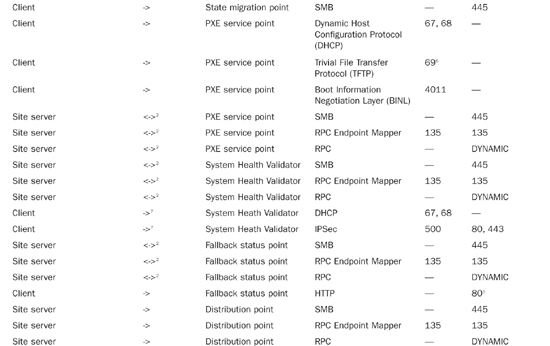
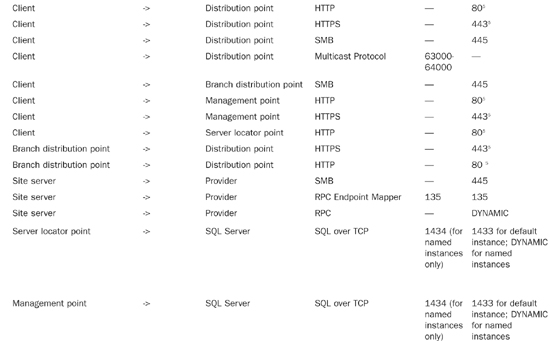
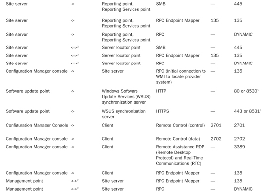
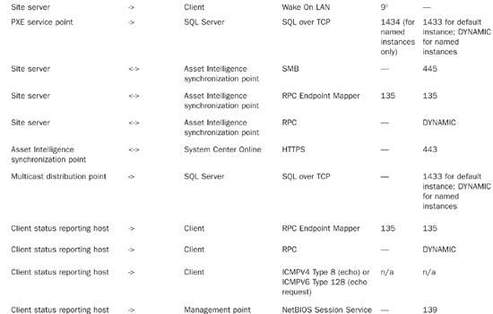
The header includes the IP addresses of the source and destination machines as well as the port numbers of the source and destination services or applications. A port number is a number from 1 to 65535 used to identify the application. An application or service “listens” on a specific port if it has registered with the operating system to receive packets addressed to that port. Like many services, Configuration Manager services have standard ports on which they listen by default.
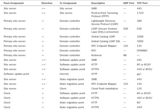
Table 5.1 lists the communications protocols and ports used by various applications and services. You can also find information regarding the communication protocols and ports used by ConfigMgr at http://technet.microsoft.com/en-us/library/bb632618.aspx.

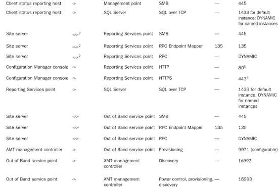
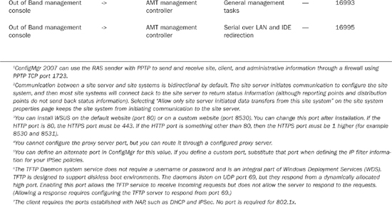
In addition to standard ConfigMgr 2007 traffic, Network Access Protection (NAP) generates the traffic described in Table 5.2. If you use firewalls that block this traffic, you must reconfigure them for NAP to work with ConfigMgr 2007. You will also need to identify ports used by the client to communicate with the System Health Validator point (SHV). The NAP enforcement client you are using determines the ports for system health validation.

Information online regarding ports for NAP in Configuration Manager 2007 is located at http://technet.microsoft.com/en-us/library/bb694170.aspx.
You may choose to use custom rather than standard ports for client-to-server communications for the following reasons:
• Custom ports may be necessary for Configuration Manager to work with your network firewall policies.
• You may also need to use a custom website for ConfigMgr instead of the default site on your Internet Information Services (IIS) servers. Although this is not a best practice, it may be necessary if ConfigMgr is sharing IIS servers with other applications that depend on the default site.
You may specify custom ports for client communications during either Configuration Manager setup or later using the ConfigMgr console:
• During setup, you can specify a custom HTTP port for mixed mode sites or a custom HTTPS port for native mode sites in the Port Settings dialog box, displayed in Figure 5.4.
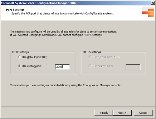
The port specified in Figure 5.4 is used for client-to-server communications by all site systems.
• After setup, you can change your selection and add alternate ports on the Ports tab of the Site Properties sheet in the ConfigMgr console. Perform the following steps:
- Navigate to System Center Configuration Manager -> Site Database -> Site Management -> <Site Code> <Site Name>.
- Right-click the site name, choose Properties, and then select the Ports tab. As shown in Figure 5.5, you can specify both default ports and alternate ports for client communications.
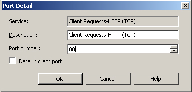
- To enable a port, modify an enabled port or change the default port and then double-click the entry to bring up the Port Detail dialog box shown in Figure 5.6.

Tip
Specifying Different Ports
If you utilize custom ports or custom websites, you should use them consistently throughout your hierarchy. Using different ports or websites at different sites can cause problems as clients roam from one site to another.
Regardless of whether you change the default HTTP and HTTPS ports, it is always a good idea to specify alternate ports to increase the availability of these services.
The initial communication between the client and the ConfigMgr hierarchy occurs during client installation. The sequence of network calls depends on the client installation method used. Client installation methods are discussed in detail in Chapter 12. For purposes of this discussion, there are two general types of client installation methods:
• Server initiated (client push)
• Client initiated (all other methods)
Client push installation includes a preinstallation phase in which the site server connects to the client to initiate installation:
• In the client push installation method, the server makes an initial connection to the admin$ share on the prospective client computer using Windows file sharing protocols.
• The server also establishes a WMI connection to the client using the Distributed Component Object Model (DCOM) through TCP port 135.
DCOM is a Microsoft standard for communication between software components, either on a local computer or across a network. This approach differs from SMS 2003, which used a remote Registry connection rather than WMI.
• The site server uses these connections to copy the required setup files to the client and then installs and starts the ccmsetup service. Additional requirements for client push installation are covered in Chapter 12.
Once the preinstallation phase is complete, the installation proceeds in a manner similar to other installation methods.
Regardless of the client installation method used, the first network-related task for the new client is to locate and contact a management point (MP) for its assigned site. From this point onward, the MP will be the primary point of contact between the client and its site. Unless the client installation source files are staged locally, the setup process uses BITS to pull the files from the CCM_CLIENT website on the MP. Once the client is installed, it continues to communicate with the management point using HTTP or HTTPS, and generally uses BITS to download policy and component updates and to send client information, including inventory, metering data, state messages, and status messages, to the site.
There are three general ways for the client to determine the site it is assigned to as well as to locate the management point for that site:
• Depending on the installation method used, the site code and management point may have been supplied as command-line arguments. The management point may be specified using an IP address, a Fully Qualified Domain Name (FQDN), or a simple name.
• If the information is not provided via the command line, clients in the same Active Directory forest with the site server can generally retrieve this information by querying AD (assuming the schema is extended and the appropriate information is published in AD).
• If the required information is not available in AD, the client must contact a server locator point for site and management point information:
• The SLP may be specified in the command line.
• If the SLP is not provided through the command line, it must be resolved through NetBIOS name resolution.
• If you are using WINS server for NetBIOS name resolution, you must manually add the SLP entry to WINS following the procedure found at http://technet.microsoft.com/en-us/library/bb632567.aspx:
Open a command prompt (Start -> Run, and then type cmd), type netsh, and then press Enter.
Type wins and then press Enter.
Type server and then press Enter.
Type the appropriate command to add the name. Here’s an example:
add name Name=SMS_SLP endchar=1A rectype=0 ip=<server locator point IP
address>
• If a WINS server is not available, you can supply the SLP information using an LMHosts file. The SLP information in LMHosts is as follows:
<SLP IP address > "SMS_SLP �x1a" #PRE.
About HTTP Communications for Native Mode Clients
Server locator points support only HTTP communications; they do not support HTTPS. By default, intranet clients assigned to native mode sites require HTTPS for all web-based communications. If a native mode intranet client needs to contact an SLP, enable the option Allow HTTP communication for roaming and site assignment. This option can be enabled by supplying the /native:FALLBACK switch or the /native:CRLANDFALLBACK switch in the ccmsetup command line.
Enabling HTTP also allows the client to download content from mixed mode sites when roaming within the boundaries of the site. You can apply this option on a sitewide basis, allowing clients already assigned to the native mode site to use downloads from mixed mode sites. The Allow HTTP communication for roaming and site assignment option is located on the Site Mode tab of the Site Properties sheet, displayed in Figure 5.7. To access the property sheet, open the Configuration Manager console and navigate to System Center Configuration Manager -> Site Database -> Site Management -> <Site Code> <Site Name>, then right-click the site name and choose Properties and select the Site Mode tab.
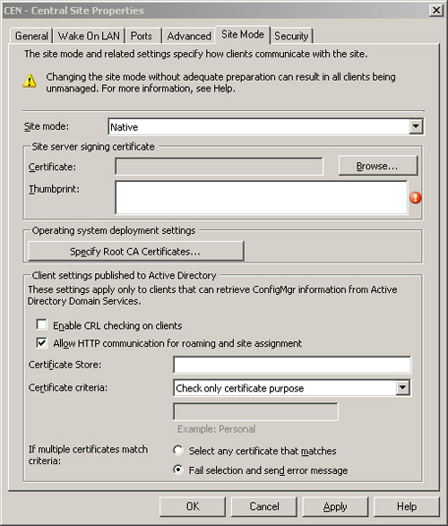
If your installation requires server locator points for site assignment, enable HTTP for native mode clients. HTTP traffic is not encrypted and therefore less secure than HTTPS. If you are considering enabling HTTP for client roaming functionality, you will need to evaluate the tradeoff between security and network functionality.
For more information about security, see Chapter 20, “Security and Delegation in Configuration Manager 2007.” For additional information about client roaming, see Chapter 12.
The Configuration Manager client uses the HTTP or HTTPS protocol exclusively to communicate with the management point and the software update point. These two roles are among the systems having the highest volume and frequency of communication with ConfigMgr clients. Clients communicate with the management point more frequently than with any of the other Configuration Manager site systems.
• Client systems poll the management point regularly for policy updates. The default polling interval is every hour.
• Clients send state, status, inventory, metering, and discovery data to the management point. State information is sent every 5 minutes by default. Inventory, metering, and heartbeat discovery data is sent every 7 days by default.
• You can configure the schedules for clients to pull policy and send state, inventory, metering, and heartbeat discovery data as described in Chapter 12. Choosing a simple schedule for inventory causes the network load to spread over time, because not all clients will send inventory at the same time. A custom schedule provides more control over the timing of inventory collection, but may have considerable impact when inventory runs.
• Initial inventory on new clients is considerably larger than regular inventory updates, which only send a delta (only the files that have changed since the previous version) over the network.
The frequency and size of client downloads of software updates from the SUP depends on how you configure software updates and the client configuration. Many individual software updates are relatively small (a few megabytes or smaller). Some can be quite large, however, including service packs, which can be hundreds of megabytes or even larger.
Tip
Additional information about software updates can be found in Chapter 15, “Patch Management.”
Microsoft generally releases critical security updates for its products monthly on the second Tuesday of the month, known as “Patch Tuesday.” Typically, once you evaluate and approve the Patch Tuesday updates for your environment, you will make them available as a group for distribution to your clients.
Some new features of Configuration Manager 2007 decrease the network impact of software updates. The Software Updates agent uses selective download technology to download only the individual files that the client requires from a software updates package. In addition, supersedence information is provided to help administrators avoid deploying updates superseded by a newer update. Even with these enhancements, software updates can require significant network bandwidth. You will want to consider this requirement when planning your software updates strategy.
Clients use HTTP/HTTPS or the SMB protocol to pull data from distribution points and state migration points:
• Clients downloading a package to their local cache from a BITS-enabled distribution point use BITS over HTTP or HTTPS.
• Clients running the package directly from the distribution point use SMB.
• Clients retrieving packages from branch distribution points use only the SMB protocol.
Depending on the size of the software package, downloads from distribution points can be quite large. Clients do not use either binary differential replication or delta replication; therefore, changes to a package the client has cached will trigger a full download to the client.
Clients use state migration points less frequently, generally during operating system upgrades or hardware replacement. The amount of traffic sent to and from the state migration point depends on the amount of user data to be preserved. For more information about user state migration, see Chapter 19, “Operating System Deployment.”
The remaining site systems handle relatively little client traffic, but use a variety of protocols:
• The PXE service point responds to PXE boot requests and initiates boot image downloads. The PXE boot process is an extension of the DHCP protocol. DHCP is widely used for assigning IP addresses and TCP/IP configurations.
• If you enable Configuration Manager for NAP, clients will pass a statement of health (SoH) to the System Health Validator when making a new DHCP request or a new IPSec (Internet Protocol Security) connection to the network. Once connected, the client will periodically submit a new SoH to the System Health Validator. The default interval for system health to be reevaluated is 24 hours. Chapter 15 discusses NAP in detail.
• The fallback status point, like the server locator point, responds to client requests using HTTP communications only.
• The site server connects to the client when Wake On LAN functionality is required for patch deployment or other activities. The default port for Wake On LAN is UDP port 9; however, you can configure this using the dialog box shown previously in Figure 5.6.
• If administrators use the Configuration Manager Remote Tools, the machine on which the console is running contacts the client directly. Remote tools use the SMS/Configuration Manager Remote Control protocol (UDP and TCP ports 2701 and 2702) to connect to Windows 2000 computers, and RDP (which uses TCP port 3389) to connect to computers running Windows XP or later.
Sites in a ConfigMgr hierarchy must share configuration information, client data such as inventory and discovery data, status information, and so on. Chapter 3 describes the information flow up and down the hierarchy. All data exchanges between sites are transmitted by means of senders. Senders use the SMB protocol to transfer files between sites.
Configuration Manager sites are configured to use networks for site-to-site communications by creating a sender corresponding to the underlying network. By default, each Configuration Manager site has one sender installed—a standard sender. In most cases, the standard sender is the only one you will use. A standard sender uses your primary network for communications.
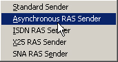
To add, delete, or change the properties of senders from the Configuration Manager console, navigate to System Center Configuration Manager -> Site Database -> Site Management -> <Site Code> <Site Name> -> Site Settings -> Senders. If you have sites connected by any of the Remote Access Services (RAS) connection types shown in Figure 5.8, you can add senders to use those connections.
Each sender can have the following settings configured:
• Maximum Concurrent Sendings (All Sites)— Senders can use multiple threads to send more than one job at a time. This setting controls the maximum number of sendings (from 1 to 999) that the sender can execute simultaneously. Increasing this number speeds up site-to-site communications but can potentially consume more bandwidth.
• Maximum Concurrent Sendings (Per Site)— This is the number of sendings (from 1 to 999) that can execute simultaneously to a single site.
This setting should always be set to a lower value than Maximum Concurrent Sendings (All Sites) to avoid the possibility that all of a sender’s threads will be occupied sending to a site that is unavailable. RAS senders are limited to one thread per site.
• Number of Retries— Specifies the number of times (from 1 to 99) that the sender will retry a failed sending.
• Delay Before Retrying (minutes)— Specifies the delay (from 1 minute to 99 minutes) before retrying a failed sending attempt.
Note
About Bandwidth Throttling Between Sites
If you implement bandwidth throttling between sites, the sender will send all data serially between those sites, regardless of the number of concurrent sendings you have configured on the sender. Bandwidth throttling is discussed in the “Configuring Sender Addresses” section of this chapter.
Figure 5.9 displays the default values for the standard sender configuration. If you have sufficient server resources and available network bandwidth, you may want to increase the number of threads allowed by the Maximum Concurrent Sendings setting from the default value. Before increasing this setting, you should obtain a baseline of network utilization and server performance data for key server resources such as the processor and network interface to verify that additional capacity is available. You should closely monitor the change to ensure that server and network performance are not adversely affected.

In order to join two sites together as part of a Configuration Manager hierarchy, each of the sites must have at least one sender address configured for the other site. All information sent between sites will use these addresses and their corresponding senders. An address specifies a sender type and the site server for the destination site. You can configure additional parameters to control the behavior of sender addresses. To add, delete, or change the properties of addresses from the Configuration Manager console, perform the following steps:
- Navigate to System Center Configuration Manager -> Site Database -> Site Management -> <Site Code> <Site Name> -> Site Settings -> Addresses.
- To create a new address, right-click the Addresses node and choose New.
-
Select the appropriate sender type. Figure 5.10 shows the initial dialog box for creating a new standard sender address.
Note that the relative address priority will be set to 1 for the first sender you create for a destination site. If you subsequently create additional addresses for the same site, their relative priorities will be 2, 3, and so on. The address with the lowest relative priority is always tried first. By default, the sender will use the security context of the computer account of the local site server. You can change the relative priority after the address is created by right-clicking the higher priority address and choosing decrement priority.
- In the next dialog box, shown in Figure 5.11, you can set a schedule for the address. The schedule specifies what types of traffic are allowed to use the address during a given period. During certain hours, you may choose to limit use of the address to medium- or high-priority traffic or to high-priority data only, or you may not want to use the address at all. The priority of ConfigMgr data is discussed in the “Data Priorities” section of this chapter. The local time on the sending site server is used for scheduling purposes.
- The final screen for creating a sender address allows you to specify rate limits for the address. As shown in Figure 5.12, you can specify the rate limits for a given time interval. The available values are limited to 0%, 10%, 25%, 50%, 75%, 90%, or 100%. Specifying a rate limit prevents the sender from using multiple threads, even if the maximum concurrent sendings settings (refer to Figure 5.9) allow multiple threads.


When sending limits are in effect, the sending site will time how long it takes to send each block of data and pause before sending the next block for an interval determined by the sending limit. In general, this results in the sender using all available bandwidth the designated percentage of time, which is roughly equivalent to using the allowed percentage of overall bandwidth. In some cases, factors other than bandwidth availability may cause a delay in receiving acknowledgements, resulting in calculations of available bandwidth that may be unrealistically low. As an example, if the destination site system is heavily loaded or if network latency is a factor, the elapsed time before an acknowledgement is received may be high even though ample bandwidth is available. In cases of networks having very low bandwidth or those that may frequently be near saturation with other traffic, you may find the pulse mode option to be more useful in limiting network utilization by the sender. As shown in Figure 5.13, pulse mode sends blocks of data of a specific size at fixed intervals. The default for pulse mode is 3KB blocks at 5-second intervals.

You can choose to create more than one address to the same site. This allows you to provide different policies for different data priorities and multiple sender types.
Note
About Latency Between Sites
Restrictions on sending between sites during certain hours can introduce substantial latency in replicating objects and data throughout the hierarchy. It is important to keep this in mind when working with software packages. If updates are made to a package before a child site has received previous updates to the same package, redundant files may be sent between sites. Binary differential replication also does not work between sites until all targeted sites have received at least one version of the package.
Configuration Manager data is classified by priority:
• High
• Medium
• Low
You can configure the priority of certain data such as status messages, packages, and advertisements. Package and advertisement priorities are discussed in Chapters 13 and 14. Replication of status messages can consume a large amount of network bandwidth. You should consider this in tuning the Status Message System, discussed in the next section.
Status messages provide one of the primary means of looking at the health of your Configuration Manager infrastructure and identifying any problems that may occur. Nearly all Configuration Manager components generate status messages to report various milestones and events. Configuration Manager clients send status messages to their management point, site systems send status messages to the site server, and child sites can replicate messages to their parent site. You can choose which messages to replicate and the data priority for each type of message sent between sites. Status messages sent up the hierarchy can account for much of the overall site-to-site traffic. This is especially true when child sites have a large number of clients. To limit the impact of status message replication, it is important to tune the Status Message System.
The most important settings for status message replication are the status filter rules. Each status message received by a site passes through the site’s status filter, which evaluates the message to determine whether it matches the criteria of each of its status filter rules. A match invokes the action you specify for the rule. One of the actions you can specify is to replicate the message to the parent site.
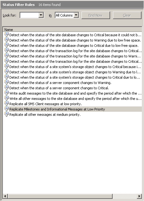
You can configure status filter rules in the ConfigMgr console under System Center Configuration Manager -> Site Database -> Site Management -> <Site Code> <Site Name> -> Site Settings -> Status Filter Rules. As shown in Figure 5.14, two “Replicate all” status filter rules are among the rules enabled by default:
• Replicate all SMS Client messages at low priority
• Replicate all other messages at medium priority
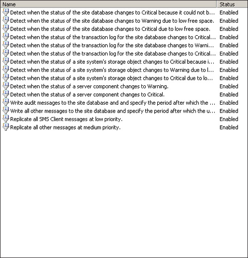
The rule to replicate client settings is higher on the list in Figure 5.15, showing that it has a higher priority and will be processed before the rule to replicate all other messages at medium priority. Messages received from clients will match the first rule and are replicated to the parent site at low priority. All other status messages will be replicated at medium priority. You can modify these rules depending on your requirements. As an example, if local administrators perform all client troubleshooting at a particular site, you may decide not to replicate status messages originating on client systems from that site to its parent site.
To stop replicating client messages, perform these steps:
- Right-click the rule.
- Choose Properties.
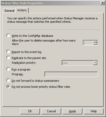
- Select the Actions tab in the Status Filter Rule Properties page.
- Tick the box at the bottom for Do not process lower-priority status filter rules.
By changing the action from Replicate to Parent Site to Do not process lower-priority status filter rules (as shown in Figure 5.15), you can prevent these messages from being processed by the lower-priority rule Replicate all other messages at medium priority. The result is that client messages will be discarded. This prevents using queries and reports at higher-level sites to view client status and deployment results.
Note that the modified rule is still named Replicate all SMS Client messages at low priority, although it no longer actually replicates the messages. To change the name of the rule, you would need to delete or disable the existing rule and create a new rule with the appropriate name. This information is also discussed in Chapter 21, “Backup, Recovery, and Maintenance.”
You can create new rules to control replication of specific types of messages. To create a new status filter rule, perform the following steps:
- Right-click the Status Filter Rules node in the console tree and then select New Status Filter Rule to initiate the New Status Filter Rule Wizard.
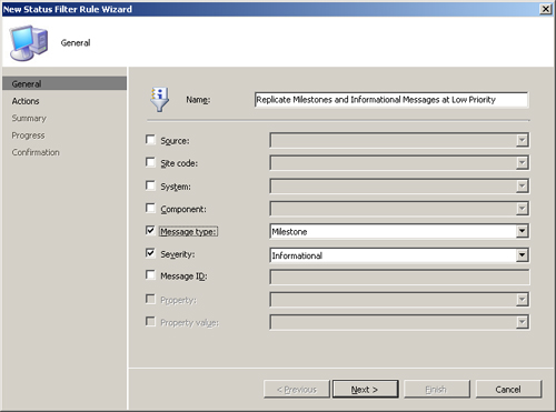
- Name the rule Replicate Milestones and Informational Messages at Low Priority and check the Message Type and Severity boxes. With the selections shown in Figure 5.16, the filter will process all messages of type Milestone or with a severity of Informational.
- Choose the action Replicate to Parent Site / Replication Priority: Low, as shown in Figure 5.17.
- The wizard will display a summary page for the new rule and ask you to confirm your choice. This completes the New Status Filter Rule Wizard.

After completing the wizard, you need to change the priority of the rule so it processes in the correct order. The rule should run after the rule that discards client messages, but before the catchall rule to replicate at medium priority.
Right-click the rule in the list and choose Increment Priority. The list of rules shown in Figure 5.18 will perform the following replication actions:
• All client messages will be dropped.
• Informational and milestone messages will be replicated only during times when the sender address setting allows sending low-priority data.
• All other messages will be replicated during times when the sender address setting allows sending medium priority data.
Figure 5.18. The list of status filter rules, including the newly created rule, in the desired order
In addition to individual status messages, each Configuration Manager site maintains status summary data. Status summary data displays the overall status of a system, component or advertisement as OK, Warning, or Critical based on the number and type of messages received. Similar to individual status messages, you can decide whether to replicate status summary data to the parent site and the data priority to assign to the replication. Chapter 21 includes the steps to configure replication of status summarizer data.
Whereas network traffic between sites is compressed, traffic within a site is not compressed. You should consider the advantages of compression, scheduling, and data priorities when deciding whether to place secondary sites at remote locations. You may want to use a secondary site to provide services that otherwise are provided by site systems belonging to the parent site, particularly distribution points. Planning for secondary sites is discussed further in Chapter 6.
Some Configuration Manager services such as software distribution can consume substantial network bandwidth.
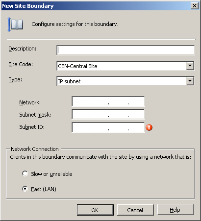
Effectively delivering these services across slow, congested, or unreliable network segments requires careful planning. ConfigMgr provides a mechanism to help with this by defining each site boundary as Fast (LAN) or Slow or unreliable, as shown in Figure 5.19.
Chapter 6 discusses site boundaries. If you are familiar with SMS 2003, you can think of fast site boundaries as SMS 2003 local roaming boundaries, and you can think of slow or unreliable site boundaries as remote roaming boundaries. Options are available to control the way in which software distribution and software updates take place, based on whether you have designated the client’s network location as fast or slow in the site boundary properties.
As an example, an advertisement or software updates deployment might specify that clients on a fast network will run the program directly from the distribution point, whereas clients on slow networks will download the files from the distribution point and run them locally. The “download and run” option allows the client to take advantage of the BITS protocol (described in the “Use of BITS” section of this chapter). You can also configure advertisements and deployments not to run at all on slow or unreliable networks. For more information about software distribution and software updates, see Chapters 14 and 15.
Fast, slow, reliable, and unreliable are all relative terms. Although the UI (user interface) suggests that a fast network shares a local area network segment with the ConfigMgr site systems, you should take this suggestion as a general guideline and not necessarily a definitive criterion. You should base your decision of whether to define a particular boundary as fast or slow on your software distribution model and how you want clients within that boundary to behave within that model. In addition to overall speed and reliability, factors you might consider include the following:
• Available bandwidth, including peak usage times
• Potential impact of software distribution on other business processes sharing the link
• The business value of delivering the higher level of service you intend to provide to fast network clients
For example, the SCCMUnleashed organization supports small office and home office (SOHO) users, some of whom have very slow and unreliable connections to the corporate network. It is essential that these users receive critical security updates and other ConfigMgr services. However, it is not feasible to distribute large software packages to them across these network connections. For this reason, many advertisements will be configured not to run on slow networks.
SCCMUnleashed has a major office and data center in Houston, and a smaller office in nearby Conroe. Conroe does not have a datacenter with server class hardware, physical security, or other services. The company decides not to deploy site systems in Conroe and to make this office part of the Houston site. The Conroe office has a 4Mbps dedicated link to Houston, which is lightly utilized. The network team uses Resource Reservation Protocol (RSVP) to guarantee an acceptable quality of service across this link for critical business processes, so the company is not concerned about the impact of software distribution on these processes. The company therefore decides to designate the Conroe subnet as a fast boundary to allow users at that site to access all advertised packages from the distribution point in Houston, even though the connection is substantially below local area network (LAN) speed. Figure 5.20 shows the Houston site.

The Background Intelligent Transfer Service optimizes file transfers based on network conditions. This optimization includes the following:
• Automatically adjusting the rate of the transfer, based on available bandwidth
• Suspending and resuming transfers that are interrupted
• Providing rudimentary consistency checking
• Using group policy and the Configuration Manager console to provide options for tuning BITS-enabled transfers
Let’s now look in depth at the BITS feature set, its use by ConfigMgr, and configuring BITS background transfers.
Configuration Manager makes extensive use of BITS to efficiently use network bandwidth and deal with network connections that are unreliable or not always available. BITS supports downloads over both HTTP and HTTPS. SMS 2003 took advantage of BITS for downloading software from distribution points to clients. Use of BITS in Configuration Manager 2007 has increased and is integral for copying data to branch distribution points, which use BITS to download and cache software packages from other distribution points. BITS 2.0 or higher is a required ConfigMgr component. Here are the key features of all BITS versions:
• File transfers that occur quietly in the background, using only bandwidth that is not required by other applications
• The ability to suspend and resume transfers interrupted by transient network conditions
BITS has been a component of all Windows operating systems since Windows XP, and it is available for Windows 2000. Microsoft has released several versions of BITS, with added functionality in each revision. The versions supported by Configuration Manager 2007 include the following:
• BITS Version 2.0—Supported for backward compatibility with systems running Windows 2000 Service Pack (SP) 4. Windows 2000 clients with earlier versions of BITS are upgraded to version 2.0 during client installation.
• BITS Version 2.5—Installed on all clients which support that version during client installation unless the client already has version 2.5 or higher. BITS 2.5 or higher is included on all systems running Windows Server 2008, Windows Vista, and Windows XP Service Pack 3. Version 2.5 can also be installed on machines running Windows Server 2003 SP 1 or SP 2 or Windows XP SP 2.
• BITS Version 3.0—Available on the Windows Server 2008 and Windows Vista operating systems only.
BITS versions 2.0 and 2.5 are available as separate downloads. Because BITS upgrades require a reboot, you may want to consider deploying the required BITS versions in advance to all clients needing an upgrade, to avoid a required reboot during ConfigMgr client deployment.
Tip
Advantage of Using Background Transfers
If you have ever initiated a large file transfer and had your computer come to a crawl, you will appreciate the concept of background transfers. BITS versions 1.0–2.0 used counters from the network interface card (NIC) to determine demand for bandwidth by other applications running on the local machine. All versions of BITS throttle the bandwidth used, such that file transfers will only take bandwidth not used by other applications. Foreground applications therefore remain responsive to the user and other services are able to operate without interruption. The transfers occur asynchronously, meaning that the rate can vary over time.
Instead of a steady stream of data, you can consider the data as being “drizzled” across the network. This also allows a transfer that is interrupted to pick up where it left off when connectivity is restored.
One problem with earlier versions of BITS is that the system is only aware of the traffic passing through the NIC. Even if the network segment to which the machine is connected is quite congested, if there is little or no network activity on the local machine it would appear to BITS that most of the bandwidth supported by the card is available. Under these conditions BITS transmits data at a high rate, potentially causing additional network congestion problems. BITS 2.5 and higher versions get around this limitation by pulling usage statistics from the Internet Gateway Device (IGD). Certain conditions must be met in order to pull statistics from the IGD:
• Universal Plug and Play (UPnP) must be enabled.
• The device must support UPnP byte counters.
• UPnP traffic (TCP 2869 and UDP 1900) is not blocked by any firewall device or software.
• The device must respond to GetTotalBytesSent and GetTotalBytesReceived in a timely fashion.
• The file transfer must traverse the gateway.
Note
Error 16393 if BITS Cannot Retrieve Information from IDG
If BITS is unable to retrieve counter data from the IDG, the following event is logged:
Event ID 16393 Source: Microsoft-Windows-Bits-Client
BITS has encountered an error communicating with an Internet Gateway Device. Please check that the device is functioning properly. BITS will not attempt to use this device until the next system reboot. Error code: %1.
In most circumstances, BITS will intelligently manage the use of network bandwidth without additional configuration. If you find that BITS-enabled transfers are consuming more bandwidth than desired or if you want to provide extra protection for other business-critical network activity, group policy can limit the bandwidth BITS will consume. The setting is specified in Kbps, and its name varies depending on the version of Windows you are running.
• For Windows Server 2003 group policy, the setting is called “Maximum network bandwidth that BITS uses.”
• For Windows Server 2008 group policy, the setting is “Maximum network bandwidth for BITS background transfers.”
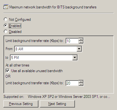
In both versions of Windows Server, this setting is found under Computer Configuration -> Administrative Templates -> Network -> Background Intelligent Transfer Service. The setting, shown in Figure 5.21 for Windows Server 2008 group policy, allows a limit for a specific time interval (such as working hours) and a different limit for outside that interval. All versions of BITS supported by ConfigMgr also have a timeout for inactive transfers (defaulting to 90 days) that is configurable through group policy.
BITS 3.0 introduces several new group policy options. These allow you to control settings such as the maximum active download time for BITS jobs, the number of jobs allowed per user and per machine, and the maximum number of files per job.
Group policy settings are only available in Active Directory domains. Although group policies are generally applied at the domain or Organizational Unit (OU) level, BITS-related policies are examples of a policy that you might consider implementing at the site level.
An AD site is generally a region of high network connectivity. By applying the BITS-related policies to the site, you can control the behavior of all systems in your AD forest based on network location, regardless of their domain or OU membership.
You can also define the maximum network bandwidth for BITS background transfers using the ConfigMgr console. The settings are specified on the BITS tab of the Computer Client Agent property sheet, located under System Center Configuration Manager -> Site Database -> Site Management -> <Site Code> <Site Name> -> Site Settings -> Client Agents -> Computer Client Agent - > BITS tab on the Configuration Manager console. As shown in Figure 5.22, these settings are similar to the group policy settings, but in this case they are applied either to all clients in the ConfigMgr site or to branch distribution points only.
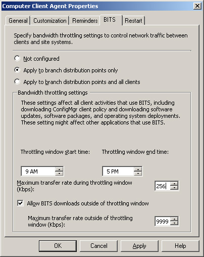
Unlike group policy settings, the settings on the Computer Client agent apply to clients that are in workgroups or untrusted domains. These are global settings for all clients in the site, however, while group policy allows you to control the behavior of BITS for clients in specific domains, OUs, individual computers, or AD sites. You can achieve even more granular control of group policy by WMI filtering and/or security group filtering. These filtering techniques selectively apply group policy objects (GPOs) to users or computers based on the results of WMI queries or security group membership. An excellent resource on group policy management is available online at the Windows Server 2003 Tech Center (http://technet2.microsoft.com/windowsserver/en/library/):
• The section on WMI filtering is found at http://technet.microsoft.com/en-us/library/cc779036.aspx.
• Security group filtering is discussed in http://technet.microsoft.com/en-us/library/cc781988.aspx.
Tip
Group Policy Management References
For your convenience, these URLs are included as live links in Appendix B, “Reference URLs.”
As mentioned earlier in the “BITS Versions for Configuration Manager Clients” section of this chapter, Windows Server 2008 group policy has a wider range of BITS-related options for BITS version 3.0 than that available through the ConfigMgr settings. Through ConfigMgr, however, you are able to assign BITS settings specifically to branch distribution points. Because there are different options available through group policy and ConfigMgr settings, you may choose to use both to control BITS behavior.
Caution
Avoid Conflicts in Group Policy and ConfigMgr BITS Settings
If you are using both group policy and ConfigMgr settings to govern BITS functionality, be careful to avoid applying both methods to the same systems. The domain policies will override locally stored ConfigMgr settings and may produce unpredictable results. If systems requiring ConfigMgr BITS settings reside in AD containers that have BITS policies applied, you can use WMI filtering or security group filtering to block application of group policy objects containing BITS settings. In any case, you should plan and test such configurations carefully.
On client systems with multiple physical or virtual interfaces, BITS uses the GetBestInterface function to select the interface with the best route to the server it needs to access. Once the file transfer is complete, BITS verifies that the file size is correct. However, BITS does not perform a more extensive file integrity check to detect corruption or tampering that may have occurred.
In order to enable a distribution point to use BITS, the distribution point must be running IIS 6.0 or higher with ASP.NET and WebDAV (Web-based Distributed Authoring and Versioning) enabled. You can enable these features in various ways, depending on the version of Windows Server you are running. After meeting these prerequisites, you can enable a distribution point for BITS through a check box on the distribution point properties page, as shown in Figure 5.23. Note that BITS-enabled distribution points will download files to clients and branch distribution points using BITS; however, programs that run from the distribution point will use the standard SMB protocol.

To optimize Configuration Manager’s use of your network, you should consider the placement of servers holding various site roles. The following guidelines should help with your planning:
• The site server should have a high bandwidth and highly available connection to the site database server. The site server also needs good connectivity to a domain controller, particularly if any of the Active Directory discovery methods are enabled.
• You can install the SMS provider on the site server, the site database server, or another server with highly available network connectivity to these systems and to all systems running the ConfigMgr console. Because the SMS provider uses system and network resources, you should consider the resources available when you select the provider location. For more information on choosing the provider location, see http://technet.microsoft.com/en-us/library/bb694290.aspx.
• The reporting point needs good connectivity to the site database server.
• You can configure the management point and server locator point to use the site database or a replica of the site database. In either case, good connectivity to the database is required.
• You should place all client-facing systems in close proximity to the clients they serve. If you support Internet-only clients, the systems these clients will access should be in a DMZ (demilitarized zone, also known as a perimeter network). In general, do not place the site server and site database server in an Internet-accessible DMZ.
• The placement of distribution points is especially important. For clients across a WAN link from the site server, consider whether to deploy a standard distribution point or a branch distribution point.
A branch distribution point uses BITS to receive packages across the WAN but requires clients to use SMB. A standard BITS-enabled distribution point uses SMB across the WAN, but is capable of providing BITS downloads to clients:
• A small office with a few clients separated from the main site location by a slow or unreliable link is an excellent candidate for a branch distribution point.
• For a larger office with a better WAN connection, you should consider a standard protected distribution point. Standard distribution points provide the advantage of allowing clients to download content using BITS. You may still decide to deploy a branch distribution point at a larger site to take advantage of “on-demand” package distribution. Another advantage of branch distribution points is you can use OOB methods such as copying files from a local source to distribute a package to a branch DP, avoiding the WAN link altogether. If you install branch distribution points at larger sites, you should place them on systems running a server operating system to avoid the connection limitations of Windows Vista or Windows XP.
• You may also decide to deploy a secondary site at the remote location to take advantage of intersite communication features such as scheduling and compression, or to provide additional site server roles such as a proxy management point or software updates point. Determining when to create additional sites is discussed in Chapter 6.
Users who do not connect to the enterprise network or who only connect occasionally present a special configuration management challenge. SMS 2003 provided limited support for intermittent network connections through BITS. When a client’s network connection to its distribution point dropped while a download was in progress, the download could resume the next time the client established a connection to that distribution point. This allowed effective software distribution services to users such as home office users who intermittently establish a VPN connection to the corporate network. Those individuals using laptops both at the office and away from the office also benefit from the ability to resume interrupted downloads.
However, for some highly mobile users it is unlikely to complete a large download efficiently using a single distribution point. Airline pilots, for example, may carry laptops that they use to connect to the airline’s network at various airports along their route. Each airport is likely to fall within the boundaries of a different site or distribution point. A suspended download would therefore start over from the new distribution point and might never complete. A Configuration Manager 2007 enhancement allows suspended BITS downloads to resume from any BITS-enabled distribution point. In this way, pilots and other highly mobile users are able to complete downloads as they travel.
Configuration Manager also provides Internet-Based Client Management (IBCM), which allows you to provide some services to users who never connect directly to your network. IBCM allows you to provide services over the Internet, including software distribution and software updates to Internet-only clients. You will also receive inventory and status from those clients. Clients that sometimes connect to the corporate network can also take advantage of IBCM services, including the ability of BITS downloads to take place partially over the intranet and partially over the Internet. IBCM does not support OS deployment, client deployment, NAP, and ConfigMgr Remote Tools. For more information on Internet-based clients, see Chapter 12.
Configuration Manager can use a variety of network protocols to probe your network and gather data about the objects it discovers into the site database. Network discovery can be used to identify potential ConfigMgr clients. Network discovery can also be used to add network topology data and information about non-client network devices to your database for use in queries, collections, and reports. Configuration Manager network discovery is similar to that in SMS 2003, except there is a new configuration tab for DHCP servers and support added for IPv6.
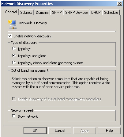
To configure network discovery, right-click Network Discovery in the Configuration Manager console under System Center Configuration Manager -> Site Database -> Site Management -> <Site Code> <Site Name> -> Discovery Methods -> Network Discovery and then choose Properties. As displayed in Figure 5.24, there are three levels of network discovery:
Note
About Network Discovery Resource Utilization
Network discovery can have a major impact on your network and site systems. To avoid overloading network or server resources, you should schedule network discovery to run during off-peak times. If you have a large number of machines, you should perform initial discovery in phases. You may choose to discover a few subnets at a time or you may choose to first discover topology only, then clients, and later add operating system discovery. You should limit the number of new resources you expect to discover to no more than 5,000 at a time.
If discovery will traverse slow network segments, check the Slow network box on the General tab to throttle the number of concurrent network request and adjust timeout values.
The Subnets, Domains, and SNMP Devices tabs determine the initial scope of network discovery. Figure 5.25 displays the Subnets tab. By default, the local subnet and the site server’s domain will be discovered. You can add subnets, domains, or SNMP devices using the starburst icon (circled in Figure 5.25) on the respective tabs. You can also remove or modify existing subnets or domains.

Network discovery uses Simple Network Management Protocol (SNMP) to query network infrastructure devices for basic information about your network topology. The discovery process generates data discovery records (DDRs) for network devices and subnets. A DDR is a small file with identifying information about an object that is processed and stored in the ConfigMgr database. The properties for SNMP discovery are configured on the SNMP tab of the Network Discovery Properties sheet, shown in Figure 5.26.

All SNMP devices are configured with a community string, which by default is named public. To connect to an SNMP device, you must add its community string to the list of communities to discover. The maximum hops specified on the SNMP tab controls how far discovery will traverse the network. If the number of hops is set to 0, the devices on the site server’s local subnet will be discovered. If the number of hops is more than 0, network discovery will query the routing tables of the local router to retrieve a list of subnets connected to it and the IP addresses of devices listed in the ipRouteNextHop of the router. These subnets and devices are considered to be one hop away. Network discovery will continue to perform the same process based on the routing data of the devices on the next hop, until it reaches the maximum number of hops. Additional subnets and devices on those subnets will be discovered if one of the following occurs:
• The subnet is specified on the Subnets tab.
• The subnet information is retrieved from a device specified on the SNMP Devices tab.
Because a router can be connected to many subnets, the scope of network discovery can increase dramatically with each higher value of the Maximum hops setting. On the local subnet, network discovery can connect to the router using Router Information Protocol (RIP) or by listening for Open Shortest Path First (OSPF) multicast addresses, even if SNMP is not available on the router.
Network discovery can also retrieve information from Microsoft DHCP servers. The Network Discovery Properties DHCP tab lists the DHCP servers to query. By default, network discovery will use the site server’s DHCP server, although typically, the site server is not configured as a DHCP client and you will need to add DHCP servers manually using the starburst icon. Figure 5.27 displays an example of this.

The site server will establish an RPC connection to each of the specified DHCP servers to retrieve subnet and scope information. Subnets defined on the DHCP servers are added to the list of available subnets for future network discovery, but are not enabled for discovery by default. For each active lease on the DHCP server, the network discovery process also attempts to resolve the IP address to a name. For more information on Microsoft DHCP, see the Microsoft DHCP FAQ at http://www.microsoft.com/technet/network/dhcp/dhcpfaq.mspx#EUG.
To discover potential Configuration Manager clients, network discovery attempts to identify as many devices as possible on the IP network. An array of IP addresses from the ipNetToMediaTable of SNMP devices is used to identify IP addresses in use, and network discovery pings each address to determine if it is currently active. If the device replies to the ping, network discovery attempts to use SNMP to query the device. If network discovery can access the device’s management information through SNMP, it will retrieve any routing table or other information the device holds about other IP addresses it is aware of. Each IP address is resolved to a NetBIOS name if possible.
Network discovery will also retrieve the Browse list for any domains specified on the Domains tab. The Browse list is the same list used to display machines in the Windows Network Neighborhood, and can be enumerated with the Net View command. As with other discovered devices, network discovery then attempts to ping the device to see if it is active.
In addition to the discovery process for topology and clients, if client operating system discovery is specified, network discovery will attempt to make a connection using LAN Manager calls to determine whether the machine is running Windows and, if so, what version of Windows it is running.
In order for network discovery to create a DDR for a discovered device, the IP address and subnet mask of the device must be retrieved. Network discovery retrieves the subnet mask from one of the following:
• The device itself if it is manageable through SNMP— Windows machines are only manageable through SNMP if the SNMP service is running and configured with the required community information. This will generally not be the case.
• The Address Resolution Protocol (ARP) cache of a router with information about the device— ARP is a protocol used to resolve IP addresses to the Media Access Control (MAC) addresses of the network cards. Routers keep this information cached for a finite amount of time, depending on the router configuration. The ARP cache generally will not have information about every device on the attached network segment. This makes retrieving subnet mask information from the router ARP cache a hit-or-miss operation.
• The DHCP server— If you are using Microsoft DHCP for all of your IP address assignment, retrieval of subnet mask information from the DHCP server will generally work well. Any machines with static IP addresses or any machines using non-Microsoft DHCP will need to be discovered by another method. All DHCP servers must also be listed on the DHCP tab.
There are many dependencies for network discovery to work properly. Required protocols must be allowed by firewalls, enabled, and configured properly on clients. Network discovery is an important way to discover clients, but in general you will not want to rely on it exclusively. Client discovery methods and strategies are discussed in Chapter 12. In addition to discovering potential clients, network discovery provides information about your network environment that is not available from other discovery methods.
The boundaries of Configuration Manager sites and protected site systems determine the network locations from which clients can receive certain services from the site or system. Site boundaries are defined as follows:
• An Active Directory site
• An IP subnet
• An IP range
• An IPv6 prefix
You select boundaries for protected site systems from the boundaries of the site.
Active Directory sites generally correspond to a local area network. By using AD sites as site boundaries, you may be able to eliminate the duplication of effort involved in maintaining subnet information in two places. You should update the AD site configuration to reflect network topology changes, such as adding new subnets to a LAN. As long as the site structure in AD is appropriate for your ConfigMgr sites, relying on AD sites as boundaries will be a simple and effective solution.
In some cases, you may need more granular control of your site boundaries. For example, you may wish to add satellite offices to a ConfigMgr site that are not part of the same AD site. You may also want to provide a separate Configuration Manager site for particular types of systems within your AD site, such as servers. You may also need to use IP-based boundaries to support clients that are not able to retrieve site information from your Active Directory, such as workgroup clients or clients in domains that do not have a trust relationship with your site server’s domain.
Protected site systems are useful for smaller offices that do not have their own Configuration Manager site but have local servers that can provide services to clients. The site systems that can be protected systems are distribution points and state migration points. Clients within the boundaries of a protected system will use that system before using another distribution point or state migration point in the site.
In SMS 2003, a client within the boundaries of a protected distribution point would use only the protected distribution point to access package content. In Configuration Manager 2007, you can specify whether the client will use another distribution point if content is not available from the protected distribution point. This behavior is specified through options in the properties of the advertisement, software update deployment, or task sequence. Advertisements, software update deployment, and task sequences are discussed in Chapters 14, 15, and 19, respectively.
Configuration Manager depends on basic network services such as connectivity and name resolution to work properly. Network-related issues are a common source of problems that can affect Configuration Manager service delivery. The next sections look at some typical issues you may encounter related to network dependencies. When troubleshooting, it is important to keep an open mind. Some issues caused by incorrect security settings, for example, can produce very similar symptoms to network issues. The last part of this chapter provides a brief overview of some general network troubleshooting methods, followed by a discussion of how to troubleshoot some specific ConfigMgr issues potentially caused by network problems.
Among the common network-related issues that can affect Configuration Manager are the following:
• Network configuration issues
• Basic connectivity problems
• Name resolution issues
• Blocked or unresponsive ports
• Timeout issues
The following sections briefly describe a few of the many tools and techniques for troubleshooting these types of issues.
If you suspect that the TCP/IP networking on one of your systems is not working correctly, you can log on to the system and enter the following at the command prompt (Start -> Run, and then type cmd):
Ipconfig /all
You should see a list of the installed network adapters with IP addresses and other IP configuration data. If no IP address or only an autoconfiguration IP address is displayed, the network components are either not configured or not functioning properly. If this occurs when the IP address configuration is set to obtain an IP address automatically, this means the machine was unable to contact a DHCP server. For more information on configuring TCP/IP, see http://technet2.microsoft.com/windowsserver/en/library/99f79ed8-df1e-49a6-a4f4-eb13623663011033.mspx?mfr=true.
If the machine has one or more valid IP addresses, you can test TCP/IP functioning by entering the following two commands at the command prompt:
• Ping 127.0.0.1
• Ping <IP address of this machine>
In both cases, you should see a series of replies, such as the following:
Reply from 127.0.0.1: bytes=32 time=9ms TTL=128
If you receive a request timed out message, TCP/IP networking on the machine is not working properly.
The NetDiag.exe utility, which you can download from Microsoft’s website, can be used to diagnose (and in some cases fix) a wide variety of network configuration issues. For more information on Netdiag, see http://www.microsoft.com/technet/prodtechnol/windows2000serv/reskit/prork/pref_tts_nigx.mspx?mfr=true.
Basic connectivity problems occur if
• Systems are not physically connected;
• There is a hardware or software problem on one of the systems or an intermediate device;
• The packets are not correctly routed between the systems.
To start troubleshooting basic connectivity, log on to one of the affected systems and ping the system with which it has problems communicating. To do this, open a command prompt (Start -> Run, and then type cmd) and enter the following command:
Ping <IP address of target system>
In most cases, you should get a response showing the time it took to get a reply to the ping request and other statistics. If the system is not responding, you may get one of the following messages:
• Request timed out—
This simply means that you did not get a response in the expected time. In some cases, the target system may have been configured not to respond to a ping. You can test this on the target system by pinging its own IP address to make sure it is responding. If you suspect that the ping request timed out because of slow network conditions, you can try increasing the timeout value from the default value of 1 second. As an example, Ping -w 5000 <IP address of target system> will wait 5,000 milliseconds (5 seconds).
• Destination Host Unreachable or Destination Network Unreachable— This is generally a response from a router indicating that no route is defined to the host or subnet.
Other return values are possible indicating specific errors. For more information on the ping command, see http://technet2.microsoft.com/windowsserver/en/library/9eaf7bddee42-4358-9b60-66c8463dbdee1033.mspx?mfr=true.
You can drill deeper into connectivity issues using commands such as tracert and pathping, which are described at http://www.microsoft.com/technet/prodtechnol/windows2000serv/reskit/cnet/cnbd_trb_dfln.mspx?mfr=true.
Most Configuration Manager components rely on DNS for name resolution. In some cases, ConfigMgr also uses NetBIOS name resolution. Once again, you can use the ping command as a quick test of name resolution. At the command prompt, enter
• Ping <FQDN of target system>
For example:
Ping bluebonnet.sccmunleashed.com
• Ping <hostname of target system>
For example:
Ping bluebonnet
• Ping <NetBIOS name of target system>
For example:
Ping \bluebonnet
In each case, these commands should return a response showing the correct IP of the target system, such as the following:
Pinging bluebonnet.sccmunleashed.com [192.168.5.4] with 32 bytes of data:
If DNS name resolution fails, you can troubleshoot this using the NSlookup command described at http://support.microsoft.com/kb/200525. To troubleshoot NetBIOS name resolution using Nbtstat and other methods, see KB article 323388 (at http://support.microsoft.com/kb/323388). It’s also useful to test pinging the known IP address of the target machine—if that works then you have narrowed the issue to some sort of name resolution–related issue.
An additional DNS problem that sometimes occurs is an incorrect referral. Incorrect referrals occur when a hostname is used instead of an FQDN, and the wrong domain name is appended due to the DNS suffix search order. This typically results in “access denied” errors. If you see unexpected “access denied” errors, try pinging the site system using both the hostname and the FQDN to make sure they resolve to the same address.
A common source of connectivity problems involves ports blocked by intermediate devices such as routers or firewalls. In other cases, the port may simply not be listening on the system to which you are trying to connect. To identify problems with specific ports, first refer to Table 5.1 earlier in this chapter to determine the ports used by the failing service. You can then attempt to connect to the specific port on the target system using the telnet command. For example, to verify that you can connect to the Trivial File Transfer Protocol (TFTP) Daemon service (port 69) on PXE service point Dabney.SCCMUnleashed.com, open a command prompt (Start -> Run, and then type cmd) and enter the following:
Telnet Dabney.SCCMUnleashed.com 69
If telnet is successful, you will receive the Telnet screen with a cursor. If the connection fails, you will receive an error message.
When a connection to a port fails, first verify that the service is listening on the appropriate port. On the machine that should receive the connections, enter the command netstat –a to list all connections and listening ports.
• If the port is not shown, verify that all system requirements and prerequisites are met.
• If the port displays as enabled, check all network firewall logs for dropped packets.
Refer to your network team or vendor firewall documentation for procedures for checking firewall logs. Also, check the Windows Firewall logs and settings (see http://technet.microsoft.com/en-us/network/bb545423.aspx) and any third-party security software that performs intrusion detection and prevention.
Additional tools are available for troubleshooting port status issues, such as the following:
• The PortQry command-line utility, downloadable from http://www.microsoft.com/downloads/details.aspx?familyid=89811747-C74B-4638-A2D5-AC828BDC6983&displaylang=en.
• PortQryUI, which you can download from http://www.microsoft.com/downloads/details.aspx?FamilyID=8355E537-1EA6-4569-AABB-F248F4BD91D0&displaylang=en. PortQryUI provides equivalent functionality to PortQry through a graphical user interface (GUI).
Going to www.microsoft.com/downloads and searching for PortQry will bring up links for both these tools.
The response times you see from the ping command can help you to confirm network performance problems that could be causing connections to time out. In some cases timeouts are configurable; however, if timeouts are a frequent problem, you should review your server placement and network configuration to see if improvements can be made.
Almost all Configuration Manager functionality depends on adequate network services. The next sections will look at some of the features most often affected by network issues. These features include site system and client installation, software distribution, and data synchronization across the hierarchy. Chapter 3 introduced the two major features of Configuration Manager for troubleshooting:
• The Status Message System
• The ConfigMgr logs
The following sections discuss some indicators of possible network issues that you may see in the status messages and logs. In addition to troubleshooting, you can use this information to configure proactive monitoring for ConfigMgr, helping to spot many problems before they impact service delivery.
The following discussion is by no means an exhaustive list of possible network issues. It does cover some of the more common issues, and should give you an idea of how to use these tools effectively.
When there is a problem installing or configuring a site system, this will generally show up in the Site Component Manager status. In the ConfigMgr console, expand System Center Configuration Manager -> Site Database -> System Status -> Site Status -> <Site Code> <Site Name> -> Component Status. Right-click SMS_SITE_COMPONENT_MANAGER and choose View Messages -> All. If network problems are preventing a site system installation, you will typically see status messages similar to the ones detailed in Table 5.3.
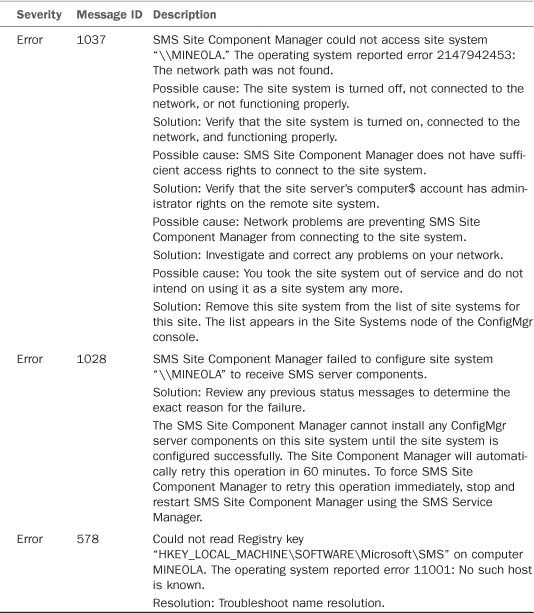
You will find additional information in the log file sitecomp.log. Network problems are indicated by errors such as ERROR: NAL failed to access NAL path....
When Client Push Installation is enabled, the Client Configuration Manager component on the site server is responsible for installing the client on those systems that are discovered and targeted for installation. When an installation attempt fails, a Client Configuration Request (.CCR) file is copied to the folder <%ProgramFiles%ConfigMgrInstallPath>inboxesccrretry.box (where <ConfigMgrInstallPath> indicates the folder in which Configuration Manager is installed, by default Microsoft Configuration Manager.
It is not unusual for a client installation to take more than one attempt, and you may see some files in the ccrretry.box folder as part of normal operations. However, a large backlog of files in this location may indicate a problem pushing out the client software. Problems will also show up under the status for Client Configuration Manager (in the console under System Center Configuration Manager -> Site Database -> System Status -> Site Status -> Component Status -> SMS_CLIENT_CONFIG_MANAGER).
Note
About Offline Clients
You may see a backlog of CCR retries and numerous status messages indicating client installation failures, which occur simply because the machines were temporarily disconnected or shut down when Client Configuration Manager attempted to contact them. The Client Configuration Manager may also be attempting to reach machines that are permanently offline but previously discovered by ConfigMgr 2007. This is a particularly common issue with Active Directory system discovery. If your Active Directory contains machine accounts for computers that no longer exist, AD system discovery will discover these machines, and Client Push (if enabled) will attempt to install the client on them. Your change control process should include removal of stale computer accounts from Active Directory.
See Chapter 21 for additional considerations for managing discovery data.
Table 5.4 lists some messages that indicate possible network issues.
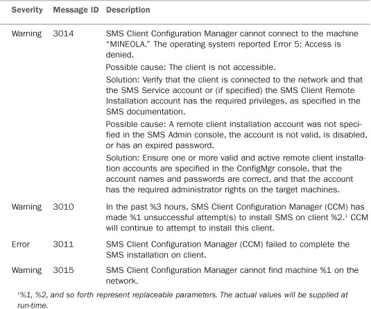
You may find additional information in the log files ccm.log on the site server and ccmsetup.log on the client (the ccmsetup log only exists if the attempted installation progressed far enough for the setup process to start on the client).
Table 5.5 lists log entries that can help identify network issues.

Service Principal Names (SPNs) provide information used by clients to identify and mutually authenticate with services using Kerberos authentication. Services use Active Directory SPN registration to make the required information available to clients. Missing or incorrect SPN registration is a common cause of problems with client communications with site systems, such as failure to download content or client approval problems. HTTP 401 errors in client log files, including the Datatransferservice.log and ccmexec.log, may indicate problems with SPN registrations. To register the required Service Principal Names properly, refer to the following documentation:
• If you are running the SQL Server service using a domain account on the site database server or other roles requiring SQL Server, you must follow the instructions in http://technet.microsoft.com/enus/library/bb735885.aspx to register the SPN. If the SQL Server service is configured to run under the local system account, you do not need to manually register the SPN. However, running SQL Server in the local system context is not recommended for security reasons.
• For site systems that require IIS, if the system is registered in DNS using a CNAME (a DNS alias rather than the actual computer name), you will need to register the SPN using the procedure described in http://technet.microsoft.com/en-us/library/bb694288.aspx.
• If you are using a management point configured as a network load-balancing (NLB) cluster in a mixed mode site, refer to http://technet.microsoft.com/en-us/library/bb735879.aspx for instructions on SPN registration.
Software distribution relies on networking to send packages to distribution points and for clients to download policy from management points and content from distribution points. Figure 5.28 shows the principal network exchanges involved in software distribution. In this figure, the directional arrows indicate the principal direction of data transfer. This may differ from the direction shown in Table 5.1, which indicates the system initiating the connection.
Figure 5.28. The major systems for software distribution and data flow between them. The client–to–management point connection includes policy downloads and status uploads.
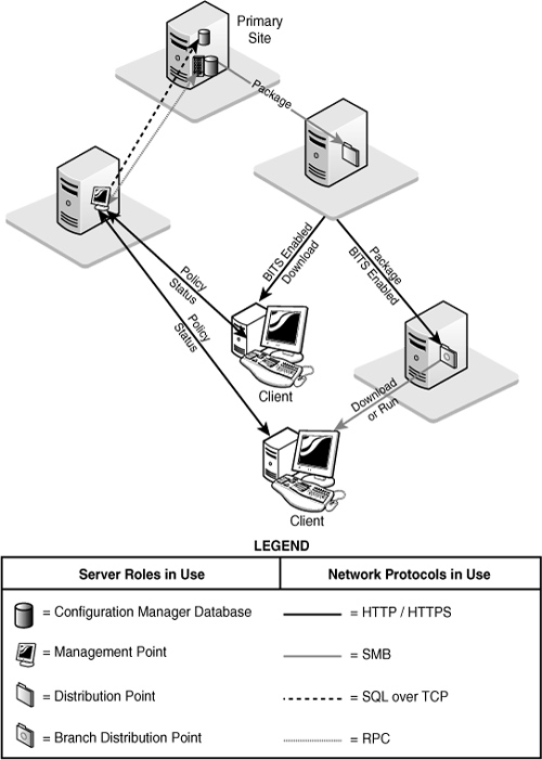
You will find status information relating to the general functioning of package deployment under System Center Configuration Manager -> Site Database -> <System Status> -> Site Status -> Component Status -> SMS_DISTRIBUTION_MANAGER.
Table 5.6 shows Distribution Manager status messages that may indicate network problems preventing package distribution. You can also find status information for individual packages under System Center Configuration Manager -> Site Database -> System Status -> Package Status. Additional details are available in Distmgr.log.
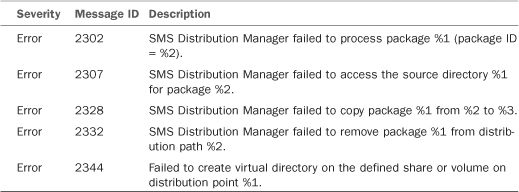
Some general status information about advertisements is available in the Configuration Manager console. General statistics about advertisements are located under System Center Configuration Manager -> Site Database -> System Status -> Advertisement Status.
To view status messages for a particular advertisement, expand out the Advertisement Status node, select the advertisement, right-click the site of interest from the right window, choose Show Messages, and then select an interval of interest. Status message ID 10051, for example, indicates that the package was not available on the distribution point. Detailed troubleshooting of advertisement problems often requires looking at the client logs.
Table 5.7 shows some key entries to check in the client logs. Client log files are discussed in Appendix A, “Configuration Manager Log Files.”
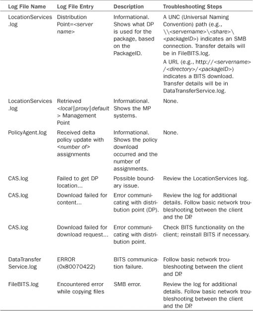
Configuration Manager provides an option to enable Network Abstraction Layer (NAL) logging, which adds detailed logging of network connection processing to the log for components that use network resources. NAL logging increases the log size substantially and logs many apparent errors that may be misleading; however, it can also be an essential tool for network troubleshooting. In general, you should only enable NAL logging when you need it to troubleshoot a specific issue. Appendix A discusses how to enable NAL logging.
Problems with site-to-site communications can cause problems such as new or modified objects at parent sites not replicated to child sites, and data from child sites not updated at the parent site. An indication of problems with site communications is often a backlog of files in the folders used by the site-to-site communications components:
• <ConfigMgrInstallPath>inboxesschedule.boxoutboxes<sender name> is the outbox for the sender (where <sender name> is the name of the sender; for the standard sender this will be LAN).
Files used by the sender are queued here for processing. A backlog of send request (.srq) files may indicate that the sender is having problems processing requests or a problem connecting or transferring data to another site.
• <ConfigMgrInstallPath>inboxesschedule.box equests stores send requests before sending them to the sender.
• <ConfigMgrInstallPath>inboxesschedule.box osend stores package and instruction files to transfer to another site.
If you find a backlog of files in any of these folders, check the sender log (sender.log) for errors. You may also view the sender status in the ConfigMgr console, under System Center Configuration Manager -> Site Database -> System Status -> Site Status -> Component Status -> SMS_LAN_SENDER.
This chapter described how Configuration Manager 2007 uses the network. It discussed the protocols used by Configuration Manager as well as configuring the network components. It then considered how you could apply this knowledge to optimize your network utilization and server placement. The chapter looked at some of the details of BITS, a key enabling technology for Configuration Manager, and described how Configuration Manager network discovery can gather data about network resources and potential clients. Finally, it discussed network troubleshooting, and ways to identify network issues that may affect some specific Configuration Manager components and services.
The next chapter describes how to plan your Configuration Manager infrastructure, with a special emphasis on specific new features that present infrastructure planning challenges.