
IN THIS CHAPTER
This chapter discusses a number of technologies used in Configuration Manager (ConfigMgr) 2007. These include the significance of certificates and their use in ConfigMgr 2007, with some basic information that will help when troubleshooting communication issues within the hierarchy. The chapter also reviews the technologies associated with Network Access Protection (NAP), specifically Windows Server 2008 and its Network Policy Server role. It then moves into the area of operating system (OS) deployment technologies, reviewing ImageX and associated technologies. The chapter also discusses Intel’s Active Management Technology (AMT), its relationship with vPro, and ConfigMgr’s Out of Band Management capabilities, introduced with ConfigMgr 2007 Service Pack (SP) 1. You will learn how these technologies work, how they complement Configuration Manager, and best practices to leverage these OS deployment tools.
Although none of these technologies is required to implement a ConfigMgr site, having a good understanding will only help ConfigMgr administrators when implementing these features and functionality. Here are the key ConfigMgr capabilities these technologies support:
• Operating System Deployment, known as OSD
• Internet-based client management, known as IBCM
• Out of Band (OOB) Management, which allows an administrator to connect to a computer when the system is turned off, in sleep or hibernate mode, or otherwise unresponsive through the operating system
OSD and IBCM provide ConfigMgr administrators the capability to create huge amounts of return on their investment in ConfigMgr licensing and its overall cost in implementation and administration. In other words, if you are not utilizing these two capabilities, you will want to look into them extensively—you will be upgrading Windows at some point, and clients are more mobile now than ever before. Either of these ConfigMgr capabilities can save your organization considerable money. OOB enables remote administration of client systems that were previously inaccessible due to the new management standards and technologies.
You can implement ConfigMgr in either mixed mode or native mode. Native mode, the more secure of the two, requires several certificates from the PKI (Public Key Infrastructure) for it to handle operations such as IBCM. A PKI is an implementation of certificate technology that allows binding a public key with some identity via a Certificate Authority (CA). ConfigMgr leverages the PKI to encrypt the transmission of data between the management point (MP) and the client itself, and authentication of the client to the MP. For ConfigMgr, these identities are machine accounts. The certificate is bound via a registration process and then carried out by Active Directory group policy objects (GPOs) and the CA auto-enrollment process. You can also implement the certificates manually, depending on your environment and deployment processes. ConfigMgr does not perform any of the certificate deployment or management for the PKI or itself; the PKI’s Registration Authority ensures the certificates are correctly bound. Each account, identity, public key, binding, and validity condition allow the CA to generate and issue certificates that cannot be duplicated.
Note
ConfigMgr PKI Requirements
ConfigMgr 2007 can only leverage template-based certificates issued by an enterprise Certificate Authority running on the Enterprise edition or Datacenter edition of Windows Server 2003 or Windows Server 2008. Running a PKI on the Standard edition of Windows Server 2003 or 2008 does not give administrators the ability to modify the templates per ConfigMgr’s requirements.
Microsoft specifies certificate requirements for native mode at http://technet.microsoft.com/en-us/library/bb680733.aspx. Unfortunately, this topic was not well documented in the base release (also known as Released-to-Manufacturing [RTM]) of ConfigMgr 2007, and many administrators struggled trying to get PKI certificates to work while the CA was running on Windows Server 2003 Standard edition.
Cryptography is the practice of hiding information, commonly used in security scenarios such as ATM cards and passwords. Two cryptographic functions are supported:
• Symmetrical encryption
• Asymmetrical encryption
Encryption is the process of transforming information (referred to as plain text) using an algorithm (a cipher) to make it unreadable to anyone except those possessing special knowledge, usually referred to as a key. The result of the process is encrypted information (referred to as cipher text in cryptography). In many contexts, the word encryption also implicitly refers to the reverse process, decryption (such that “encryption software” will also perform decryption), that is, to make the encrypted information readable again by making it unencrypted.
Symmetrical encryption uses a single key for encryption, which both the sender and receiver will leverage to decrypt the transmissions. When data is encrypted with a symmetric algorithm, the sender generates a random symmetric key. The algorithm and the application determine the bit-length of the key. Figure 11.1 illustrates the symmetrical encryption process.

Asymmetric encryption uses a key pair. The keys that make up the key pair are mathematically related and referred to as the public and private keys. Public keys are distributed freely. You can publish them to Active Directory (AD) and install them via auto-enrollment. The “Deploying Certificates” section of this chapter covers auto-enrollment. The use of this key pair ensures that only the recipient has access to the necessary private key to decrypt the data. Figure 11.2 illustrates the asymmetrical encryption process.

The following points define the process illustrated in Figure 11.2:
- The sender obtains the recipient’s public key.
- Data is passed an asymmetrical encryption algorithm. It is encrypted with the recipient’s public key, producing encrypted cipher text.
- Cipher text is sent to the recipient, who already has the private key.
- The recipient decrypts the cipher text with his or her private key back into the original format.
Note
Using Symmetric and Asymmetric Encryption
Applications will generally use both encryption algorithms to encrypt data by first encrypting the data with a symmetric algorithm and then encrypting the symmetric encryption key using an asymmetric algorithm.
Two inputs are required when encrypting data:
• The algorithm
• The key
The algorithm defines how to convert the data to the cipher text, and the key is used to input the data into the algorithm. Figure 11.3 illustrates the asymmetrical signing process.

The following steps demonstrate how in Figure 11.3 you can validate the sender’s identity and that the data was not altered:
This encryption process protects the data, or payload, from being intercepted and read, viewed, or altered. If it were intercepted, the decryption process would fail, thus letting the recipient know there was a breach.
Digital signing is used to prove the source and integrity of the data. Using a hash algorithm, digitally signed data can be trusted to be the original content. Hash algorithms such as MD5 (Message Digest 5) and SHA1 (Secure Hash Algorithm 1) apply a mathematical formula to an object, resulting in output known as a hash value, message digest, or just digest. Hashes cannot be reversed, making them very useful in verifying data integrity.
Refer to Chapter 6, “Architecture Design Planning,” for specific detail on how ConfigMgr utilizes certificate services.
Both SSL (Secure Sockets Layer) and TLS (Transport Layer Security), which is replacing SSL, are cryptographic protocols providing security and data integrity for communications over TCP/IP (Transmission Control Protocol/Internet Protocol). SSL encrypts the segments of the Transport layer protocol, which is Layer 4 of the Open Systems Interconnection (OSI) model. An SSL client and server negotiate a stateful connection by using a handshaking procedure. During this handshake, the client and server agree on various parameters used to establish the connection’s security:
• The initiation of the secure session begins when a client connects to an SSL-enabled server requesting a secure connection.
• The server then picks the strongest cipher and hash function that it supports, and notifies the client of the decision.
• The server sends back its identification in the form of a digital certificate, which contains the server name, the trusted Certificate Authority, and the server’s public encryption key.
The client may contact the server that issued the certificate (the trusted CA, as before) and confirm the certificate is authentic before proceeding:
• In order to generate the session keys used for the secure connection, the client encrypts a random number with the server’s public key, and sends the result to the server. Only the server can decrypt it (with its private key). This is the one fact that makes the keys hidden from third parties, because only the server and the client have access to this data.
• From the random number, both parties generate key material for encryption and decryption.
This concludes the handshake and begins the secured connection, which is encrypted and decrypted with the key material until the connection closes. If any one of the preceding processes fails, the SSL handshake fails and the connection is not created.
TLS and SSL have a variety of security measures:
• The client may use the Certificate Authority’s public key to validate the CA’s digital signature on the server certificate. If the digital signature can be verified, the client accepts the server certificate as a valid certificate issued by a trusted CA.
• The client verifies that the issuing CA is on its list of trusted CAs.
• The client checks the server’s certificate validity period. The authentication process stops if the current date and time fall outside of the validity period.
• Protection is provided against a downgrade of the protocol to a previous (less secure) version or a weaker cipher suite.
• All the application records are numbered with a sequence number. Using this sequence number in the message authentication codes (MACs) provides additional security.
• The message digest is enhanced with a key, so only a key holder can check the MAC, as specified in RFC 2104. (TLS only.)
• The message that ends the handshake (Finished) sends a hash of all the exchanged handshake messages seen by both parties.
• The pseudorandom function splits the input data in half and processes each one with a different hashing algorithm (MD5 and SHA1). It then XORs them together to create the MAC. This provides protection even if one of these algorithms is found vulnerable. (TLS only.)
• SSL v3 improved upon SSL v2 by adding SHA1-based ciphers and support for certificate authentication. Additional improvements in SSL v3 include better handshake protocol flow and increased resistance to man-in-the-middle attacks.
Microsoft provides native support for PKI in Windows Server 2003 and 2008 Active Directory. If you are running Windows 2000 Active Directory, special considerations are necessary because you must upgrade the schema to the Windows Server 2003 schema. This requires Windows 2000 domain controllers to be on SP 3 at a minimum. If you are running Windows 2000 Active Directory, refer to http://support.microsoft.com/kb/325379 and http://support.microsoft.com/kb/314649 for steps and precautions before upgrading the schema or Active Directory to the 2003 version.
With Microsoft Windows 2003 or 2008 Active Directory, the only configuration required for an Enterprise CA is if you have an Active Directory forest with multiple domains. In this scenario, you must add the CA’s computer account to each domain’s built-in Cert Publishers local group.
There are multiple certificate requirements for ConfigMgr to leverage PKI. If you already have a PKI in place in the organization, you must verify it meets the ConfigMgr requirements:
• The PKI Root CA is running on the Enterprise or Datacenter edition of Windows Server 2003 or 2008.
• Systems in any domain in the forest can recognize the Root CA as being trusted.
• The site servers, site systems, computers, and devices must all have a certificate from the CA.
• Certificates for the site servers, site systems, computers, and devices must reside in the personal store in the computer certificate store.
• Clients must have a copy before they can accept the policies from the management point that is signed with this certificate.
• Primary site servers cannot support key lengths greater than 8,096 bits.
• Site systems do not have a published maximum key length.
• Both computers and mobile device clients cannot support key lengths greater than 2,048 bits.
Caution
Encryption Key Length
Older network components used to have issues handling 2,048-bit (and higher) encrypted traffic. Although this is no longer an issue with today’s hardware, issues may still arise with some technologies. With IBCM being a focus of certificate usage, unknown home and Internet service provider (ISP) networks will need to support whatever key length you choose. Validate the bit length you are using will traverse all network mediums in your environment before rolling out to all systems.
If your organization does not have a PKI, it must determine what the architecture for the CA will look like, how many tiers it will have, what security measures will be put in place, the types of certificates it will issue, and whether the CA is published via AD or through a website. Microsoft provides valuable systematic guides for deploying certificates in the following environments:
• Windows Server 2003— http://technet.microsoft.com/en-us/library/bb694035.aspx
• Windows Server 2008— http://technet.microsoft.com/en-us/library/cc872789.aspx
When establishing a CA, it is best to use Windows Enterprise edition due to its advanced features not available in other versions of the OS. The issuance of version 2 certificate templates, private key archival, and role separation enforcement are only available when Certificate Services is installed on Windows Enterprise edition or Datacenter edition, the latter not being cost effective in most cases. You will need to issue certificates based off modified version 2 templates.
To install Certificate Services, execute the following steps on Windows Server 2003. Log on as a member of the Enterprise Admins security group with local Administrator rights on the server where the install is being performed. Then follow these steps:
- From the Start menu, select Control Panel and then click Add or Remove Programs.
- In the Add or Remove Programs window, click Add/Remove Windows Components.
- Scroll down and check the Certificate Services box.
- You also want to check the Application Server box, because this will open the details selection for that component. Verify that IIS (Internet Information Services) is selected and then click OK.
- In the Microsoft Certificate Services dialog box, click Yes to the warning about not changing domain membership after Certificate Services is installed.
- Click the Certificate Services Web Enrollment Support subcomponent.
- Click OK and then click Next.
- On the CA Type page, click Enterprise Root CA, check the Use Custom Settings to Generate the Key Pair and CA Certificate box, and then click Next.
-
On the Public and Private Key Pair page, set the following options:
• CSP— Microsoft Strong Cryptographic Service Provider
• Allow the CSP to interact with the desktop— Disabled
• Hash algorithm— SHA-1
• Key length— 2,048
- On the Public and Private Key Pair page, click Next.
-
On the CA Identifying Information page, enter the following information:
• Common Name for this CA— ServerName
• Distinguished name suffix— DC=mydomain,DC=com
• Validity Period— 5 Years
- On the CA Identifying Information page, click Next.
- On the Certificate Database Settings page, accept the default settings and click Next.
- Click Yes on the Microsoft Certificate Services dialog box informing you Active Server Pages must be enabled on IIS if you wish to use the Certificate Services Web enrollment site.
- In the Microsoft Certificate Services dialog box, click Yes to create the necessary folders.
-
If prompted, insert the Windows Server 2003 Enterprise Edition CD in the CD-ROM drive and choose the i386 folder.
If prompted to insert the CD for the i386 folder, ensure you reapply whatever service pack the OS is running after installing Certificate Services.
- If prompted with a dialog box informing you Internet Information Services must be temporarily stopped, click Yes.
- On the Completing the Windows Components Wizard page, click Finish.
To install Certificate Services, execute the following steps on Windows Server 2008. You must be logged on as a member of the Enterprise Admins security group with local Administrator rights on the server where the install is being performed.
- Open Server Manager, click Add Roles, and click Next.
- Click Active Directory Certificate Services and then click Next two times.
- On the Select Role Services page, click Certification Authority and then click Next.
- On the Specify Setup Type page, click Enterprise and then click Next.
- On the Specify CA Type page, click Subordinate CA and then click Next.
- On the Set Up Private Key page, click Create a new private key. Click Next.
- On the Configure Cryptography page, select a cryptographic service provider, key length, and hash algorithm. Click Next.
- On the Request Certificate page, browse to locate the root CA (if the root CA is not connected to the network, save the certificate request to a file so that it can be processed later). Click Next.
- On the Configure CA Name page, create a unique name to identify the CA. Click Next.
- On the Set Validity Period page, specify the number of years or months that the CA certificate will be valid. Click Next.
- On the Configure Certificate Database page, accept the default locations or specify a custom location for the certificate database and certificate database log. Click Next.
- On the Confirm Installation Options page, review all the configuration settings you have selected. If you want to accept these options, click Install and wait until the setup process has finished.
If you are deploying PKI for native mode, verify the following items:
- Confirm your PKI can support the various certificates required by Configuration Manager 2007 (see http://technet.microsoft.com/en-us/library/bb680733.aspx for details).
- Ensure the following computers in the Configuration Manager 2007 site have a trusted root Certificate Authority in common and intermediate Certificate Authorities as needed:
- If you will use a Certificate Revocation List (CRL), publish it where all computers can locate it.
- Deploy the site server signing certificate to the site server, and determine how clients will retrieve it.
-
Deploy the web server certificates to the following site systems and then configure IIS with the certificates:
• Management points (the default management point, proxy management point, Internet-based management point, and network load balanced management points)
• Distribution points
• Software update points
• State migration points
- This step is optional but recommended. On the site systems with the deployed web server certificates, create or modify a Certificate Trust List (CTL) in IIS to contain the root Certificate Authorities used by clients.
- Deploy client certificates to clients and management points.
- If you have mobile client devices, deploy the client device certificates.
-
If you are using the Operating System Deployment feature, perform the following tasks:
• Export root CA certificates that operating system clients will use during the deployment process so these can be imported into the Configuration Management console as a site setting.
• Prepare and export one or more client certificates into a PKCS #12 file so that these can be included in the operating system deployment.
Certificate templates do just what you would expect: They let the CA issue certificates preconfigured with specific settings or information. Windows Server 2003 supports version 1 and 2 certificate templates. Windows Server 2008 supports version 3, although ConfigMgr does not currently support this version. Certificates templates are stored in the configuration naming context in the following location:
Version 1 certificate templates are only capable of having their permissions modified. Version 2 certificate templates allow you to create new templates by duplicating existing version 1 or 2 templates.
ConfigMgr requires the use of the following certificate templates:
• Web Server
• Computer or Workstation
• Authenticated Session
Detailed requirements for the certificate templates and the data the templates must contain can be found at http://technet.microsoft.com/en-us/library/bb680733.aspx, in the “Certificate Requirements for Native Mode” section.
Certificate validation guarantees that the information contained in the certificate is authentic, what the certificate is to be used for, and that the certificate is trusted. When you enable Certificate Revocation List checking, the Windows OS using the certificate validates each certificate in the chain until it reaches the CA.
CRL checking is the process of searching for revoked certificates on a server. The default setting for ConfigMgr in native mode is that the clients validate their certificate against the CRL. Although disabling CRL checking is not a best practice, some technologies offer scenarios where CRL checking may not be necessary or ideal. As an example, Windows mobile devices cannot perform CRL checking. You can disable CRL checking using one of two methods:
• Configuring the setting as a site property
• Using the /Native or /Native:FALLBACK switches with CCMSetup.exe at client installation time
Certificate validation also includes certificate discovery and path validation:
• Certificate discovery is used to build or enumerate the certificate chain at the client while the issued certificate is being validated.
• Path validation is the process of running checks against each certificate discovered in the chain until the root CA is reached.
These checks include verifying Authenticode signatures, determining if the issuing CA certificate is already in the certificate store, and checking for policy object identifiers.
Once the PKI is built and the certificate templates are in place, ConfigMgr administrators can begin issuing certificates to sites, site systems, and clients. There are a number of ways to deploy the certificates to each.
ConfigMgr site servers can obtain their certificates in one of five ways:
• If Microsoft’s PKI is used, the ConfigMgr administrator can modify a version 2 template that can be requested online.
• If Microsoft’s PKI with web enrollment is used, the certificate can be requested from the website of the CA. A template can be created with the necessary configuration, which can also be requested from the website.
• If IIS is installed on the site server, site servers will always have one role available, because the certificate request can be initiated through IIS.
• The certificate can be requested using the Microsoft Certreq command-line utility included with Windows 2000 Server, Windows XP, Windows Server 2003, and Windows Server 2008.
• The certificate can be created using the certificate management tools and then imported on the site server.
ConfigMgr site systems can obtain their certificates in a number of ways:
• Using Microsoft’s PKI with an enterprise CA, you can create the certificates based off a version 2 template and assign them to the servers using group policy and auto-enrollment.
• Using Microsoft’s PKI with web enrollment, the certificate can be requested from the website of the CA.
• If IIS is installed on the site server, site servers will always have one role available, because the certificate request can be initiated through IIS.
• The certificate can be requested using the Microsoft Certreq command-line utility included with Windows 2000 Server, Windows XP, Windows Server 2003, and Windows Server 2008.
• The certificate can be created with the certificate management tools and then imported on to the site server.
ConfigMgr clients can obtain their certificates in one of three ways:
The process of certificate auto-enrollment handles certificate enrollment, certificate renewal, and certain other tasks, including removing revoked certificates and downloading trusted root CA certificates. Fortunately, Windows 2003 PKI extends certificate auto-enrollment for users to all certificate types.
Microsoft’s PKI uses certificate auto-enrollment in several ways:
• Every Windows DC automatically receives a DC certificate when the machine joins a domain with an enterprise CA defined.
• Administrators can use a group policy object (GPO) setting that automatically enrolls machines for IP security (IPSec) or SSL certificates.
• An administrator can use a GPO setting that automatically enrolls several users.
• A CA administrator who wants to change a property of a particular certificate type can duplicate the old certificate template to create a new certificate template and let the new template supersede the old one. Auto-enrollment then automatically distributes to the appropriate PKI users a new certificate based on the new template.
User and machine auto-enrollment requires that the machine and user be part of an AD domain.
Here are some good reference materials for certificates and PKI:
• Microsoft Windows Server 2003 PKI and Certificate Security (Microsoft Press, 2004).
• Microsoft Official Curriculum, Course 2821, “Designing and Managing a Windows Public Key Infrastructure” (www.microsoft.com/traincert/syllabi/2821afinal.asp).
• For best practices when implementing a Microsoft Windows Server 2003 PKI, see the article at http://www.microsoft.com/technet/prodtechnol/windowsserver2003/technologies/security/ws3pkibp.mspx.
• PKI enhancements in Windows XP Professional and Windows Server 2003 are described at http://technet.microsoft.com/en-us/library/bb457034.aspx.
• Knowledge Base Article 219059 discusses that an enterprise CA may not publish certificates from child or trusted domains (http://support.microsoft.com/kb/219059).
Network Access Protection is a ConfigMgr process in which NAP-capable clients evaluate their compliance with predefined policies and send this data in as a client Statement of Health (SoH) to the System Health Validator point (SHV) site system. This evaluation consists of comparing the updates specified in the NAP policy with what is installed on the client. ConfigMgr administrators can choose actions to perform when clients are found to be out of compliance; this process is known as remediation. Remediation uses existing software update packages to update the client with the software updates feature.
The systems responsible for the policies, health evaluation, and remediation are often confused due to ConfigMgr relying on Windows Server 2008’s Network Policy Server (NPS). ConfigMgr by itself does not enforce compliance with NAP; it provides a mechanism by which ConfigMgr clients can produce an SoH with a noncompliant status if they lack software updates required by the ConfigMgr NAP policies you configure. A ConfigMgr SHV confirms the health state of the computer as compliant or noncompliant, and passes this information to the NPS. Policies on the NPS then determine whether noncompliant computers will be remediated and, additionally, whether they will have restricted network access until they are compliant.
NAP is only supported on the following operating systems:
• Windows XP with SP 3 and above
• Windows Vista
• Windows Server 2008
Here are 10 things you should know about ConfigMgr NAP:
• The technologies required for NAP are built in to Windows Server 2008 and Windows Vista.
• Deploying NAP does not require additional licenses (check with your Microsoft representative for current information on licensing).
• The NAP agent is really a service running on the box and can be managed via group policy.
• The agent for XP shipped as part of Service Pack 3 for XP in April of 2008.
• NAP is not a security solution; it is a network health solution.
• There is no NAP agent for Windows Server 2003; Microsoft is not developing an NAP agent for any platform older than Windows XP Service Pack 3.
• NAP interoperates with Cisco’s Network Admission Control framework.
• NAP interoperates with practically every switch/access point in the market and uses industry-standard protocols.
• NAP is currently deployed to thousands of desktops inside and outside of Microsoft.
• The NAP Statement of Health protocol has been accepted as a TNC/TCG standard.
Network Policy Server is Microsoft’s replacement technology in Windows Server 2008 for Internet Authentication Service (IAS) in Windows Server 2003. IAS only provided a subset of NPS’s capabilities. Both IAS and NPS allow administrators to route traffic authentication against AD for remote access and enforcement of network access. Both technologies offer these capabilities:
• VPN services
• Dial-up services
• 802.11 protected access
• Routing and Remote Access (RRAS)
• Authentication through AD
• Control of network access with policies (GPOs)
NPS now lets administrators centrally configure and manage network policies with the following three features: RADIUS (Remote Authentication Dial-In User Service) server, RADIUS proxy, and NAP policy server. NPS also allows centralized connection authentication, authorization, and accounting for many types of network access, including wireless and virtual private network (VPN) connections.
NPS’s full suite on functionality and capabilities includes the following:
• Microsoft’s implementation of the RADIUS protocol.
• Configurable as a RADIUS server.
• Configurable as a RADIUS proxy that forwards connection requests to other RADIUS servers for processing.
• A required component of NAP. When you deploy NAP, NPS functions as an NAP health policy server.
• Configurable to perform all three functions (RADIUS server, RADIUS proxy, NAP health policy server) at the same time.
• Compatible with user account databases in Active Directory Domain Services (AD DS).
NPS is available on all Windows Server 2008 editions except Microsoft’s Web Server 2008.
NAP policies in ConfigMgr evaluate clients and verify if they have the required updates. ConfigMgr then sends the NPS the SoH from the client and a list of remediation servers. NPS then determines whether the client will be granted full network access or restricted network access, and whether the computer can be remediated if found to be out of compliance. NPS supports the following policies for NAP clients:
• NAP-capable clients that are compliant have full network access.
• NAP-capable clients that are noncompliant have restricted network access until remediated.
• NAP-capable clients that are noncompliant have full network access for a limited time and are immediately remediated.
• NAP-ineligible clients have full network access.
• NAP-ineligible clients have restricted network access but are not remediated.
• All error conditions, by default, result in computers having restricted access (with remediation if supported by the client), but they can be configured for full network access.
Caution
ConfigMgr NAP Remediation Requirement
If health policies are not enforced in the network policy on the NPS, NAP in Configuration Manager cannot remediate noncompliant computers. Compliance in this case can be achieved through the defined Configuration Manager Software Updates functionality. If health policies are enforced in the network policy on the NPS, NAP in Configuration Manager always attempts to remediate noncompliant computers, even if the option to auto-remediate noncompliant computers is not enabled in the network policy.
NAP in ConfigMgr 2007 builds on the capabilities and automation routines offered natively in NPS. The integration of NPS in ConfigMgr creates some very sophisticated possibilities for administrators to secure their network environment. The value of NAP increases exponentially as the number of mobile systems in an environment increase.
ConfigMgr NAP is a feature that allows administrators the ability to enforce compliance of software updates, or restrict access, on client computers to help protect the integrity of the network. NAP is managed via policies that the clients download. Administrators define their requirements for connectivity to the environment. The client checks its configuration against that which is defined, and generates a client Statement of Health. This SoH is sent to the SHV, a ConfigMgr role. The SHV evaluates what is required if the client is out of compliance and offers options defined by the administrator for remediation. The remediation process may be user interactive or completely silent, depending on the administrative desires for the specific deviation from compliance. If the client does not have current NAP policies, the agent will kick off a machine policy refresh, which includes the latest NAP policies, and then reevaluate its health and send a more current SoH.
Caution
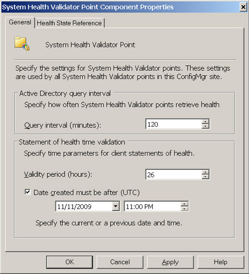
NAP SoH Time Validation
Although NAP SoH time validation can be set as wide as every 7 days, the default is every 26 hours, which could lead to poor user experience due to clients being restricted from the network after long weekends or holidays. Finding an acceptable threshold for your environment will require a balance between user acceptance and security risk mitigation. A good starting point is 4 or 5 days.
NAP’s success hinges on software update management (SUM). If SUM is not working correctly, clients can be accidently quarantined without the capability of remediation. Do not NAP-enforce software updates without approving and distributing those updates, because clients will otherwise be unable to remediate. An exception to this is for those highly critical patches, where the risk of infection is greater than network access by the non-compliant user or system.
ConfigMgr clients generate an SoH when the NAP agent requests it from the ConfigMgr client. The ConfigMgr client sends the SoH to the ConfigMgr SHV for verification. The SHV then sends a Statement of Health Response (SoHR) containing the client health state to the NPS. The NPS then sends the client heath state back to the client as an SoHR. The SoH always contains the following items:
• The client’s compliance status
• The client’s site
• A timestamp reference to identify the Configuration Manager NAP policies that the client used to evaluate its compliance
All NAP-capable clients generate an SoH with a compliant status, even when the site is not NAP enabled. Once NAP is enabled on the site, clients will evaluate their SoH against the NAP policies defined on the NPS.
Caution
Forcing Fresh Scans for NAP Evaluations
Perform thorough testing when using the Force a fresh scan for each evaluation option on the NAP agent within ConfigMgr. This feature will generate excessively long authentication times and may lead to an unfavorable boot-up/logon experience.
This is another setting to use with caution, but it may be of value in situations where a specific patch is required. Experiment with these enforcement settings in a lab environment, so the end user experience is clearly understood.
The SHV will accept a cached statement of health from clients if it is within the configured validity period and it does not conflict with the optional Date setting specified on the General tab of System Health Validator Point Component Properties. SoH messages may also contain failures when a client cannot determine its own health status. Figure 11.4 illustrates the System Health Validator Point Component configuration within the ConfigMgr console.
When clients generate an unknown response state failure, the NPS may not be able to auto-remediate the client. ConfigMgr clients may return a compliant SoH when they actually are noncompliant, and the SHV will send a noncompliant SoH to the NPS. This can occur when the client has not downloaded the new policies for compliance and is sending a cached SoH. When a client’s SoH is sent to the SHV/NPS with a noncompliant status and it is remediated, the client will generate another SoH and re-send it, with a list of the client’s MP, DP, and SUP, to the SHV, where it will be reevaluated and eventually granted access to the network.
Imaging is the process of deploying computer operating systems with the necessary settings and applications by overwriting the hard drive structure with a file that is a clone of another PC, usually referred to as the reference PC or master. Typically, companies have used one image for each hardware platform, and sometimes even one per department. This generally was because imaging technology was sector based, and swapping HAL (Hardware Abstraction Layer) types was not possible and not supported. The total cost of ownership (TCO) to image computer systems this way is very high, because it requires administrators to update numerous images (often dozens in large environments) as frequently as there are software changes, new patches, and so on. Image management therefore has been a full-time job in many enterprise environments.
In recent years, due to evolving hardware and software technology, imaging is again “sexy.” Administrators can create hardware-independent images, layering on dozens of applications, build those applications into the image, and perform maintenance on images in minutes. Previously, image deployments took between 30 minutes to 1 hour. Today, with ImageX (discussed in the “ImageX” section of the chapter), PCs are turned on, booted into WinPE, imaged, set up, and at the sign-on screen within several minutes. Sending users to go get a cup of coffee is now a viable window to perform a PC refresh for them!
In discussing imaging, a few key scenarios cover 99% of the imaging performed by system administrators. These are the New PC, Refresh, and Replace PC scenarios, which are covered in the following sections.
In the New PC scenario, there is no data backup. The system boots from PXE, CD/DVD, USB, or a locally installed bootable operating system such as WinPE. Once booted, the system then has the hard disk overwritten entirely with an image written to the drive. This scenario is sometimes referred to as “bare metal.”
Tip
New PC Scenario and Disk Wiping
It is a best practice to include a wipe of the disk and the MBR in the New PC scenario. This eliminates the hidden partitions most OEMs place on the hard drive and allows the administrator to reclaim that space for the OS. It is also common to implement this step if there is a need to image systems previously using a file format other than NTFS, such as Linux.
Several conditions may warrant the use of the New PC scenario:
• A PC is brand new, and it needs the corporate image put on it.
• The user of an existing system is no longer with the company, and the system needs reimaging for a new user.
• There is no concern with backing up the current user’s state or data of an existing system and it needs reimaging. This scenario could exist in a training room, lab, kiosk, and so on.
In the Refresh PC scenario, the PC has an existing user and it needs reimaging. This is sometimes called an in-place migration. The scenario requires backing up the user’s state using some automated process, such as the User State Migration Tool (USMT). The USMT allows the backup and storage of the user’s state to a network location or locally on a part of the hard drive. By default, OSD will use the state migration point (SMP) to store user state during an OS migration. The Refresh PC scenario can use the SMP, a folder on the hard drive, or a network share to store data from the OS the user was initially running. WinPE is copied to this same hard drive location, which the PC boots into and downloads the image into. It then applies the image to the disk, reboots again, and finally in the destination OS performs the necessary deployment tasks. In short, the Refresh PC scenario is the New PC scenario, but with a user state backup in front and no possibility of doing a disk wipe because of the minint folder.
Several conditions may call for the use of the Refresh PC scenario:
• The organization is upgrading from one version of Windows to another.
• The organization is deploying a new desktop due to implementing a large number of configuration changes or a standardization effort.
• The system is having problems, and the amount of time already spent troubleshooting makes reimaging cost effective.
The Replace PC scenario is the most complicated because it is similar to the Refresh PC scenario, but the user state backup occurs on the user’s old PC and the rest of the deployment occurs on the new PC. This may also be referred to as a side-by-side migration. The Replace PC scenario is used in the following situations:
• Replacing old hardware for newer hardware
• Hardware failure
Table 11.1 reflects the high-level phases of the three primary types of imaging scenarios. This does not reflect task sequences or all scenarios, but rather to clarifies how the scenarios differ.

Microsoft’s Windows imaging utility, ImageX.exe, is a file-based imaging technology that is hardware independent and highly compressed. ImageX, introduced in Windows Automated Installation Kit (WAIK) 0.9, allows for the capturing, maintenance, and deploying of Windows Imaging Format (WIM) images. Unlike sector-based imaging technologies, which make images of the 1’s and 0’s on the drive, ImageX copies all the files into its image, a WIM file. Because ImageX is file based, it has the ability to make only a copy of a file one time, no matter how many instances of that same file exist. This intelligence, along with file exclusion, allows WIM images to be substantially smaller than other sector-based imaging or cloning tools. It is not uncommon for ImageX WIM images to be one-third to one-half the size of other utilities’ images.
WIM images have the ability to hold multiple WIM images inside a single WIM image. For instance, the Windows Vista WIM has seven different versions or SKUs of Windows Vista in it. You can mount WIM images on an NTFS file system and customize them. This means there is no need to redo an image when most administrative types of changes need to occur. After you mount a WIM image, the following items can be modified within the image:
• Settings
• Modules
• Language packs
• Drivers
• Packages
• Files
Here’s the ImageX capture syntax:
imagex /config config.ini /capture [source] [image file] "IMAGEDESCRIPTION"
Here’s the ImageX append syntax:
imagex /append [source] [image file] "IMAGEDESCRIPTION"
Here’s the ImageX apply syntax:
imagex /apply [image file] [Destination Path] [Index]
And, finally, here’s the ImageX info syntax:
![]()
Here’s the process in which WIM images are edited offline:
Sector-based imaging has many issues that are time consuming and costly to work around. Sector-based technologies have a number of stipulations:
• The target for the image deployment must be the same HAL type as the reference PC.
• The same mass storage controller must be present on the target and reference PCs.
• The contents of the disk are destroyed in the process by writing over the destination disk Master File Table (MFT) and data, making it very difficult to handle many required migration tasks.
Although several sector-based imaging technologies allow you to edit an image after creating it, there are very few tasks that the administrator is capable of performing, and the file-deletion capability deletes the files without reclaiming the space. The significance of this last point means that a laptop image made from a reference PC with 4GB of RAM will most likely have a several GB page file and a 4GB hibernation file. That is approximately 6GB going into an image that is unnecessary, because it will be re-created on the first boot. The deletion of these files will not reclaim the space, but leaves the administrator with lots of room to add other items that usually are not needed in this volume. ImageX excels in this area, because it ignores the hibernation and page files during the capture phase.
Because sector-based imaging technologies image the disk at the “1’s and 0’s” level, a file such as winword.exe, which may be located on the system numerous times, is copied into the image as many times as it is present. ImageX, on the other hand, will only copy winword.exe once per version and place pointers for the other instances it finds. This single-instance file imaging allows for even greater efficiencies during the capture and apply phases, and produces smaller images in general. Because ImageX works at the file level, it provides the following capabilities:
• More flexibility and control over the deployed media.
• Rapid extraction of images to decrease setup time.
• A reduction in image size because of single instancing, which means the file data is stored separately from the path information. This enables files that exist in multiple paths or in multiple images to be stored once, and then shared across the images.
• Nondestructive application of images. ImageX does not perform an all-inclusive overwrite of the contents of your drive. You can selectively add and remove information.
• The ability to work across any platform supported by Windows.
• Two different compression algorithms, Fast and Maximum, to further reduce your image size.
• The ability to treat an image file like a directory. For example, you can add, copy, paste, and delete files using a file-management tool such as Windows Explorer.
ConfigMgr uses WinPE as its boot device for clients undergoing an OS deployment. The WinPE image is stored on the ConfigMgr server as a WIM file. It’s approximately 120MB in size and is named boot.wim. The ConfigMgr administrator provides these WIM files; they are not created by performing captures. In both the New PC and Replace PC scenarios, boot.wim is downloaded to the client PC from PXE, USB, or a CD/DVD. In the Refresh PC scenario, the client has boot.wim downloaded to the minint folder, and boot.ini is redirected to point at this location. This allows the reboot occurring after the user state capture to boot the system into WinPE, and for the OS deployment to commence the replacement.
ConfigMgr provides two default boot.wim images: one for x86 and one for x64. As with any other package, you must deploy these boot images to distribution points for clients to be able to download and use them. The boot.wim files that come with ConfigMgr will require customization to support the network drivers and storage controller drivers utilized throughout the deployments.
Tip
Customizing WinPE
ConfigMgr administrators have found it very useful to add a variety of tools to WinPE for troubleshooting deployments. Some of the tools found beneficial include SMS Trace32, Sysinternals tools, Microsoft’s Diagnostic and Recovery Toolkit (DART) tools, and other scripting tools. Anything you can use on a system to troubleshoot a failed deployment can be added to WinPE and made available on the client system this way. Keep in mind, though, that the more tools added, the larger the size of the boot.wim PE build.
Updating the boot images is a fairly simple process. Perform the following steps to update any boot image:
- Open the ConfigMgr console.
- Navigate to System Center Configuration Manager -> Site Database <Site Code> -> <Site Name> -> Computer Management -> Operating System Deployment -> Boot Images.
- Select the boot image desired, right-click, and select Properties.
- Select the Windows PE tab to add drivers.
- Select the Image tab to add/change an image property.
Another approach would include the following:
Alternatively, simply select the driver to add and drag it to the boot image under the Boot Images node.
ConfigMgr can maintain a driver catalog. This catalog keeps drivers external to the images and enables a centralized, easily administered location to store drivers. The driver catalog allows storing multiple versions of the same device driver to support systems that may still require older versions for support. The driver catalog is broken up into drivers and driver packages. A driver is an INF file, as well as several other files, that defines how an operating system is supposed to use a specific piece of hardware. The operating system matches the driver to the hardware by the Plug and Play ID (PnPID). The driver package is merely a grouping of drivers for a specific purpose that later can be deployed to distribution points.
As images are being built without drivers installed locally, the OS deployment process will have to provide the drivers to the target PC at the appropriate time. This occurs through the task sequencer by leveraging the WinPE Auto Apply Drivers task sequence step. This step automatically detects and installs all applicable Plug and Play device drivers it can locate in the driver catalog. For ConfigMgr to search in the driver catalog for the new device drivers, you should add the Auto Apply Drivers task sequence step to an existing task sequence. Auto Apply Drivers contains the following options:
• Name—A short user-defined name that describes the action taken in this step
• Description—More detailed information about the action taken in this step
• Install only the best matched compatible drivers—Specifies that the task sequence step will install only the best matched driver for each hardware device detected
• Install all compatible drivers—Specifies that the task sequence step will install all compatible drivers for each hardware device detected and allow Windows setup to choose the best driver
• Consider drivers from all categories—Specifies that the task sequence action will search all available driver categories for appropriate device drivers
• Limit driver matching to only consider drivers in selected categories—Specifies that the task sequence action will search for device drivers in specified driver categories for the appropriate device drivers
• Do unattended installation of unsigned drivers on versions of Windows where this is allowed—Allows this task sequence action to install unsigned Windows device drivers
Capturing an image is the first of three steps required to deploy an operating system. The second task is to create the task sequence, and the third task is the advertising of the task sequence to a collection. There are two possible methods for capturing an image:
• Build the reference PC and capture the image using capture media
• Create a task sequence to build and capture an operating system image
Many find the manual build method to be the easiest and least prone to errors from a capturing perspective, but it allows human error to occur on the build of the reference PC. Capturing a PC image using media requires the following steps:
-
Build the reference computer.
• Place the computer in a workgroup.
• The local Administrator password must be blank.
• Do not require password complexity in the local system policy.
- In the Configuration Manager console, navigate to System Center Configuration Manager -> Site Database <Site Code> -> <Site Name> -> Computer Management -> Operating System Deployment -> Task Sequences.
- On the Action menu, select Create Task Sequence Media Wizard. Select the Capture Media option and click Next.
- On the Media Type page, specify the type of media you want to use for the capture media.
- On the Media file line, enter the save path and filename of the media that will be used to perform the installation.
- Select the boot image that should be associated with the media.
- Create a bootable CD that contains the .ISO file you created by using an appropriate software application.
- Boot the computer into the full operating system and insert the capture CD.
- Run the Image Capture Wizard and identify the location for the captured image to be stored.
-
Add the captured image to Configuration Manager 2007 as an image package:
• Navigate to System Center Configuration Manager -> Site Database <Site Code> -> <Site Name> -> Computer Management -> Operating System Deployment -> Operating System Images.
• On the Action menu, or from the Actions pane, select Add Operating System Image to launch the Add Operating System Image Wizard. Complete the wizard to add the operating system image.
The other method of capturing an image is to create a task sequence to build and capture an operating system image. You can use a task sequence to build an operating system from scratch in an unattended format. This ensures consistency as the build is updated over time and removes the human error factor, because all tasks that occur to configure the OS are placed in the task sequencer as tasks. To create a new build-and-capture task sequence, perform the following steps:
- In the Configuration Manager console, navigate to System Center Configuration Manager -> Site Database <Site Code> -> <Site Name> -> Computer Management -> Operating System Deployment -> Task Sequences.
- Right-click the Task Sequences node and then click New/Task Sequence.
- On the Create a New Task Sequence page, select Build and capture a reference operating system image. Click Next.
- On the Task Sequence Information page, specify a name for the task sequence and add an optional comment. Specify the boot image that will be associated with the task sequence. Click Next.
- On the Install Windows Operating System page, specify the operating system install package to use for installing. Install the operating system by clicking the Browse button to launch the Select an Operating System Install Package dialog box and then selecting the operating system install package.
- On the Install the Windows Operating System page, specify the Windows product key and server license. By default, the local administrator account will be disabled. If you want to always use the same administrator account for the computers that will run this task sequence, select the Always use the same administrator password option and provide the password that will be used. Click Next.
- On the Configure the Network page, specify if the target computer will join a workgroup or a windows domain.
• If you are adding the target computer to a workgroup, you must type the name of the workgroup in the space provided.
• If you are adding the target computer to a Windows domain, click the Set button to launch the Windows User Account dialog box and specify the user account and password that are used to add the computer to the domain. The account you specify must have domain join permissions in the Windows domain or Organizational Unit (OU) to which you want to add the computer. You must also specify the name of the domain and OU to add the target computer. Click Next.
- On the Install ConfigMgr page, click the Browse button to launch the Select a Package dialog box. Then select the Configuration Manager 2007 package to use to install the Configuration Manager 2007 client. Specify the Configuration Manager 2007 client installation properties that will be used in the Installation properties window. Click Next.
- On the Include Updates in Image page, specify how the target computer will install assigned software updates by selecting the appropriate option.
- On the Install Software Packages page, click the New button to launch the Program Select dialog box. Click the Browse button to launch the Select a Package dialog box. Select the ConfigMgr packages you want to include and then click OK. Use the drop-down to select the associated programs to use.
- On the System Preparation page, specify the Configuration Manager 2007 package that contains the Sysprep tool. The Sysprep tool specified must support the operating system install package version selected in step 5.
- On the Image Properties page, specify identifying information that will be associated with the task sequence you are creating.
- On the Capture Image page, specify where the captured operating system image will be saved on the network. Click the Set button to launch the Windows User Account dialog box, and specify the network account to use to access the specified operating system image output location.
- To complete the creation of the new task sequence, on the Summary page, click Next.
- To confirm that the new task sequence was created using the properties specified, review the confirmation on the Confirmation page.
- Click Close to close the New Task Sequence Wizard.
Because ConfigMgr uses WinPE as the boot media to deploy an operating system, in theory you can use any type of image with the ConfigMgr deployment process. In addition, task sequences are the actual ConfigMgr objects advertised to a collection, which allows an infinite number of possibilities to be deployed to clients.
Windows Deployment Services (WDS), which is included with Microsoft WAIK and Windows Server 2003 SP 2, is the new version of Microsoft Remote Installation Services (RIS). WDS, similar to RIS, is used to deploy Windows operating systems to client PCs without requiring an administrator present. WDS uses a hook into DHCP to allow PXE booting of PCs, and it leverages the Trivial File Transfer Protocol (TFTP) to network boot clients into WinPE and apply images to them.
Windows Deployment Services provides the following benefits:
• Reduces the complexity of deployments. Also, the cost is built in to the licensing of Microsoft Windows Server.
• Empowers users to reimage their own PC.
• Allows network-based installation of Windows operating systems.
• Supports the New PC scenario.
• Supports mixed environments that include Windows XP/Vista and Microsoft Windows Server 2003/2008.
• Provides an end-to-end solution for the deployment of Windows operating systems to client computers and servers.
• Builds on standard Windows Server 2008 setup technologies, including WinPE, WIM files, and image-based setup.
When ConfigMgr 2007 shipped, it lacked a method of supporting the New PC scenario without IT administrators having to touch the ConfigMgr Administrator console for each PC they needed to image. ConfigMgr 2007 Release 2 (R2) resolved this issue. The issue was that an administrator could not image a PC using the New PC scenario without ConfigMgr first knowing about the PC. This meant that new PCs—either coming right from the OEM or without having had the ConfigMgr client on them—could not be imaged without a ConfigMgr admin going into the ConfigMgr console and creating the computer association.
Although PXE booting a PC and connecting to WDS works as expected, another issue arises when you introduce ConfigMgr into the equation. If the computer is unknown to the local ConfigMgr site, ConfigMgr will not respond to the PXE request. MDT offers a PXE filter, which hooks into WDS and ConfigMgr, allowing WDS to add PCs to the ConfigMgr database prior to ConfigMgr seeing the request.
Several other integration points exist between WDS/MDT and ConfigMgr. You can customize WinPE builds in the Deployment Workbench within MDT and then use them in ConfigMgr. You can use task sequences from the Workbench in ConfigMgr, but not without some modifications. Keep in mind the environment used for deployments in MDT does not exist in ConfigMgr, nor does a ConfigMgr client know about the MDT environment.
Intel Corporation, the world’s largest semiconductor company and inventor of the vast majority of computer processors in PCs today, has created a technology known as vPro. vPro is a set of features and logic built in to a PC motherboard, similar to how the MMX instruction set was built in Intel’s processors. Intel vPro is a combination of processor technologies, hardware enhancements, management features, and security technologies that allow remote access to the PC. This includes monitoring, maintenance, and management—all accomplished independently of the state of the operating system or power state of the PC. Intel vPro is intended to help businesses gain certain maintenance and servicing advantages, improve security, and reduce costs.
Intel systems that support vPro technology were originally branded with the logo depicted in Figure 11.5.

Since the vPro release, Intel has updated its processors and motherboards, also known as system boards, to include vPro technologies. The Core 2 Duo or Quad processors are the most recognizable new processors released by Intel. Since these new technologies have come out, Intel has released a new logo in 2008 for vPro, which is illustrated in Figure 11.6.

Intel has also created Active Management Technology, known as AMT. Intel AMT is a hardware-based technology for remotely managing and securing PCs that are “out of band.” Currently, Intel AMT is available in
• Desktop PCs with an Intel Core 2 processor with vPro technology
• Laptop PCs with a Centrino processor with vPro technology or a Centrino 2 processor with vPro technology
ConfigMgr 2007 with Service Pack 1 supports the AMT vPro clients, leveraging the integration between the Intel OOB Management console and the ConfigMgr console. Intel’s AMT and vPro technology make it possible for ConfigMgr to provision vPro clients without an OS deployed in scenarios where the client is down, the hard drive is corrupt, and so on—all while the PC is powered off.
Intel AMT is part of the Intel Management Engine, built in to PCs with Intel vPro technology. Intel AMT is built in to a secondary processor located on the motherboard. AMT is not intended for use by itself; it is intended for use with software management applications such as ConfigMgr. AMT performs hardware-based management over the TCP/IP protocol, which is unlike software-based management in ConfigMgr, because there is no dependency on the operating system. Examples of hardware-based management include DHCP (Dynamic Host Configuration Protocol), BOOTP (Bootstrap Protocol), and WOL (Wake On LAN).
Intel AMT includes hardware-based remote management features, security features, power-management features, and remote-configuration features. These features allow an IT technician to access an AMT PC when traditional techniques such as Remote Desktop or WOL are not available. Intel AMT operates on an independent hardware-based OOB communication channel, which operates regardless of whether the OS is running, functional, or even powered on. The hardware-based AMT features in laptop and desktop PCs include the following:
• Encrypted, remote communication channel between the IT console and Intel AMT.
• Ability for a wired PC outside the company’s firewall on an open local area network (LAN) to establish a secure communication tunnel (via AMT) back to the IT console. Examples of an open LAN include a wired laptop at home or at an SMB (small/medium business) site without a proxy server.
• Remote power up/power down/power cycle through encrypted WOL.
• Remote boot via integrated device electronics redirect (IDE-R).
• Console redirection, via serial over LAN (SOL).
• Hardware-based filters for monitoring packet headers in inbound and outbound network traffic for known threats and for monitoring known/unknown threats based on time-based heuristics. Laptops and desktop PCs have filters to monitor packet headers. Desktop PCs have packet-header filters and time-based filters.
• Isolation circuitry to port-block, rate-limit, or fully isolate a PC that might be compromised or infected.
• Agent presence checking, via hardware-based, policy-based programmable timers. A “miss” generates an event; you can specify that the event generate an alert.
• OOB alerting.
• Persistent event log, stored in protected AMT memory for software tools such as ConfigMgr to access while the OS is down.
• Access (preboot) the PC’s Universal Unique Identifier (UUID).
• Access (preboot) hardware asset information, such as a component’s manufacturer and model; this is updated every time the system goes through Power-On Self-Test (POST).
• Access (preboot) to a third-party data store (TPDS), a protected memory area that software vendors can use for version information, .DAT files, and other information.
• Remote configuration options, including certificate-based zero-touch remote configuration, USB key configuration (light-touch), and manual configuration.
Additional AMT features in laptop PCs include the following:
• Support for IEEE 802.11 a/g/n wireless protocols
• Cisco-compatible extensions for Voice over WLAN
Intel vPro platform features include the following:
• Support for IEEE 802.1x, Cisco Self Defending Network (SDN), and Microsoft Network Access Protection (NAP)
• Gigabit network connection or network wireless connection (on laptops)
• Intel Trusted Execution Technology (Intel TXT) and an industry-standard Trusted Platform Module (TPM), version 1.2
• Intel Virtualization Technology (Intel VT)
• 64-bit processors optimized for multitasking and multithreading
• 64-bit integrated graphics to provide enough performance that the PC does not need a discrete (separate) graphics card, even for graphics-intensive operating systems such as Microsoft Windows Vista
• Industry standards, such as ASF, XML, SOAP, TLS, HTTP authentication, Kerberos (Microsoft Active Directory), DASH (based on draft 1.0 specifications), and WS-MAN
• Quiet System Technology (QST), formerly called advanced fan speed control (AFSC)
• Architecture, package design, and technologies for power coordination and better thermals, in order to operate at very low voltages, use power more efficiently, and help meet Energy Star requirements
Because Intel AMT allows access to the PC below the OS level, security for the AMT features is a key concern. Security for communications between Intel AMT and the provisioning service and/or management console can be established in different ways, depending on the network environment. Security can be established via certificates and keys (TLS public key infrastructure, or TLS-PKI), pre-shared keys (TLS-PSK), or administrator password. Security technologies that protect access to the AMT features are built in to the hardware and firmware. As with other hardware-based features of AMT, the security technologies are active even if the PC is powered off, the OS has crashed, software agents are missing, or hardware (such as a hard drive or memory) has failed.
As you can tell from reading this chapter, the tools discussed will run independently from ConfigMgr. Also, ConfigMgr 2007 does not require these tools for its core functionality. Many of the tools and technologies mentioned are far more capable than can be covered in a single chapter. Several of the technologies are actually standalone technologies designed to address a specific need in the market for which Microsoft received feedback. Together, all these tools create a comprehensive solution and allow ConfigMgr to continue to be the best-of-breed solution for OS deployments, managing clients outside the firewall, enforcement of network access policies, and imaging in general.