
Adding Custom Hardware
In this chapter, you use everything you learned in previous chapters to begin using your Pi for small projects that combine electronic add-ons, Linux, Python, and a web server.
Connect a Digital Temperature Sensor
Create a Circuit on Stripboard
Understanding Electronics
To expand your Pi with add-on boards and components, you need a basic understanding of electronics. Professional electronic design is complex, but you can do a lot with a handful of components and a very basic understanding of what they do.
Understanding Volts and Amps

Electronic circuits work with two units called volts and amps. Volts (V) measure how much of a kick the electricity has. Small batteries produce a few volts. A household main supply produces hundreds of volts. Amps (A) measure the volume, or flow, of electricity. A car battery produces tens of amps. A small battery produces less than 1 amp. When you connect two circuits or components, one circuit must be able to produce the correct volts and amps to drive the other. If it does not, your design does not work. Volts are measured across a component. Amps are measured through it.
Understanding Decimal Notation

Circuit components and measurements are often labeled with abbreviated powers of 10. You should know the following: m (milli) is 1/1000, u or μ (micro) is 1 millionth, and n (nano) is 1 billionth. So 500mV is 0.5V. K or k (kilo) is thousand, and M is million. The abbreviation often replaces the decimal point, so 4k7 means 4700. Resistors use a special R multiplier, which means 1. 330R means 300 resistance units (called ohms — the official Ω symbol and the word are often left out).
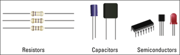
All electronic circuits use the same few kinds of components. Each component does something to the flow of electricity. A resistor partially blocks the flow, or the electronic equivalent of a pinched pipe. A capacitor acts like a tiny reservoir of electricity. A diode only allows electricity to pass in one direction. An LED (Light Emitting Diode) is a diode that can light up. A transistor works like a valve or switch. Relays are part-mechanical switches. You can use them to switch big and powerful circuits, such as heaters and cookers, from a small control source, like the Pi. Integrated Circuits (ICs) include many components, and are building blocks designed to perform a complex task.
Understanding Digital Logic

There are two kinds of electronic circuits. Analog circuits work with any value. Digital circuits work with two voltages. One represents 0/off/false, and a different voltage represents 1/on/true. Unfortunately, the voltages used are not standardized. Two popular options are 0V/3V, and 0V/5V on. The Pi works with 3V logic, but many popular relays and switches use 5V logic. You must include a buffer or level shifter circuit to make the two kinds of logic work together.
Understanding Breadboards
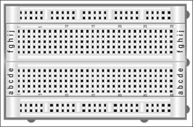
A breadboard is a plastic board with holes that cover internal metal tracks. You can use a breadboard to prototype, or plug together, a circuit without having to use a soldering iron. You plug the components directly between lines on the breadboard. You can use jumper cables to link the circuit to your Pi. Jumper cable ends are either male, with a pin you can plug into a breadboard, or female, with a socket you can place onto a GPIO, or General Purpose Input Output, pin. The most useful cables are male/female.
Understanding Pi Expansion Pins
The Pi includes a built-in connector with expansion pins, also known as GPIO (General Purpose Input Output) pins. The pins use 0V/3V logic, and you can set them up to read digital signals, to output digital signals, or some mix of both. The simplest way to control the pins with custom software is with a free Python module called RPi.GPIO, which is available online.
You can buy a component kit from a supplier such as Adafruit Industries (www.adafruit.com). Component kits include a breadboard and a selection of components with different values. They do not include a Pi board. You should also buy a digital multimeter so you can measure voltages and currents in your circuit. Basic models are available from $15 (£10). If you want to build a permanent circuit, you will need a soldering iron, and copper stripboard, which has component holes joined by strips of copper that can be soldered.
Using a Digital Multimeter
You can use a digital multimeter (DMM) to identify component values and check what is happening in a circuit. You can also check values visually by referring to an industry-standard color-code system, or by reading numbers and identification codes printed on each component and looking up its details online.
DMMs measure volts, amps, and ohms. Use a switch on the panel to select the measurement. Budget DMMs have manual ranging. You must guess an approximate range for the measurement using a switch on the panel. Expensive DMMs are autoranging and display the range automatically.
Using a Digital Multimeter
Note: This section assumes you have an introductory kit.
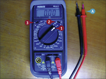
A Most DMMS have one black probe, and one red probe, plugged into one black socket and one red socket.
Note: If your DMM has a 10A socket, ignore it.
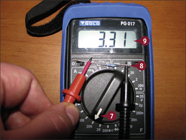
![]() To measure a small voltage, turn the switch so it points to the 20V setting.
To measure a small voltage, turn the switch so it points to the 20V setting.
Note: The setting may be 10V or 5V on some models.
![]() If there is a DC/AC switch, switch it to DC.
If there is a DC/AC switch, switch it to DC.
![]() Turn on the power.
Turn on the power.
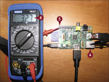
![]() Touch the black probe to any of the bare metal parts on the Pi board.
Touch the black probe to any of the bare metal parts on the Pi board.
![]() Touch the red probe to one of the pins at the top left of the board.
Touch the red probe to one of the pins at the top left of the board.
![]() Read the value.
Read the value.
Note: BE VERY CAREFUL not to connect two pins together by accident with a probe. You may reset your Pi or damage it.
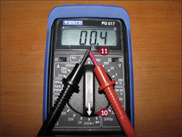
![]() To measure a resistor value, move the switch to one of the settings in the ohm (Ω) section.
To measure a resistor value, move the switch to one of the settings in the ohm (Ω) section.
Note: 20K is a good starting setting.
![]() Hold the probes in both hands across the resistor's leads.
Hold the probes in both hands across the resistor's leads.
![]() Read the value. To work out the tens multiplier, assume the value is a fraction of the range setting.
Read the value. To work out the tens multiplier, assume the value is a fraction of the range setting.
Note: If the value is too big for the range, the display shows OL or INF. Select a bigger range. If the display shows 0.00, select a smaller range. Try again.
![]() If your meter has a small speaker symbol, you can use it to test continuity, or connections. Select the continuity range.
If your meter has a small speaker symbol, you can use it to test continuity, or connections. Select the continuity range.
![]() Touch the tips of the probes together.
Touch the tips of the probes together.
The meter makes a buzzing sound as long as there is a connection between the pins.
Note: You can use this feature to check if there is a break in a wire or cable, by checking if there is a connection between the ends of the wire.
Note: Not all meters have this feature.
Set Up GPIO Control Software
You can use a free Python module called RPi.GPIO to control the GPIO pins from Python. RPi.GPIO is an unofficial user-led project and is not preinstalled on the Pi. You cannot install it with apt-get install. You must download it from a web site, and install it manually.
Installation from the command line is easy as long as you know the “magic word” commands. One minor complication is that the software is updated regularly. To find the latest version, visit the project website and make a note of the version number. Use that number in your commands.
Set Up GPIO Control Software
![]() Launch the desktop and open the Midori web browser.
Launch the desktop and open the Midori web browser.
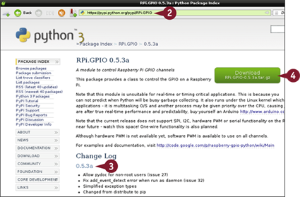
![]() Type https://pypi.python.org/pypi/RPi.GPIO in the address bar.
Type https://pypi.python.org/pypi/RPi.GPIO in the address bar.
![]() Make a note of the current version number.
Make a note of the current version number.
![]() Click Download.
Click Download.
The Open or Download File dialog box appears.
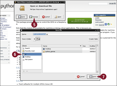
![]() Click Save As.
Click Save As.
The Save File dialog box appears.
![]() Select your home (Pi) directory.
Select your home (Pi) directory.
![]() Click Save.
Click Save.
Midori downloads and saves the file.
Note: If Midori does not work, open LX Terminal, type wget http://pypi.python.org/packages/source/R/RPi.GPIO/RPi.GPIO-[versionnumber].tar.gz, and press ![]() .
.
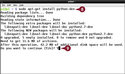
![]() In LX Terminal, type sudo apt-get install python-dev and press
In LX Terminal, type sudo apt-get install python-dev and press ![]() .
.
![]() Type Y and press
Type Y and press ![]() at the prompt.
at the prompt.
Linux downloads and installs the Python development tools.
Note: You must install these tools before you can build and install the RPi.GPIO module.
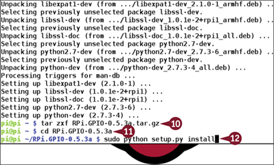
![]() Type tar zxf [the name of the downloaded file] and press
Type tar zxf [the name of the downloaded file] and press ![]() .
.
Note: tar is the Linux equivalent of the Windows/Mac Unzip tool. It decompresses a compressed file into a directory.
![]() Type cd [the name of the downloaded file] and press
Type cd [the name of the downloaded file] and press ![]() .
.
![]() Type sudo python setup.py install and press
Type sudo python setup.py install and press ![]() .
.
Linux builds and installs the RPi.GPIO module. You can now use it in your Python projects.
Control an LED with a Button
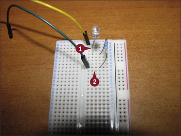
You can breadboard a simple circuit around the Pi to control an LED with a button or switch. Both components connect to the Pi's GPIO (general-purpose input output) pins. To light an LED, connect a GPIO pin to the LED, to a small resistor (220R to 470R) next, and finally to GND.
To use a switch, connect one end directly to GND. Connect the other end to a GPIO pin. You must add a pull-up resistor that “pulls” the pin to 3V3 — that is, logic one, when it is not connected to anything. Use a medium (4k7 to 10k) resistor.
Control an LED with a Button
Note: You can find the code used in this section on this book's website, www.wiley.com/go/tyvraspberrypi.
Note: These steps assume you have a breadboard with power lines on at least one side, and a collection of male-to-female jumper leads.
Note: On a breadboard, the holes are joined horizontally, except for the power lines on either or both sides, which are joined vertically.
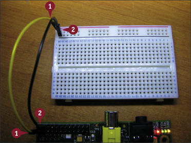
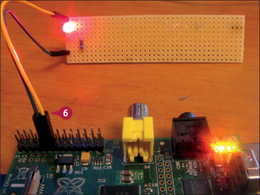
![]() Connect pin 1 (3V3) — the lower pin at the far left — to one power line.
Connect pin 1 (3V3) — the lower pin at the far left — to one power line.
![]() Connect pin 6 (GND) — the third pin from the left on the top row — to another line.
Connect pin 6 (GND) — the third pin from the left on the top row — to another line.
Note: Use the diagram at www.modmypi.com/blog/raspberry-pi-gpio-cheat-sheet as a reference.
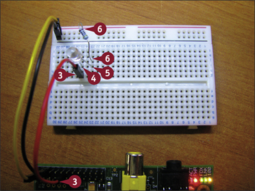
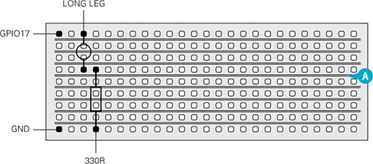
![]() Connect pin 11 to a line on the breadboard.
Connect pin 11 to a line on the breadboard.
![]() Plug the long leg of the LED into the same line.
Plug the long leg of the LED into the same line.
![]() Plug the short leg of the LED into a lower line.
Plug the short leg of the LED into a lower line.
![]() Join that line to the GND power line through a 330R resistor.
Join that line to the GND power line through a 330R resistor.
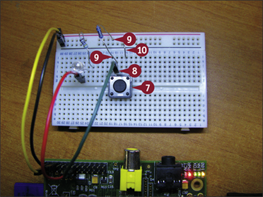
![]() Place the switch into the breadboard so that the two switch connectors are over the break in the board.
Place the switch into the breadboard so that the two switch connectors are over the break in the board.
![]() Connect pin 13 to the top of the switch.
Connect pin 13 to the top of the switch.
![]() Connect pin 13 to the 3V3 power line via a 4k7 resistor.
Connect pin 13 to the 3V3 power line via a 4k7 resistor.
Note: You can use any resistor from 4k7 to 10k.
![]() Connect the other end of the switch directly to 0V.
Connect the other end of the switch directly to 0V.
Note: Use a male-to-male jumper lead. If you do not have one, cut the leg off a resistor and use that.
![]() Launch the desktop and IDLE.
Launch the desktop and IDLE.
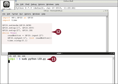
![]() Type the code shown, and save it to a file called LED.py.
Type the code shown, and save it to a file called LED.py.
![]() Open LXTerminal, type sudo python LED.py, and press
Open LXTerminal, type sudo python LED.py, and press ![]() .
.
The LED lights when you push the switch.
Note: You must run the code as root with sudo. You cannot run it from IDLE.
Note: Press ![]() , type C exit(), and press
, type C exit(), and press ![]() to quit Python.
to quit Python.
Connect a Digital Temperature Sensor
You can use the Dallas D18B20 temperature sensor to measure temperatures with your Pi. Be sure to buy the D18B20, not the D18S20. You can buy the sensors as components on Amazon and eBay. You can also buy premade waterproof sensors.
The sensor is small, but sophisticated, and includes a simple microprocessor. It connects to the Pi's GPIO pins using a 1-wire bus. You can install simple free software on your Pi to set it up and read values. The readings appear as a file in a directory with a name that includes your sensor's unique serial number.
Connect a Digital Temperature Sensor

![]() Plug a sensor across three breadboard lines, with the flat surface toward you.
Plug a sensor across three breadboard lines, with the flat surface toward you.
Note: If you connect the sensor the wrong way, it does not work.
![]() Use a jumper cable to connect the left pin on the sensor to the GND GPIO pin — the third pin from the left on the top row.
Use a jumper cable to connect the left pin on the sensor to the GND GPIO pin — the third pin from the left on the top row.
Note: Use the diagram at www.modmypi.com/blog/raspberry-pi-gpio-cheat-sheet as a reference for the GPIO pin layout.
![]() Use a jumper cable to connect the right pin on the sensor to the 3V3 GPIO pin — the first pin from the left on the bottom row.
Use a jumper cable to connect the right pin on the sensor to the 3V3 GPIO pin — the first pin from the left on the bottom row.
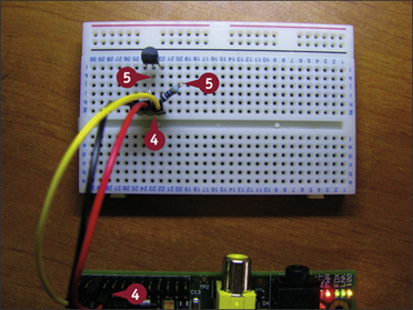
![]() Use a jumper cable to connect the middle pin on the sensor to the GPIO 4 pin — the fourth pin from the left on the lower row.
Use a jumper cable to connect the middle pin on the sensor to the GPIO 4 pin — the fourth pin from the left on the lower row.
![]() Plug a 4k7 resistor between the middle and right sensor pins.
Plug a 4k7 resistor between the middle and right sensor pins.
Note: Bend one leg to fit it into the small space. Be careful to keep the two legs separate.
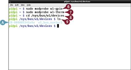
![]() In LXTerminal or at the command line, type sudo modprobe w1-gpio and press
In LXTerminal or at the command line, type sudo modprobe w1-gpio and press ![]() .
.
![]() Type sudo modprobe w1-therm and press
Type sudo modprobe w1-therm and press ![]() .
.
Note: Steps 6 and 7 load driver software for the sensor.
![]() Type cd /sys/bus/w1/devices and press
Type cd /sys/bus/w1/devices and press ![]() .
.
![]() Type ls and press
Type ls and press ![]() .
.
A You should see a directory named 28-xxxxxxxxxxxx, where the x's represent a unique serial number.
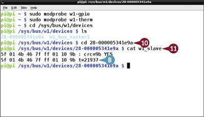
![]() Type cd followed by the directory name and press
Type cd followed by the directory name and press ![]() .
.
![]() Type cat w1_slave and press
Type cat w1_slave and press ![]() .
.
BThe driver displays the temperature data after t=. Divide by 1000 to get degrees Centigrade.
Log Sensor Readings to a File
You can use Python and crontab to log sensor readings to a file. This example uses the temperature sensor from the previous section. It logs readings to a file in the /var/www directory so they can be displayed by your Pi's web server, as discussed in the next section.
Because the sensors sometime return errors, this code checks if a reading is valid and rereads the sensor if it is not. If a sensor is permanently damaged, this code may get stuck in a loop and stop working. As an exercise, add code that stops checking after ten failures and writes an error message to the file.
Log Sensor Readings to a File
![]() At the command prompt or in LXTerminal, type nano .bashrc and press
At the command prompt or in LXTerminal, type nano .bashrc and press ![]() .
.
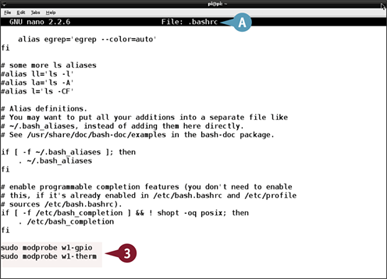
A Linux opens the .bashrc file.
![]() Scroll to the end of the file.
Scroll to the end of the file.
![]() Type sudo modprobe w1-gpio and press
Type sudo modprobe w1-gpio and press ![]() . Type sudo modprobe w1-therm and press
. Type sudo modprobe w1-therm and press ![]() .
.
![]() Press
Press ![]() +
+![]() , and press
, and press ![]() , and press
, and press ![]() +
+![]() to save the file and quit.
to save the file and quit.
Note: Making this edit tells your Pi to load the 1-wire driver for the sensor automatically when you log in.
![]() Launch the desktop with startx if it is not already open, and double-click IDLE to launch it.
Launch the desktop with startx if it is not already open, and double-click IDLE to launch it.
![]() Click File.
Click File.
![]() Click New Window.
Click New Window.
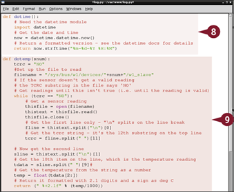
![]() Add code as shown for a function that reads the time and returns a formatted date/time string.
Add code as shown for a function that reads the time and returns a formatted date/time string.
![]() Add code as shown to create a function that reads a temperature from the probe.
Add code as shown to create a function that reads a temperature from the probe.
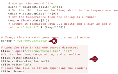
![]() Add code that defines the unique ID for your sensor.
Add code that defines the unique ID for your sensor.
Note: Use the ID from the previous section, “Connect a Digital Temperature Sensor.”
![]() Add code that appends the current time and date created by the first function, and the temperature from the second function to a file called temps.txt.
Add code that appends the current time and date created by the first function, and the temperature from the second function to a file called temps.txt.
![]() Save the file to /var/www instead of your home directory.
Save the file to /var/www instead of your home directory.
![]() Open LXTerminal.
Open LXTerminal.
![]() Type crontab -e and press
Type crontab -e and press ![]() .
.
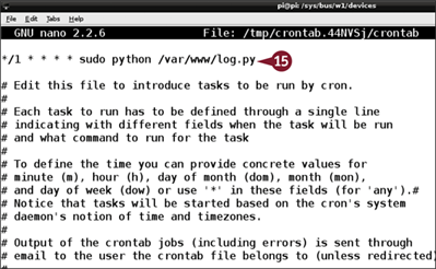
![]() Type */1 * * * * sudo python /var/www/log.py on the first line.
Type */1 * * * * sudo python /var/www/log.py on the first line.
![]() Press
Press ![]() +
+![]() , press
, press ![]() , and press
, and press ![]() +
+![]() to save and quit.
to save and quit.
Your Pi appends a new temperature reading to the file once a minute.
Note: You can view the log with sudo cat /var/www/temps.txt.
Note: You can find the code used in this section on this book's website, www.wiley.com/go/tyvraspberrypi.
Graph Readings on a Web Page
You can use a free software tool called GNUPLOT to read a file of sensor readings and convert them into a graph. You can then embed the graph, and perhaps the sensor readings, into a web page, so you can view a set of readings from a web browser. GNUPLOT has many options, but you can ignore most of them and get good results with the default settings.
To use GNUPLOT, install it with apt-get install, and create a PLT file with your settings. This example includes PHP web server code to graph the most recent 300 readings whenever a page is loaded.
Graph Readings on a Web Page
Note: You can find the code used in this section on this book's website, www.wiley.com/go/tyvraspberrypi.

![]() At the command line or LXTerminal, type sudo apt-get install gnuplot and press
At the command line or LXTerminal, type sudo apt-get install gnuplot and press ![]() .
.
![]() Type Y and press
Type Y and press ![]() to confirm installation at the prompt.
to confirm installation at the prompt.
Note: Some online tutorials mention gnuplot-x11. This is a different package. You cannot use it with the code in this section.
![]() Type sudo nano /var/www/index.php and press
Type sudo nano /var/www/index.php and press ![]() .
.
![]() Type <?php and press
Type <?php and press ![]() to start a block of PHP code.
to start a block of PHP code.
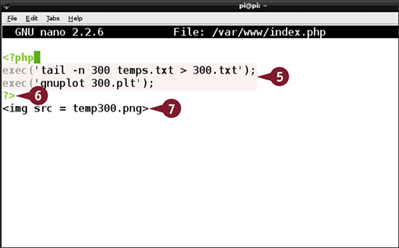
![]() Add a line to copy the last 300 entries in temps.txt to a file called 300.txt, and another to run GNUPLOT, taking settings from a file called 300.plt.
Add a line to copy the last 300 entries in temps.txt to a file called 300.txt, and another to run GNUPLOT, taking settings from a file called 300.plt.
![]() Type ?> and press
Type ?> and press ![]() to finish the PHP code.
to finish the PHP code.
Note: PHP's exec runs a one-line Linux command string.
![]() Add a line of HTML to display an image called 300.png.
Add a line of HTML to display an image called 300.png.
![]() Press
Press ![]() +
+![]() , press
, press ![]() , and press
, and press ![]() +
+![]() to save and quit.
to save and quit.
![]() Type sudo nano /var/www/300.plt and press
Type sudo nano /var/www/300.plt and press ![]() to create a settings file for GNUPLOT.
to create a settings file for GNUPLOT.
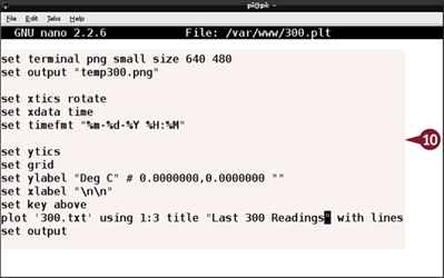
![]() Add the code shown.
Add the code shown.
Note: You can find out more about these “magic word” commands on the GNUPLOT documentation page at www.gnuplot.info/documentation.html.
![]() Double-click the Midori browser to open it.
Double-click the Midori browser to open it.

![]() Delete any existing contents in the address bar.
Delete any existing contents in the address bar.
![]() Type http://127.0.0.1 in the address bar and press
Type http://127.0.0.1 in the address bar and press ![]() .
.
A The Pi displays a graph of the last 300 temperature readings.
Note: If your temps.txt file has fewer than 300 readings, the graph shows all the readings logged so far.
Connect a Real-Time Clock
You can connect a real-time clock card to your Pi. The Pi keeps good time while it is powered up and can access the Internet. However, if the power goes off and it cannot access the Internet when it reboots, its “fake hardware clock” time will be wrong.
This project uses a simple add-on clock board supplied by Hobbytronics (www.hobbytronics.co.uk) with the popular DS1302 clock chip. You can find similar boards from other suppliers of Pi add-ons. See the section “Understanding Further Options” for a list.
Connect a Real-Time Clock
Note: You can find the code used in this section on this book's website, www.wiley.com/go/tyvraspberrypi.
Note: This section uses a breadboard to link sets of male/female jumpers. If you use female-to-female jumpers, you do not need the breadboard.
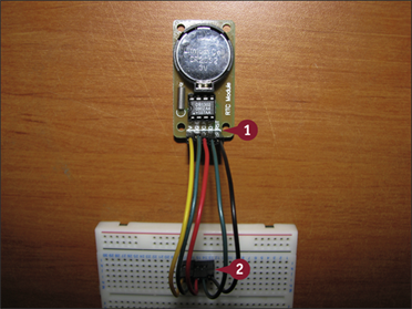
![]() Plug five jumpers onto the pins of the clock board.
Plug five jumpers onto the pins of the clock board.
![]() Plug the jumpers into rows on the breadboard.
Plug the jumpers into rows on the breadboard.
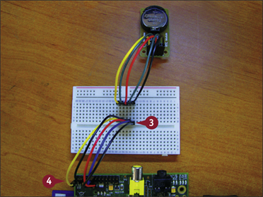
![]() Plug another row of jumpers into the same lines.
Plug another row of jumpers into the same lines.
![]() Plug the jumpers into the GPIO pins on the Pi as follows, counting from the top: 3V3, GND, GPIO 27, GPIO 18, GPIO 17.
Plug the jumpers into the GPIO pins on the Pi as follows, counting from the top: 3V3, GND, GPIO 27, GPIO 18, GPIO 17.
Note: These instructions assume you have a version 2 Pi board. For a version 1 board, use the instructions and software at www.hobbytronics.co.uk/tutorials-code/raspberry-pi-tutorials/raspberry-pi-real-time-clock.
![]() Use Midori or wget to download the code for a software driver from this book's website to a directory named rtc.
Use Midori or wget to download the code for a software driver from this book's website to a directory named rtc.
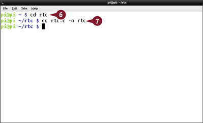
![]() Type cd rtc and press
Type cd rtc and press ![]() if you are not already in rtc.
if you are not already in rtc.
![]() Type cc rtc.c - o rtc and press
Type cc rtc.c - o rtc and press ![]() to create a binary.
to create a binary.
The source code builds a binary you can run from the command line.
Note: The source code is written in the C language. You can read it with cat, or edit it with nano.
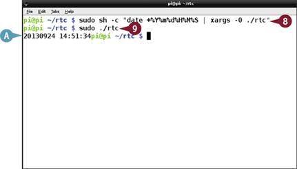
![]() Type sudo sh -c "date +%Y%m%d%H%M%S | xargs -0 ./rtc" and press
Type sudo sh -c "date +%Y%m%d%H%M%S | xargs -0 ./rtc" and press ![]() .
.
Note: This complex “magic word” command pipes a formatted date string to the clock driver as root to set the clock.
![]() Type sudo ./rtc and press
Type sudo ./rtc and press ![]() .
.
A The clock driver displays the time.
Create a Python Webcam
You can connect a standard USB webcam to your Pi and use it as a camera. Most recent USB cams are compatible with the Pi, although very cheap or very old cams may not be. If you have a webcam you can experiment with it to see if it works.
The Pi does not include webcam software. You can use the camera features in Pygame to create a simple still webcam, embedding a Python/Pygame script in a web page, and adding one line of HTML to make it refresh automatically.
Create a Python Webcam
Note: You can find the code used in this section on this book's website, www.wiley.com/go/tyvraspberrypi.
![]() Connect a webcam to your Pi's USB hub and reboot.
Connect a webcam to your Pi's USB hub and reboot.
![]() Launch the desktop and IDLE.
Launch the desktop and IDLE.
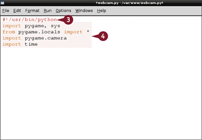
![]() Type #!/usr/bin/python and press
Type #!/usr/bin/python and press ![]() .
.
Note: Add this line to the start of a file when you want to create a Python script.
![]() Add code to import pygame, sys, the pygame camera module, and the Python time module.
Add code to import pygame, sys, the pygame camera module, and the Python time module.
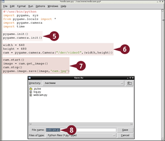
![]() Add code to initialize Pygame and the Pygame camera module.
Add code to initialize Pygame and the Pygame camera module.
![]() Add code to set the width and height of the image and to load the image from /dev/video0.
Add code to set the width and height of the image and to load the image from /dev/video0.
![]() Add code to open the camera, capture an image, close the camera, and save the image to a file.
Add code to open the camera, capture an image, close the camera, and save the image to a file.
![]() Save the file as webcam.py to /var/www.
Save the file as webcam.py to /var/www.
Note: If you get an error, save the file to your home directory and use File Manager in root mode to copy it to /var/www.
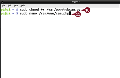
![]() Type sudo chmod +x /var/www/webcam.py and press
Type sudo chmod +x /var/www/webcam.py and press ![]() .
.
Note: Step 10 makes it possible for the web server to run the webcam script.
![]() Type sudo nano /var/www/cam.php and press
Type sudo nano /var/www/cam.php and press ![]() to create a new PHP file.
to create a new PHP file.
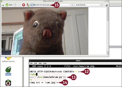
![]() Type <META HTTP.EQUIV=Refresh CONTENT="3"> and press
Type <META HTTP.EQUIV=Refresh CONTENT="3"> and press ![]() .
.
Note: This line makes a webpage reload itself every 3 seconds.
![]() Add code to run the webcam script using PHP's exec command.
Add code to run the webcam script using PHP's exec command.
![]() Add a line to load and display the image created by the script.
Add a line to load and display the image created by the script.
![]() Press
Press ![]() +
+![]() , press
, press ![]() , and press
, and press ![]() +
+![]() to save and quit.
to save and quit.
![]() Open Midori at http://127.0.0.1/cam.php.
Open Midori at http://127.0.0.1/cam.php.
Note: On a networked computer, use [your Pi's static address]/cam.php.
The camera captures and displays stills every 3 seconds.
Control a Relay
You can connect a relay to your Pi to switch power circuits. A relay is a logic-controlled switch. This example uses two relays controlled with 5V logic.
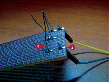
Because the Pi uses 3V logic you must use a level-converter board. The board in this example (supplied by Hobbytronics) has four lines with A (5V) and B (3V) connections. Each line works in either direction. The board is through-hole plated, which means there is metal through and around the holes on both sides. The holes work with jumper lead pins if you apply some side pressure to force a connection.
Control a Relay
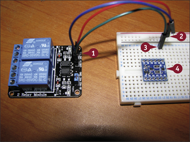
![]() Connect jumpers to the Vcc and the GND and a switch control pin on the relay board.
Connect jumpers to the Vcc and the GND and a switch control pin on the relay board.
![]() Plug the Vcc (5V) jumper into one of the breadboard power lines.
Plug the Vcc (5V) jumper into one of the breadboard power lines.
![]() Plug the GND jumper into a track on the breadboard.
Plug the GND jumper into a track on the breadboard.
![]() Place the level-converter board on the breadboard so the 0V hole lines up with GND.
Place the level-converter board on the breadboard so the 0V hole lines up with GND.
Note: Use the diagram at www.modmypi.com/blog/raspberry-pi-gpio-cheat-sheet for steps 5 to 9.
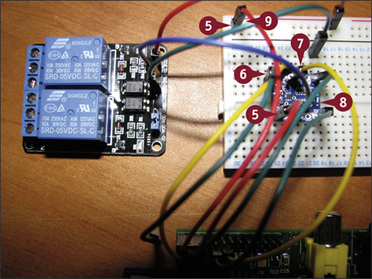
![]() Connect your Pi's 5V power GPIO pins to the level converter and the power line.
Connect your Pi's 5V power GPIO pins to the level converter and the power line.
![]() Connect your Pi's 3V3 power GPIO pin to the level converter.
Connect your Pi's 3V3 power GPIO pin to the level converter.
![]() Connect GPIO pin 17 to one of the 3V3 B-side holes.
Connect GPIO pin 17 to one of the 3V3 B-side holes.
![]() Connect the relay control from step 1 to the corresponding 5V A-side hole.
Connect the relay control from step 1 to the corresponding 5V A-side hole.
![]() Insert a single jumper pin at the top or bottom of the converter board to force the holes to connect with the push pins inside them.
Insert a single jumper pin at the top or bottom of the converter board to force the holes to connect with the push pins inside them.
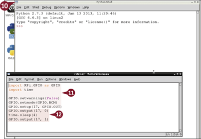
![]() Boot your Pi, type startx, and press
Boot your Pi, type startx, and press ![]() to launch the desktop, and then launch IDLE.
to launch the desktop, and then launch IDLE.
![]() Add code to load the GPIO and time modules, and set GPIO pin 17 as an output.
Add code to load the GPIO and time modules, and set GPIO pin 17 as an output.
![]() Add code to turn on GPIO 17, wait 4 seconds, and turn it off.
Add code to turn on GPIO 17, wait 4 seconds, and turn it off.
Note: If you use a different relay and/or converter, you may need to turn on your relay with logic 1 and turn it off with logic 0.
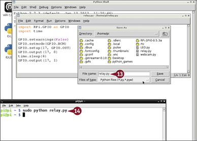
![]() Save the file as relay.py.
Save the file as relay.py.
![]() In LXTerminal or at the command line, type sudo python relay.py and press
In LXTerminal or at the command line, type sudo python relay.py and press ![]() .
.
Your Pi switches the relay on, waits 4 seconds, and switches it off. The relay clicks when it switches. An LED indicates its state.
Note: You may need to repeat step 14 a couple of times until the circuit settles.
Note: You can now connect 12V lighting or some other circuit to the screw terminals on the relay. Modify the Python code as necessary.
Learn to Solder
You can create long-lasting custom hardware by soldering components together. Many intermediate to advanced Pi kits require some soldering. You typically solder components to copper stripboard, which is described in the next section, “Create a Circuit on Stripboard,” or to a premade circuit board.
Light your work area with a bright light, use a fine-tipped 15W or 25W soldering iron — available for $15 (£10) from electronics stores — and wait until the bit is hot before starting. Heat the joint for long enough to allow the solder to flow, and keep the joint still while the solder cools and sets.
Learn to Solder
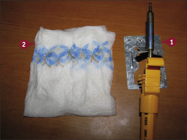
![]() Find or improvise a fireproof, melt-proof stand for the iron. Most kits include a basic stand.
Find or improvise a fireproof, melt-proof stand for the iron. Most kits include a basic stand.
![]() If your kit does not include a sponge, find or improvise a wiper for the tip.
If your kit does not include a sponge, find or improvise a wiper for the tip.
Note: You can use a wet pad of paper towels or toilet paper. Do not use a domestic dish scourer because the plastic will melt and damage your iron.
![]() Plug in your soldering iron and wait for the tip to heat up.
Plug in your soldering iron and wait for the tip to heat up.
Note: This can take a few minutes.
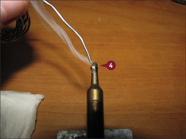
![]() Hold a line of solder against the tip.
Hold a line of solder against the tip.
When the iron is ready to use, the solder melts instantly. If the iron is too cool, the solder does not melt.
Note: The first time you use an iron, “tin the bit” by melting solder on it, leaving it for a while, and wiping it clean. This conditions the bit and prolongs its life.
Note: Apply enough solder to cover the bit, but not so much that it splashes down the iron.
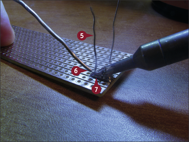
![]() To solder a component to a board, insert the component leads through the correct holes so they stick out on the side with the copper strips or circuit traces.
To solder a component to a board, insert the component leads through the correct holes so they stick out on the side with the copper strips or circuit traces.
![]() Place the solder next to the component lead.
Place the solder next to the component lead.
![]() Apply the tip of the iron so it melts the solder and heats the pad and the component lead.
Apply the tip of the iron so it melts the solder and heats the pad and the component lead.
![]() Wait until the solder melts, pause for a second, and remove the iron.
Wait until the solder melts, pause for a second, and remove the iron.
Note: This example uses too much solder to make the process clear. Use as little solder as possible to make a strong joint.
![]() Do not disturb the joint for a few seconds while the joint cools.
Do not disturb the joint for a few seconds while the joint cools.
Note: The component remains hot for 10 seconds or more. Do not touch it.
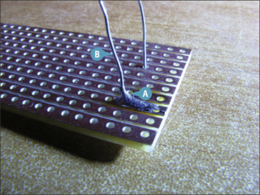
A A successful joint looks like a tiny hill. The joint should be solid. The component should not move.
B If the remaining lead is too long, snip it to size with snips or the cutting edge on a pair of pliers.
Create a Circuit on Stripboard
You can use stripboard for small custom electronic circuits. Stripboard is a thin plastic laminate board with a grid of holes joined by lines of copper strips. To use stripboard, insert component leads and pins into the holes and solder them to the strips. You often need to cut some of the strips to avoid a short circuit.
If you breadboard a circuit, you can use the breadboard component layout as a starting point for a stripboard layout. Creating a working stripboard layout requires a combination of care, attention to detail, common sense, and occasionally some trial and error.
Create a Circuit on Stripboard
Note: This very simple example uses the LED circuit from the section “Control an LED with a Button.”
![]() Look at the layout. Note the power lines, position of the circuit components jumpers, and whether the circuit needs to use the break in the middle of the breadboard.
Look at the layout. Note the power lines, position of the circuit components jumpers, and whether the circuit needs to use the break in the middle of the breadboard.
Note: You can make the layout clearer by rotating the breadboard so that the strips are horizontal to match the horizontal lines on the stripboard.
Note: You can find free guides online. The number of holes and strips may not match your board. You can also use graph paper or even lined paper. Step A is optional but highly recommended.
A You can print out a stripboard guide and sketch the size and position of the components. Bend component leads and preplace the components to discover how many holes they cover.
![]() Solder all the components to the stripboard.
Solder all the components to the stripboard.
Note: Start with the items that protrude the least from the top of the board. You can hold them in place with the weight of the board by turning it upside down, or with electrical tape, or with Blu-Tack.
Note: Use as little solder as possible so as not to join adjacent strips.
![]() Cut the leads off the longer components.
Cut the leads off the longer components.
![]() Cut any tracks if you need to.
Cut any tracks if you need to.
![]() Connect and test your circuit.
Connect and test your circuit.
The circuit should work correctly.
Note: If the circuit does not work, check for blobs of solder across strips, strips that should be cut but are not, components in the wrong places, components the wrong way around, or errors in the layout.
Note: A good first check is to make sure that power and other connections are correct. Use a digital multimeter (DMM) to test if the board is receiving the correct voltages.
Understanding Further Options
You can use the skills you learned in this book to tackle more complex projects. Some possibilities include more complex sensors, video and audio expansion, a more powerful web server, and robotics. The Pi is only one example of a much wider world of single-board computers you can build into bigger projects.
Understanding Add-Ons
You can add various extras to your Pi, including small display panels with optional touch sensing, larger display screens, simple limited number/letter LCDs (liquid crystal displays), keypads and switch arrays, LED displays, various sensors, motors, and better audio among others.
Using Add-Ons

Although every add-on is different, most follow the same steps you learn in this book. You explore the options, connect them to the Pi's GPIO pins, install or build suitable software, often using someone else's “magic word” commands, and then customize the add-ons with your own code. You do not usually need advanced electronic design skills. But you do need to know basic Python and Linux.
Understanding Expansion Boards
You can connect individual components to your Pi by breadboarding them or soldering them onto stripboard. For convenience, you can also buy various pre-made expansion boards. Some boards include general features, such as a prototyping area, which is like a piece of stripboard that clips onto the Pi. Others add very specific extras, such as digital input and output pins, analog connectors that can measure or generate a varying voltage, breakout boards that make your Pi's pins more accessible with clear labels, and buffers, which protect your Pi's connections from damage.
Understanding Arduino
The Arduino product range is a natural complement to the Pi. The range was designed as an affordable way to build systems around a computer chip that is even simpler and slower than the chip in the Pi. Arduino boards are available in a range of size, price, and performance options. You can extend the boards by plugging in shields, or expansion boards that slot on top of an Arduino to add a specific feature. Arduino boards have more electronic connection options than the Pi, and are supported by a wider range of free software and online tutorials. You can link a Pi and an Arduino together to get the best of both worlds.
Understanding C

The C language used with the Arduino is also available for free on the Pi. A full introduction to C is beyond the scope of an introductory book. In outline, you create software by writing code with an editor and passing it through a compiler tool called cc. You typically build various sections of code separately, and link them together — also with cc — to create a finished binary. Because some projects have many files, you can use a tool called make, or an alternative called cmake, to manage the building and linking process.

Adafruit Industries (www.adafruit.com) is one of the biggest suppliers of add-ons. Although based in the United States, you can find a list of international resellers on the website. Sparkfun (www.sparkfun.com) offers a wider range of components and options for constructors with some electronic design experience. In the United Kingdom, Ciseco (www.ciseco.co.uk), SK Pang (www.skpang.co.uk), and Cool Components (www.coolcomponents.co.uk) offer add-ons for the Pi and for other single-board computers.