Chapter Six. Orthographic Projection
Objectives
After studying the material in this chapter, you should be able to:
1. Recognize and sketch the symbol for third-angle projection.
2. List the six principal views of projection.
3. Sketch the top, front, and right-side views of an object with normal, inclined, and oblique surfaces.
4. Understand which views show depth in a drawing that shows top, front, and right-side views.
5. Know the meaning of normal, inclined, and oblique surfaces.
6. Compare using a 2D CAD program with sketching on a sheet of paper.
7. List the dimensions that transfer between top, front, and right-side views.
8. Transfer depth between the top and right-side views.
9. Label points where surfaces intersect.
10. Select a good arrangement of generated 2D drawing views to place from a 3D model.
Refer to the following standard:
• ANSI/ASME Y14.3 Multiview and Sectional View Drawings

Understanding Projections
To make and interpret drawings, you need to understand projections and the standard arrangement of views. You also need to be familiar with the geometry of solid objects and be able to visualize a 3D object that is represented in a 2D sketch or drawing. The ability to identify whether surfaces are normal, inclined, or oblique in orientation can help you visualize. Common features such as vertices, edges, contours, fillets, holes, and rounds are shown in a standard way, which makes drawings simpler to create and help prevent them from being misinterpreted.
Views of Objects
A photograph shows an object as it appears to the observer but not necessarily as it is. It cannot describe the object accurately, no matter what distance or which direction it is taken from, because it does not show the exact shapes and sizes of the parts. It would be impossible to create an accurate 3D model of an object using only a photograph for reference because it shows only one view. It is a 2D representation of a 3D object.
Drawings are 2D representations as well, but unlike photos, they allow you to record sizes and shapes precisely. In engineering and other fields, a complete and clear description of the shape and size of an object is necessary to be sure that it is manufactured exactly as the designer intended. To provide this information about a 3D object, typically a number of systematically arranged views are used.
The system of views is called multiview projection. Each view provides certain definite information. For example, a front view shows the true shape and size of surfaces that are parallel to the front of the object. An example of a 3D object and its front view projection is shown in Figure 6.1. Figure 6.2 shows the same part and the six principal viewing directions. Figure 6.3 shows the same six views of a house.

The Six Standard Views
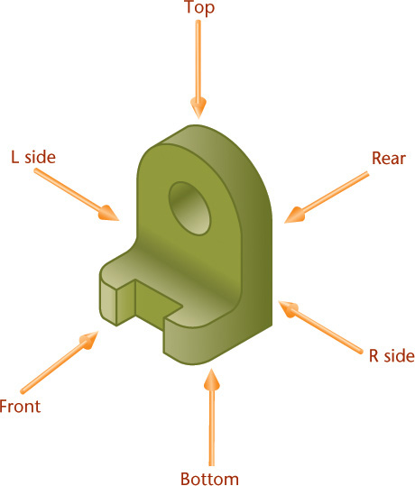
Any object can be viewed from six mutually perpendicular directions, as shown in Figure 6.2. These are called the six principal views.
You can think of the six views as what an observer would see by moving around the object. As shown in Figure 6.3, the observer can walk around a house and view its front, sides, and rear. You can imagine the top view as seen by an observer from an airplane and the bottom, or worm’s-eye view, as seen from underneath. The term plan may also be used for the top view. The term elevation is used for all views showing the height of the building. These terms are regularly used in architectural drawing and occasionally in other fields.
To make drawings easier to read, the views are arranged on the paper in a standard way. The views in Figure 6.3 show the American National Standard arrangement. The top, front, and bottom views align vertically. The rear, left-side, front, and right-side views align horizontally. To draw a view out of place is a serious error and is generally regarded as one of the worst mistakes in drawing. See Figure 6.4 for an illustration of how to visualize the different views.

6.4 Revolving the Object to Produce Views. You can experience different views by revolving an object, as shown. (a) First, hold the object in the front view position. (b) To get the top view, tilt the object toward you to bring the top of the object into your view. (c) To get the right-side view, begin with the object’s front view facing you and revolve it to bring the right side toward you. To see views of the rear, bottom, or left side, you would simply turn the object to bring those sides toward you.
Principal Dimensions
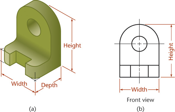
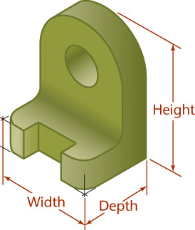
The three principal dimensions of an object are width, height, and depth (Figure 6.5). In technical drawing, these fixed terms are used for dimensions shown in certain views, regardless of the shape of the object. The terms length and thickness are not used because they may be misleading.
The front view shows only the height and width of the object and not the depth. In fact, any principal view of a 3D object shows only two of the three principal dimensions; the third is found in an adjacent view. Height is shown in the rear, left-side, front, and right-side views. Width is shown in the rear, top, front, and bottom views. Depth is shown in the left-side, top, right-side, and bottom views.
Projection Method
Figure 6.6 illustrates the front view of an object drawn using an orthographic projection. Imagine a sheet of glass parallel to the front surfaces of the object. This represents the plane of projection. The outline on the plane of projection shows how the object appears to the observer. In orthographic projection, rays (or projectors) from all points on the edges or contours of the object extend parallel to each other and perpendicular to the plane of projection. The word orthographic means “at right angles.”

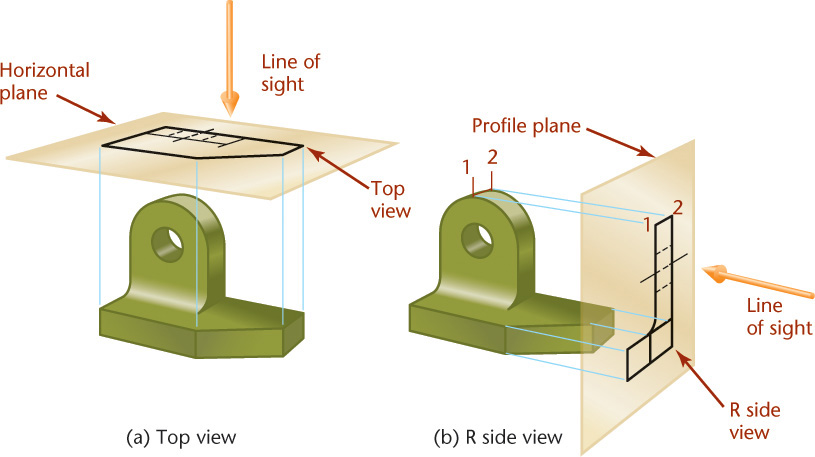
Examples of top and side views are shown in Figure 6.7. Specific names are given to the planes of projection. The front view is projected to the frontal plane. The top view is projected to the horizontal plane. The side view is projected to the profile plane.
The Glass Box
One way to understand the standard arrangement of views on the sheet of paper is to envision a glass box. If planes of projection were placed parallel to each principal face of the object, they would form a box, as shown in Figure 6.8. The outside observer would see six standard views (front, rear, top, bottom, right side, left side) of the object through the sides of this imaginary glass box.

To organize the views of a 3D object on a flat sheet of paper, imagine the six planes of the glass box being unfolded to lie flat, as shown in Figure 6.9. Think of all planes except the rear plane as hinged to the frontal plane. The rear plane is usually hinged to the left-side plane. Each plane folds out away from the frontal plane. The representation of the hinge lines of the glass box in a drawing are known as folding lines. The positions of these six planes after they have been unfolded are shown in Figure 6.10.


Carefully identify each of these planes and corresponding views with the planes’ original position in the glass box.
In Figure 6.10, lines extend around the glass box from one view to another on the planes of projection. These are the projectors from a point in one view to the same point in another view. The size and position of the object in the glass box does not change. This explains why the top view is the same width as the front view and why it is placed directly above the front view. The same relation exists between the front and bottom views. Therefore, the front, top, and bottom views all line up vertically and are the same width. The rear, left-side, front, and right-side views all line up horizontally and are the same height.
Objects do not change position in the box, so the top view must be the same distance from the folding line O/Z as the right-side view is from the folding line O/Y. The bottom and left-side views are the same distance from their respective folding lines as are the right-side and the top views. The top, right-side, bottom, and left-side views are all the same distance from the respective folding lines and show the same depth.
The front, top, and right-side views of the object shown in the previous figures are shown in Figure 6.11a, but instead of a glass box, folding lines are shown between the views. These folding lines correspond to the hinge lines of the glass box.

The H/F folding line, between the top and front views, is the intersection of the horizontal and frontal planes. The F/P folding line, between the front and side views, is the intersection of the frontal and profile planes.
Although you should understand folding lines, particularly because they are useful in solving problems in descriptive geometry, they are usually left off the drawing, as in Figure 6.11b. Instead of using the folding lines as reference lines for marking depth measurements in the top and side views, you may use the front surface (A) of the object as a reference line. Note that D1, D2, and all other depth measurements correspond in the two views as if folding lines were used.
Spacing between Views
Spacing between views is mainly a matter of appearance. Views should be spaced well apart but close enough to appear related to each other. You may need to leave space between the views to add dimensions.
Transferring Depth Dimensions
The depth dimensions in the top and side views must correspond point-for-point. When using 2D CAD or instruments, transfer these distances accurately.
You can transfer dimensions between the top and side views either with dividers or with a scale, as shown in Figures 6.12a and 6.12b. Marking the distances on a scrap of paper and using it like a scale to transfer the distance to the other view is another method that works well when sketching.

You may find it convenient to use a 45° miter line to project dimensions between top and side views, as shown in Figure 6.12c. Because the miter line is drawn at 45°, depths shown vertically in the top view can be transferred to be shown as horizontal depths in the side view and vice versa.
Measuring from a Reference Surface
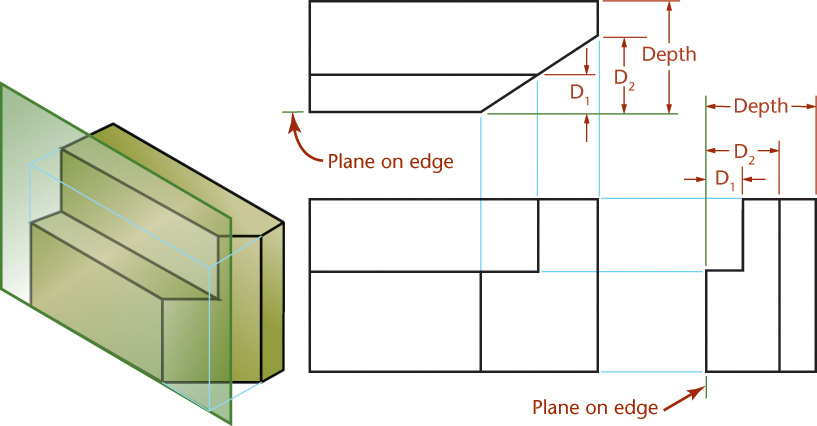
To transfer a dimension from one view to a related view (a view that shares that dimension), measure from a plane that shows on edge in both views as in Figure 6.13.
Necessary Views
Figure 6.14 shows that right- and left-side views are essentially mirror images of each other, only with different lines appearing hidden. Hidden lines use a dashed-line pattern to represent portions of the object that are not directly visible from that direction of sight. Both the right and left views do not need to be shown, so usually the right-side view is drawn. This is also true of the top and bottom views, and of the front and rear views. The top, front, and right-side views, arranged together, are shown in Figure 6.15. These are called the three regular views because they are the views most frequently used.
A sketch or drawing should contain only the views needed to clearly and completely describe the object. These minimally required views are referred to as the necessary views. Choose the views that have the fewest hidden lines and show essential contours or shapes most clearly. Complicated objects may require more than three views or special views such as partial views.
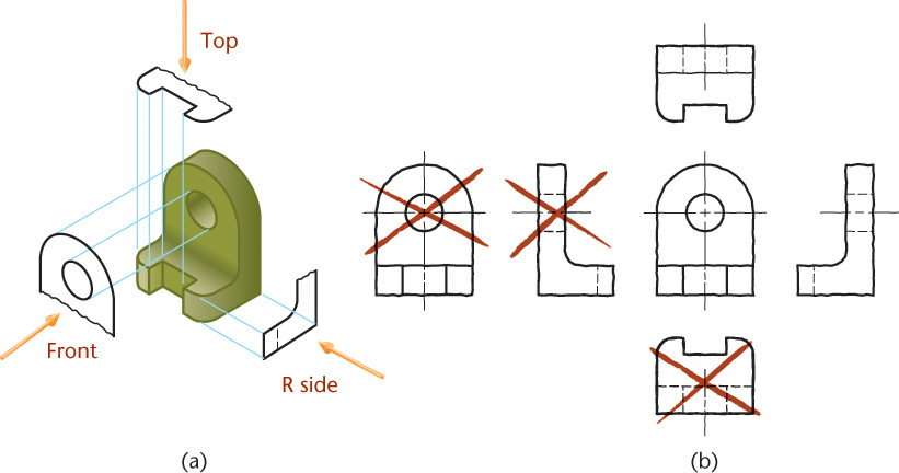
Many objects need only two views to clearly describe their shape. If an object requires only two views, and the left-side and right-side views show the object equally well, use the right-side view. If an object requires only two views, and the top and bottom views show the object equally well, choose the top view. If only two views are necessary and the top view and right-side view show the object equally well, choose the combination that fits best on your paper. Some examples are shown in Figure 6.16.

Often, a single view supplemented by a note or by lettered symbols is enough, as shown in Figure 6.17. Objects that can be shown using a single view usually have a uniform thickness. This connecting rod is an exception. It is possible to show it in a single view owing to the way it is dimensioned.

Orientation of the Front View
Four views of a compact automobile are shown in Figure 6.18. The view chosen for the front view in this case is the side, not the front, of the automobile.

• The front view should show a large surface of the part parallel to the front viewing plane.
• The front view should show the shape of the object clearly.
• The front view should show the object in a usual, stable, or operating position, particularly for familiar objects.
• When possible, a machine part is drawn in the orientation it occupies in the assembly.
• Usually, screws, bolts, shafts, tubes, and other elongated parts are drawn in a horizontal position, as shown in Figure 6.19.

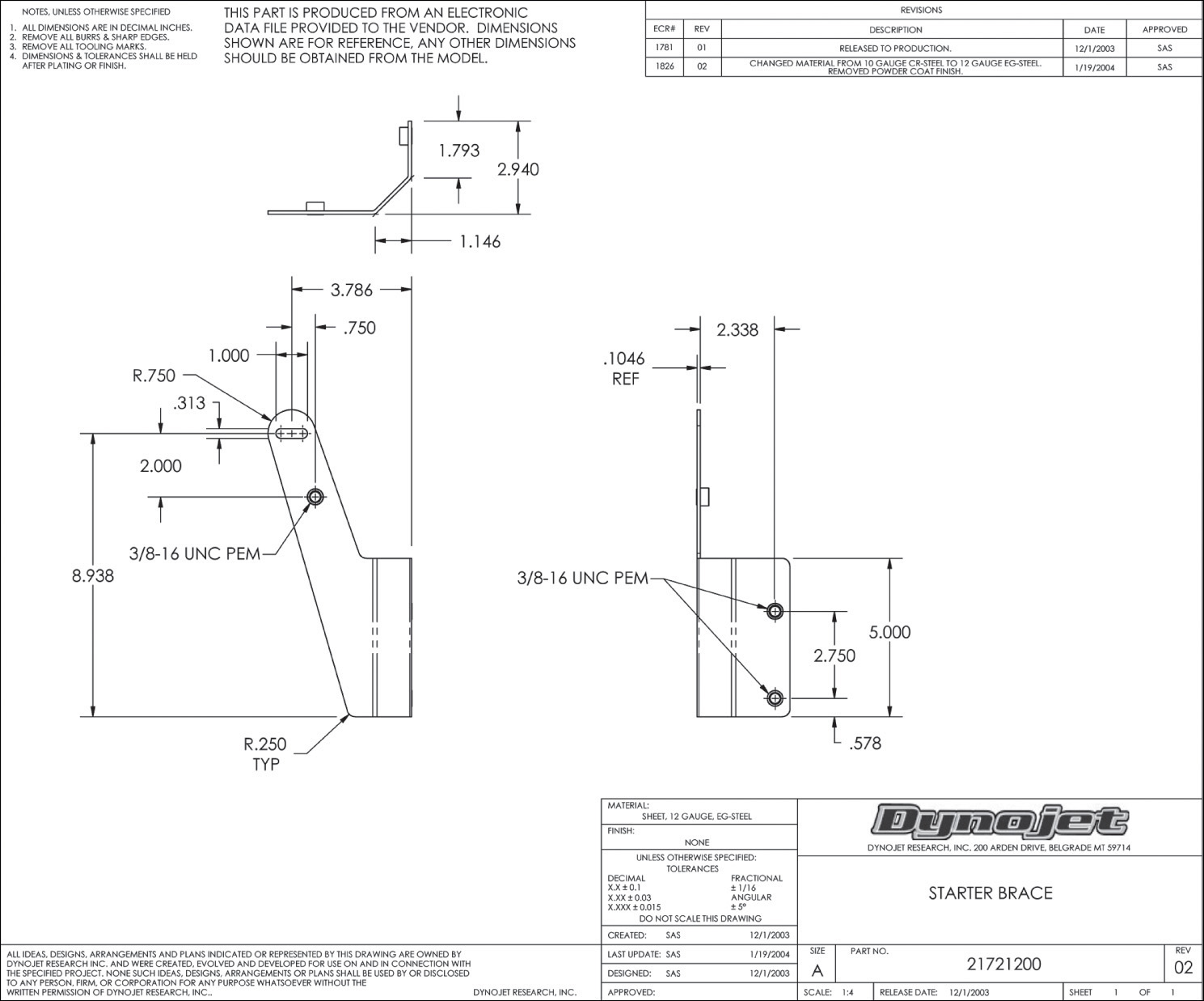
6.19 A long part looks best oriented with the long axis horizontal on the sheet. (Courtesy of Dynojet Research, Inc.)
CAD software can be used to generate orthographic views directly from a 3D model, as shown in Figure 6.20. The pictorial view of this model is shown in Figure 6.21. When using CAD you still need to select a good orientation so that the part shows clearly in the front view. The standard arrangement of views shown in Figure 6.15 should be used. Do not be tempted to rearrange the views of your CAD drawing to fit the sheet better, unless you are using removed views.

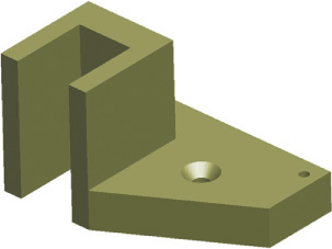
6.21 Pictorial View of the CAD Model Shown in Figure 6.20 (Courtesy of Dynojet Research, Inc.)
First- and Third-Angle Projection
As you saw earlier in this chapter, you can imagine projecting views as unfolding a glass box made from the viewing planes. There are two main systems used for projecting and unfolding the views: third-angle projection, which is used in the United States, Canada, and some other countries, and first-angle projection, which is used primarily in Europe and Asia. Difficulty in interpreting the drawing and manufacturing errors can result when a first-angle drawing is confused with a third-angle drawing.
Because of the global nature of technical drawings, you should thoroughly understand both methods. However, since it can be confusing to try to learn both methods intermixed, this text presents third-angle projection throughout. When you are comfortable with creating third-angle projection drawings, revisit this section. You will see that the two drawing methods are very similar, and you should be able to extend the same skills to either type of drawing.
Third-Angle Projection
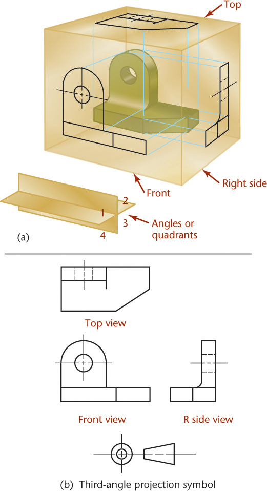
Figure 6.22a shows the concept of third-angle orthographic projection. To avoid misunderstanding, international projection symbols have been developed to distinguish between first-angle and third-angle projections on drawings. The symbol in Figure 6.22b shows two views of a truncated cone. You can examine the arrangement of the views in the symbol to determine whether first- or third-angle projection was used. On international drawings you should be sure to include this symbol.
To understand the two systems, think of the vertical and horizontal planes of projection, shown in Figure 6.22a, as indefinite in extent and intersecting at 90° with each other; the four angles produced are called the first, second, third, and fourth angles (similar to naming quadrants on a graph.) If the object to be drawn is placed below the horizontal plane and behind the vertical plane, as in the glass box you saw earlier, the object is said to be in the third angle. In third-angle projection, the views are produced as if the observer is outside, looking in.
Alternative Arrangements for Third-Angle Projection
Sometimes, drawing three views using the conventional arrangement wastes space. (For example, see the wide, flat object in Figure 6.23a.) Using the space on the paper efficiently may prevent the need to use a reduced scale.

For these cases, there is another acceptable arrangement of third-angle projection views. Imagine unfolding the glass box as shown in Figure 6.23b. The views are arranged differently, with the right-side view aligned with the top view. These views are still using third-angle projection.
In this case, the profile (side view) is hinged to the horizontal plane (top view) instead of to the frontal plane (front view) so that the side view is beside the top view when unfolded (Figure 6.23b). Notice that the side view is rotated 90° from the orientation shown in the side view in Figure 6.23a in this placement. Now you can directly project the depth dimension from the top view into the side view.
If necessary, you may place the side view horizontally across from the bottom view (so the profile plane is hinged to the bottom plane of the projection).
Similarly, the rear view may be placed directly above the top view or under the bottom view. In this case, the rear plane is considered hinged to the horizontal or bottom plane and rotated to coincide with the frontal plane.
First-Angle Projection
If the object is placed above the horizontal plane and in front of the vertical plane, the object is in the first angle. In first-angle projection the observer looks through the object to the planes of projection. The right-side view is still obtained by looking toward the right side of the object, the front by looking toward the front, and the top by looking down toward the top; but the views are projected from the object onto a plane behind the object in each case.
The biggest difference between third-angle projection and first-angle projection is how the planes of the glass box are unfolded, as shown in Figure 6.24. In first-angle projection, the right-side view is to the left of the front view, and the top view is below the front view, as shown.
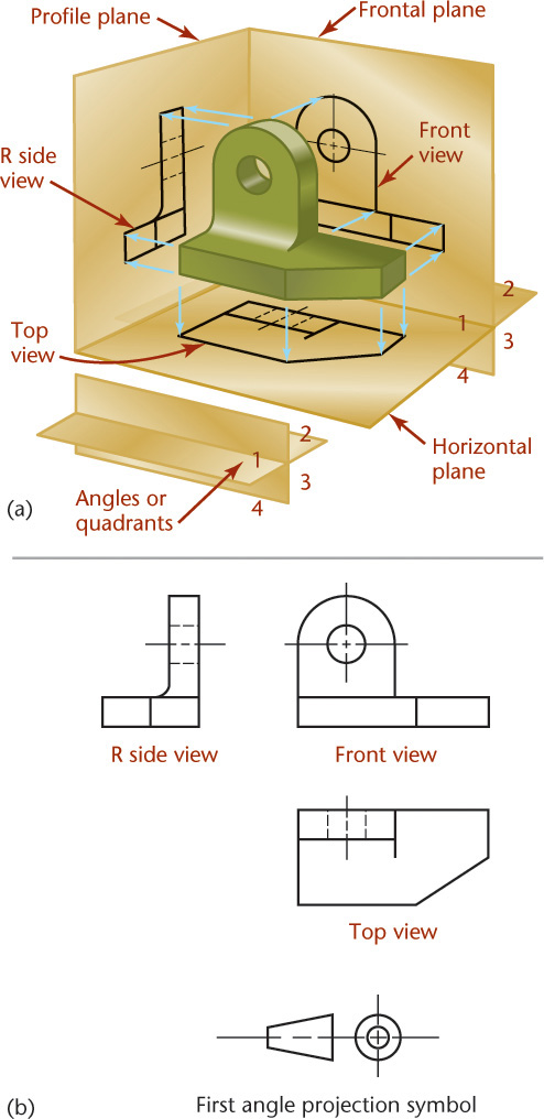
6.24 First-Angle Projection. An object that is above the horizontal plane and in front of the vertical plane is in the first angle. An observer looks through the object to the planes of projection.
You should understand the difference between the two systems and know the symbol that is placed on drawings to indicate which has been used. Keep in mind that you will use third-angle projection throughout this book.
Projection System Drawing Symbol
The symbol shown in Figure 6.25 is used on drawings to indicate which system of projection is used. Whenever drawings will be used internationally you should include this symbol in the title block area.

Hidden Lines
One advantage of orthographic views over photographs is that each view can show the entire object from that viewing direction. A photograph shows only the visible surface of an object, but an orthographic view shows the object all the way through, as if it were transparent.
Thick, dark lines represent features of the object that are directly visible. Dashed lines represent features that would be hidden behind other surfaces.
Figure 6.26 shows a part that has internal features. When a 3D view of this model is rendered using a transparent material, as shown in Figure 6.27, you can see the internal features. Figure 6.28 shows this part from the front as it would be oriented in an orthographic drawing. The features that are hidden from view are shown in orthographic views using the hidden line pattern as shown in Figure 6.29.
Whenever possible, choose views that show features with visible lines. Use hidden lines where they are needed to make the drawing clear.
Some practices for representing intersections of hidden lines with other lines may be difficult to follow when using CAD. In CAD, adjust the line patterns so that the hidden lines in your drawing have the best appearance possible.
• show the axis of symmetry for a feature or part
• indicate a path of motion
• show the location for bolt-hole circles and other circular patterns
The centerline pattern is composed of three dashes: one long dash on each end with a short dash in the middle. In the drawing, centerlines are shown thin and black. Because a centerline is not an actual part of the object, it extends beyond the symmetrical feature as shown in Figure 6.30.

The most common shape that needs a centerline is a cylindrical hole. Figure 6.31 shows centerlines in a drawing. In the circular view of a hole, the centerline should form a cross to mark the center location. When a feature is too small for the centerline pattern to be shown with the long-short-long dash pattern, it is acceptable to use a straight line. You will learn more about showing hidden lines and centerlines in the technique sections.

6.1 Hidden Line Technique
You can save time and reduce clutter by leaving out hidden lines that aren’t necessary as long as you are certain that the remaining lines describe the object clearly and completely. If you omit unnecessary hidden lines, add a note to let the reader know that the lines were left out intentionally and that it is not an error in the drawing.
Sketch hidden lines by eye, using thin dark dashes about 5 mm long and spaced about 1 mm apart. Hidden lines should be as dark as other lines in the drawing, but should be thin.
When hidden lines intersect each other in the drawing, their dashes should meet. In general, hidden lines should intersect neatly with visible lines at the edge of an object. Leave a gap when a hidden line aligns with a visible line, so that the visible line’s length remains clear.
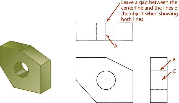
6.2 Precedence of Lines
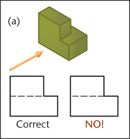
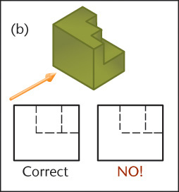
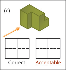
Visible lines, hidden lines, and centerlines often coincide on a drawing. There are rules for deciding which line to show. A visible line always takes precedence over and covers up a centerline or a hidden line when they coincide in a view, as shown at A and B in Figure 6.32. A hidden line takes precedence over a centerline, as shown at C. At A the ends of the centerline are shown separated from the view by short gaps, but the centerline is usually left off entirely. Figure 6.33 shows examples of correct and incorrect hidden lines.
Correct and Incorrect Practices for Hidden Lines
Make a hidden line join a visible line, except when it causes the visible line to extend too far, as shown here.
Leave a gap whenever a hidden line is a continuation of a visible line.
Make hidden lines intersect at L and T corners.
Make a hidden line “jump” a visible line when possible.
Draw parallel hidden lines so that the dashes are staggered, as in bricklaying.

When two or three hidden lines meet at a point, join the dashes, as shown for the bottom of this drilled hole.

The same rule of joining the dashes when two or three hidden lines meet at a point applies for the top of this countersunk hole.

Hidden lines should not join visible lines when this makes the visible line extend too far
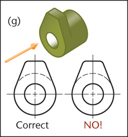
Draw hidden arcs with the arc joining the centerline, as in upper example. There should not be a gap between the arc and the centerline, as in the lower example with the straightaway joining the centerline.
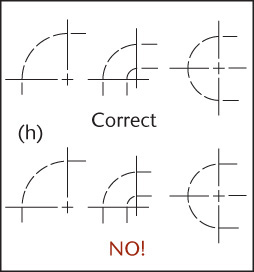
6.33 Correct and Incorrect Practices for Hidden Lines
Tip
When sketching, accent the beginning and end of each dash by pressing down on the pencil. Make hidden lines as tidy as you can so they are easy to interpret. Be sure to make hidden line dashes longer than gaps so they clearly represent lines. Your CAD system may have limitations that make it impractical to comply with these requirements. If so, strive for hidden lines that are clear and easy to interpret.
6.3 Centerlines
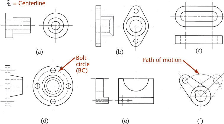
Centerlines (symbol: ![]() ) are used to indicate symmetrical axes of objects or features, bolt circles, and paths of motion as shown in Figure 6.34. Center-lines are useful in dimensioning. They are not needed on unimportant rounded or filleted corners or on other shapes that are self-locating.
) are used to indicate symmetrical axes of objects or features, bolt circles, and paths of motion as shown in Figure 6.34. Center-lines are useful in dimensioning. They are not needed on unimportant rounded or filleted corners or on other shapes that are self-locating.
6.4 Laying Out a Drawing
If you use 2D CAD, you can move the views later, keeping them in alignment, so you do not need to give as much attention to placement of the views in the beginning as if you were laying them out by hand. When using 3D CAD to generate views, you should still plan how the sheet will show the information clearly and select the necessary views to best represent the shape of the part. Although you can easily change the scale of a CAD drawing after it is created, placing the dimensions and views on the sheet requires some planning. If you consider the purpose of the drawing, the planned scale, and the space that will be required for adding notes and dimensions, you will save the time of having to rearrange their placement later.
Step by Step: Hand Layout of a Metric Three-View Drawing
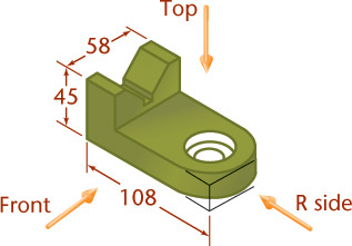
![]() Determine space desired between the front and right-side views (C), say 32 mm. Add this space to the sum of the length of the views that will be aligned along the long edge of the sheet (108 + 58 + 32 = 198). To set equal distances to the paper edge, subtract this total from the sheet width, then divide the remaining number by two (280 –198 = 82, and 82 ÷ 2 = 41). Do the same for the views to be aligned along the short side of the paper, selecting a desired space between the views. Space D need not match C. Remember to leave space for dimensions as you plan your sheet.
Determine space desired between the front and right-side views (C), say 32 mm. Add this space to the sum of the length of the views that will be aligned along the long edge of the sheet (108 + 58 + 32 = 198). To set equal distances to the paper edge, subtract this total from the sheet width, then divide the remaining number by two (280 –198 = 82, and 82 ÷ 2 = 41). Do the same for the views to be aligned along the short side of the paper, selecting a desired space between the views. Space D need not match C. Remember to leave space for dimensions as you plan your sheet.

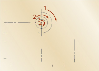
![]() Set off vertical and horizontal spacing measurements with light tick marks along the edge of the sheet as shown. Locate centerlines from these spacing marks, and construct arcs and circles.
Set off vertical and horizontal spacing measurements with light tick marks along the edge of the sheet as shown. Locate centerlines from these spacing marks, and construct arcs and circles.
![]() Construct the views, drawing horizontal, vertical, and then inclined construction lines in the order shown above.
Construct the views, drawing horizontal, vertical, and then inclined construction lines in the order shown above.

![]() Add hidden lines and darken final lines.
Add hidden lines and darken final lines.
6.5 Developing Views from 3D Models
For most 3D software, creating orthographic views from the model is simple. Two basic steps are required: selecting a location on the page where the orthographic view will be placed and selecting the viewing direction. Adding more orthographic views is even easier, as they may be automatically placed in relation to the initial view.
Even if your CAD package does not automate the creation of orthographic drawing views to this extent, creating orthographic views directly from the 3D model still offers an advantage. Even people trained in orthographic projection of views have difficulty visualizing complex orthographic views correctly all the time—and the views can be time-consuming to create. Using the 3D object to develop the views helps get the projection right.
When you are selecting which views to show, keep in mind the same practices that make a good sketch:
• Show the shape of the object clearly in the front view, which is placed in a central location on the drawing sheet (see Figure 6.35).

6.35 Orthographic Views and Shaded Pictorial View Generated from the Part Model (Courtesy of Dynojet Research, Inc.)
• For objects with uniform thickness, use a single view and specify the thickness in a note (see Figure 6.36).

6.36 This object is fully defined with a single view and a note. (Courtesy of Implemax Equipment Co., Inc.)
• For complicated parts, show at least two drawing views in the standard arrangement to make it easy to interpret the views. The reader is not as familiar with the shape of the part as you are. Place additional views on a second drawing sheet if necessary; it is preferred to have all the views on one sheet if they are clear. When multiple sheets are used, indicate this in the title block with a note such as “Sheet 1 of 3.”
• Make the drawing clear and easy to interpret. Use different line thicknesses to make the object stand out clearly.
• Show the object at a size so that its features are visible, or include an enlarged detail view at a larger scale (see Figure 6.37).
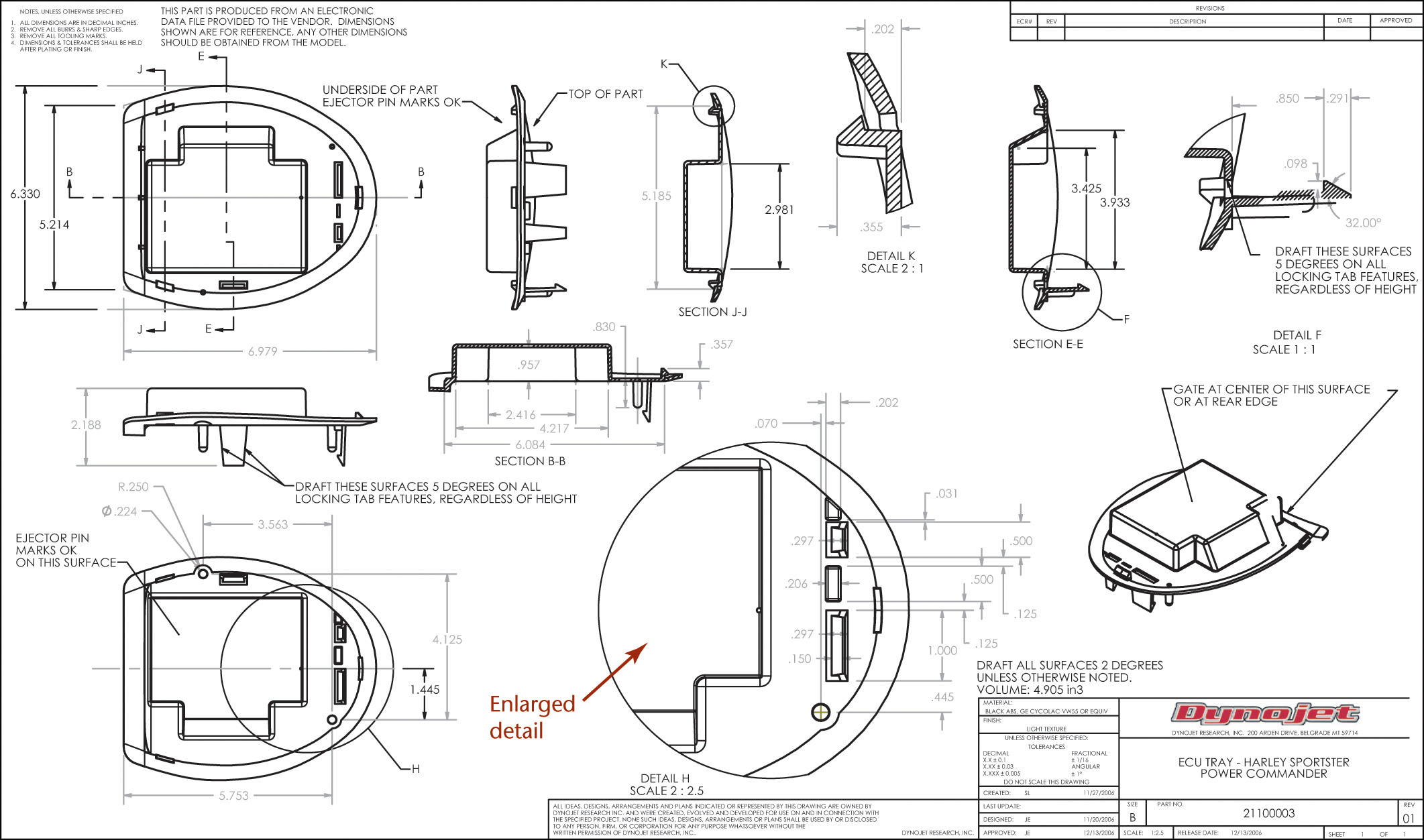
6.37 Drawing of an Injection-Molded Part with Sections and Enlarged Details (Courtesy of Dynojet Research, Inc.)
• Except for enlarged details, show all views at the same scale.
• Clearly note the difference in scale for enlarged detail views.
• Show only as many views as necessary. Do not add unnecessary views. They confuse the reader. At times additional views are needed for clear placement of dimensions. You can simplify views by leaving out hidden lines that do not add to the interpretation of the view. If you leave out lines, it is a good idea to label the view as a partial view.
Placing the Views
As you plan the views to be included, allow for plenty of white space on the drawing. Leave room for dimensions between the views, and separate the views from one another with white space. The space between drawing views does not have to be equal, yet the views should appear to be related. Do not space them too far apart. If there is not enough white space in your drawing, or if the views are too small to see the details clearly, consider using a larger sheet size (see Figure 6.38).

Isometric Views
Including isometric views in detail drawings helps others easily interpret the drawing. Isometric views are often shown in the upper right-hand area of the drawing, as there is often room there. The isometric view does not have to be at the same scale as the other views. Often, a smaller scale is just as clear and fits on the sheet better. It is not necessary to indicate the scale of the isometric view on the drawing. Figure 6.39 shows an example of an isometric view added to a part drawing. Remember that hidden lines are not usually shown in isometric views. Most modern CAD packages have preset isometric viewing directions that you can select for the model.
6.39 The isometric view provides an easy visual reference for the part described in the orthographic views.
6.6 Visualization
Along with having an understanding of the system for projecting views, you must be able interpret multiple views to picture the object that they show. In addition to being an indispensable skill to help you capture and communicate your ideas, technical sketching is also a way for others to present their ideas to you.
Even experienced engineers, technicians, and designers can’t always look at a multiview sketch and instantly visualize the object represented. You will learn to study the sketch and interpret the lines in a logical way to piece together a clear idea of the whole. This process is sometimes called visualization.
Surfaces, Edges, and Corners
To effectively create and interpret multiview projections, you have to consider the elements that make up most solids. Surfaces form the boundaries of solid objects. A plane (flat) surface may be bounded by straight lines, curves, or a combination of the two.
Practice Visualizing
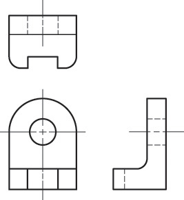
It takes practice to envision flat representations as 3D objects. Take a moment to examine the views shown in Figure 6.40 and try to picture the object. (See solution on page 258).
6.7 Views of Surfaces
A plane surface that is perpendicular to a plane of projection appears on edge as a straight line (Figure 6.41a). If it is parallel to the plane of projection, it appears true size (Figure 6.41b). If it is angled to the plane of projection, it appears foreshortened or smaller than its actual size (Figure 6.41c). A plane surface always projects either on edge (appearing as a single line) or as a surface (showing its characteristic shape) in any view. It can appear foreshortened, but it can never appear larger than its true size in any view.
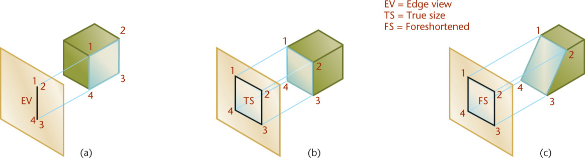
There are terms used for describing a surface’s orientation to the plane of projection. The three orientations that a plane surface can have to the plane of projection are normal, inclined, and oblique. Understanding these terms will help you picture and describe objects.
Tip: Using Numbers to Identify Vertices
Add lightly drawn numbers to your sketches to keep track of each vertex on the surface you are considering. Each vertex is unique on the part, so each numbered vertex will appear only once in each view. Sometimes two vertices will line up one behind the other, as in Figure 6.41a. When this happens you can list them in order with the closest first, as in 1, 2, or sometimes it is useful to put numbers for the closest visible vertex outside the shape, and the farthest hidden vertex inside the shape outline.
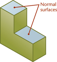
6.8 Normal Surfaces
A normal surface is parallel to a plane of projection. It appears true size and true shape on the plane to which it is parallel, and it appears as a true-length vertical or a horizontal line on adjacent planes of projection. Figure 6.42 shows an illustration of normal surfaces.
Tip
Practice identifying normal surfaces on CAD drawings. You can download orthographic views of subjects that show many normal surfaces from several websites.
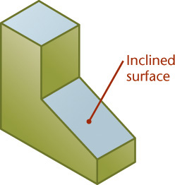
6.9 Inclined Surfaces
An inclined surface is perpendicular to one plane of projection but inclined (or tipped) to adjacent planes. An inclined surface projects on edge on the plane to which it is perpendicular. It appears foreshortened on planes to which it is inclined. An inclined surface is shown in Figure 6.43. The degree of foreshortening is proportional to the inclination. Although the surface may not appear true size in any view, it will have the same characteristic shape and the same number of edges in the views in which you see its shape.
6.10 Oblique Surfaces
An oblique surface is tipped to all principal planes of projection. Because it is not perpendicular to any projection plane, it cannot appear on edge in any standard view. Because it is not parallel to any projection plane, it cannot appear true size in any standard view. An oblique surface always appears as a foreshortened surface in all three standard views. Figures 6.44 and 6.45 show oblique surfaces.

6.11 Edges
The intersection of two plane surfaces of an object produces an edge, which shows as a straight line in the drawing. An edge is common to two surfaces, forming a boundary for each. If an edge is perpendicular to a plane of projection, it appears as a point; otherwise it appears as a line. If it is parallel to the plane of projection, it shows true length. If it is not parallel, it appears foreshortened. A straight line always projects as a straight line or as a point. The terms normal, inclined, and oblique describe the relationship of an edge to a plane of projection.
6.12 Normal Edges
A normal edge is a line perpendicular to a plane of projection. It appears as a point on that plane of projection and as a true-length line on adjacent planes of projection (Figure 6.46).

6.13 Inclined Edges
An inclined edge is parallel to one plane of projection but inclined to adjacent planes. It appears as a true-length line on the plane to which it is parallel and as a foreshortened line on adjacent planes. The true-length view of an inclined line always appears as an angled line, but the foreshortened views appear as either vertical or horizontal lines (Figure 6.47).

6.14 Oblique Edges
An oblique edge is tipped to all planes of projection. Because it is not perpendicular to any projection plane, it cannot appear as a point in any standard view. Because it is not parallel to any projection plane, it cannot appear true length in any standard view. An oblique edge appears foreshortened and as an angled line in every view (Figure 6.48).

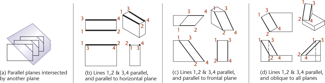
6.15 Parallel Edges
When edges are parallel to one another on the object, they will appear as parallel lines in every view, unless they align one behind the other. This information can be useful when you are laying out a drawing, especially if it has a complex inclined or oblique surface that has parallel edges. Figure 6.49 shows an example of parallel lines in drawing views.
6.16 Angles
If an angle is in a normal plane (a plane parallel to a plane of projection), it will show true size on the plane of projection to which it is parallel (Figure 6.50). If an angle is in an inclined plane, it may be projected either larger or smaller than the true angle, depending on its position. The 45° angle is shown oversize in the front view in Figure 6.50b, and the 60° angle is shown undersize in both views in Figure 6.50c.
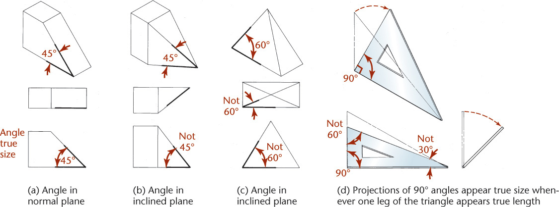
A 90° angle will project as true size, even if it is in an inclined plane, provided that one leg of it is a normal line.
In Figure 6.50d, the 60° angle is projected oversize, and the 30° angle is projected undersize. Try this on your own using a 30° or 60° triangle as a model, or even the 90° corner of a sheet of paper. Tilt the triangle or paper to look at an oblique view.
6.17 Vertices
A corner, or point, is the common intersection of three or more surfaces, which is called a vertex on the part. A point appears as a point in every view. An example of a point on an object is shown in Figure 6.51.

6.18 Interpreting Points
A point located in a sketch can represent two things:
• A vertex
• The point view of an edge (two vertices lined up one directly behind the other)
6.19 Interpreting Lines
A straight visible or hidden line in a drawing or sketch has three possible meanings, as shown in Figure 6.52:
• An edge (intersection) between two surfaces
• The edge view of a surface
• The limiting element of a curved surface

Because no shading is used on orthographic views, you must examine all the views to determine the meaning of the lines. If you were to look at only the front and top views in Figure 6.52, you might believe line AB is the edge view of a flat surface. From the right-side view, you can see that there is a curved surface on top of the object.
If you look at only the front and side views, you might believe the vertical line CD is the edge view of a plane surface. The top view reveals that the line actually represents the intersection of an inclined surface.
6.20 Similar Shapes of Surfaces
If a flat surface is viewed from several different positions, each view will show the same number of sides and a similar shape. This consistency of shapes is useful in analyzing views. For example, the L-shaped surface shown in Figure 6.53 appears L-shaped in every view in which it does not appear as a line. A surface will have the same number of sides and vertices and the same characteristic shape whenever it appears as a surface. Note how the U-shaped, hexagonal, and T-shaped surfaces in Figure 6.54 are recognizable in different views.


Practice Visualizing
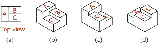
Look at the top view (a) and then examine some of the various objects it could represent. As you practice interpreting views, you will get better at visualizing 3D objects from projected views.
Notice that the top view alone does not provide all the information, but it does tell you that surfaces A, B, and C are not in the same plane. There are many possibilities beyond those shown.
6.21 Interpreting Views
One method of interpreting sketches is to reverse the mental process used in projecting them. The views of an angle bracket are shown in Figure 6.50a.
The front view (Figure 6.50b) shows the object’s L-shape, its height, and its width. The meanings of the hidden lines and centerlines are not yet clear, and you do not know the object’s depth.
The top view (Figure 6.50c) shows the depth and width of the object. It also makes it clear that the horizontal feature is rounded at the right end and has a round hole. A hidden line at the left end indicates some kind of slot.
The right-side view (Figure 6.50d) shows the height and depth of the object. It reveals that the left end of the object has rounded corners at the top and clarifies that the hidden line in the front view represents an open-end slot in a vertical position.
Each view provides certain definite information about the shape of the object, and all are necessary to visualize it completely.

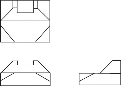
Step by Step: Reading a Drawing
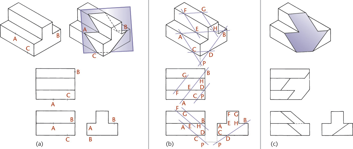
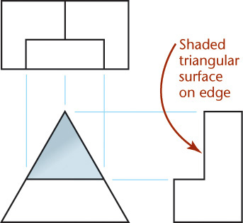
![]() Visualize the object shown by the three views at left. Because no lines are curved, the object must be made up of plane surfaces.
Visualize the object shown by the three views at left. Because no lines are curved, the object must be made up of plane surfaces.
The shaded surface in the top view is a six-sided L-shape. Because you do not see its shape in the front view—and every surface appears either as its shape or as a line—it must be showing on edge as a line in the front view. The indicated line in the front view also projects to line up with the vertices of the L-shaped surface.
Because we see its shape in the top view and because it is an angled line in the front view, it must be an inclined surface on the object. This means it will show its foreshortened shape in the side view as well, appearing L-shaped and six-sided. The L-shaped surface in the right-side view must be the same surface that was shaded in the top view.

![]() The front view shows the top portion as a triangular surface, but no triangular shapes appear in either the top or the side view. The triangular surface must appear as a line in the top view and in the side view.
The front view shows the top portion as a triangular surface, but no triangular shapes appear in either the top or the side view. The triangular surface must appear as a line in the top view and in the side view.
Sketch projection lines from the vertices of the surface where you see its shape. The same surface in the other views must line up along the projection lines. In the side view, it must be the line indicated. That can help you to identify it as the middle horizontal line in the top view.
![]() The trapezoidal surface shaded in the front view is easy to identify, but there are no trapezoids in the top and side views. Again, the surface must be on edge in the adjacent views.
The trapezoidal surface shaded in the front view is easy to identify, but there are no trapezoids in the top and side views. Again, the surface must be on edge in the adjacent views.
![]() On your own, identify the remaining surfaces using the same reasoning. Which surfaces are inclined, and which are normal? Are there any oblique surfaces?
On your own, identify the remaining surfaces using the same reasoning. Which surfaces are inclined, and which are normal? Are there any oblique surfaces?

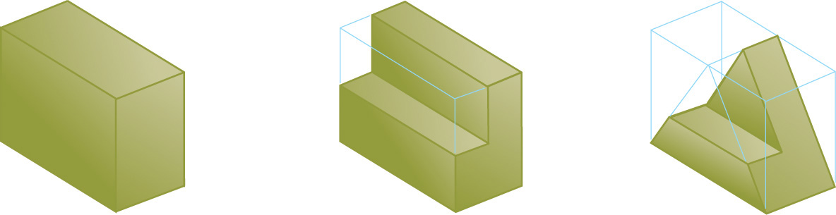
If you are still having trouble visualizing the object, try picturing the views as describing those portions of a block that will be cut away, as illustrated below.
6.22 Models
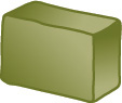
One of the best aids to visualization is an actual model of the object. Models don’t necessarily need to be made accurately or to scale. They may be made of any convenient material, such as modeling clay, soap, wood, wire, or Styrofoam, or any material that can easily be shaped, carved, or cut. Some examples of soap models are shown in Figure 6.56.

Tip: Making a Model
Try making a soap or clay model from projected views:

First, look at the three views of the object. Make your block of clay to the same principal dimensions (height, width, and depth) as shown in the views.
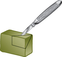
Score lines on the frontal surface of your clay block to correspond with those shown on the front view in the drawing. Then do the same for the top and right-side views.

Slice straight along each line scored on the clay block to get a 3D model that represents the projected views.
Rules for Visualizing from a Drawing: Putting It All Together
Reading a multiview drawing is like unraveling a puzzle. When you interpret a drawing, keep these things in mind:
• The closest surface to your view must have at least one edge showing as a visible line.
• A plane surface has a similar shape in any view or appears on edge as a straight line.
• Lines of the drawing represent either an intersection between two surfaces, a surface perpendicular to your view that appears “on edge,” or the limiting element of a curved surface.
• No two adjacent areas divided by a visible line in an orthographic view can be the same plane in the actual object. Areas not adjacent in a view may lie in the same plane on the object.
• If a line appears hidden, a closer surface is hiding it.
• Your interpretation must account for all the lines of the drawing. Every line has a meaning.
6.23 Projecting a Third View
Ordinarily, when you are designing a product or system, you have a good mental picture of what it will look like from different directions. However, skill in projecting a third view can be useful for two reasons. First, views must be shown in alignment in the drawing and projected correctly. Second, practice in projecting a third view from two given views is an excellent way to develop your visual abilities.
Numbering the vertices on the object makes projecting a third view easy. Points that you number on the drawing represent points on the object where three surfaces come together to form a vertex (and sometimes a point on a contour or the center of a curve).
Once you have located a point in two drawing views, its location in the third view is known. In other words, if a point is located in the front and top view, its location in the side view is a matter of projecting the height of the point in the glass box from the front view and the depth of the point in the glass box from the top view.
To number the points or vertices on the object and show those numbers in different views, you need to be able to identify surfaces on the object. Then, project (or find) the points in each new view, surface by surface. You can use what you know about edges and surfaces to identify surfaces on the object when you draw views. This will help you interpret drawings created by others as well as project your own drawings correctly.
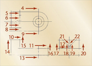
Step by Step: Manually Projecting a Third View
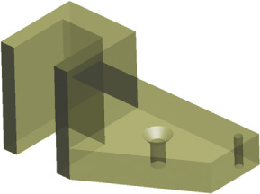
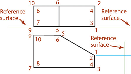
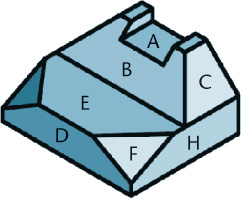
The figure below is a pictorial drawing of an object to be shown in three views. It has numbers identifying each corner (vertex) and letters identifying some of the major surfaces. You are given the top and front view. You will use point numbers to project the side view.
![]() To number points effectively, first identify surfaces and interpret the views that are given. Start by labeling visible surfaces whose shapes are easy to identify in one view. Then, locate the same surface in the adjacent view. (The surfaces on the pictorial object have been labeled to make it easier.)
To number points effectively, first identify surfaces and interpret the views that are given. Start by labeling visible surfaces whose shapes are easy to identify in one view. Then, locate the same surface in the adjacent view. (The surfaces on the pictorial object have been labeled to make it easier.)
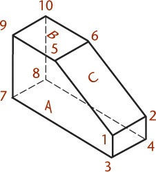
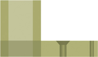
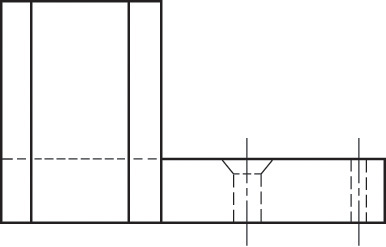
![]() Surface A in the front view is a normal surface. It will appear as a horizontal line in the top view. The two rectangular surfaces B and C in the top view are a normal surface and an inclined surface. They will show as a horizontal line and an inclined line in the front view, respectively.
Surface A in the front view is a normal surface. It will appear as a horizontal line in the top view. The two rectangular surfaces B and C in the top view are a normal surface and an inclined surface. They will show as a horizontal line and an inclined line in the front view, respectively.

![]() After identifying the surfaces, label the vertices of a surface that has an easily recognized shape, in this case, surface A.
After identifying the surfaces, label the vertices of a surface that has an easily recognized shape, in this case, surface A.

Label its vertices with numbers at each corner as shown. If a point is directly visible in the view, place the number outside the corner.
If the point is not directly visible in that view, place the numeral inside the corner. Using the same numbers to identify the same points in different views will help you project known points in two views to unknown positions in a third view.
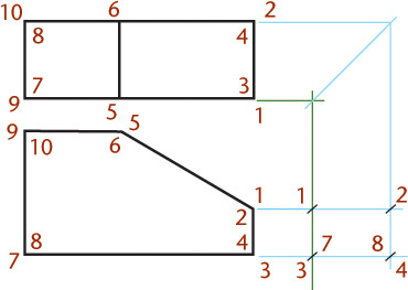
![]() Continue, surface by surface, until you have numbered all the vertices in the given views as shown. Do not use two different numbers for the same vertex.
Continue, surface by surface, until you have numbered all the vertices in the given views as shown. Do not use two different numbers for the same vertex.

![]() Try to visualize the right-side view you will create. Then, construct the right-side view point by point, using very light lines. Locate point 1 in the side view by drawing a light horizontal projection line from point 1 in the front view. Use the edge view of surface A in the top view as a reference plane to transfer the depth location for point 1 to the side view as shown.
Try to visualize the right-side view you will create. Then, construct the right-side view point by point, using very light lines. Locate point 1 in the side view by drawing a light horizontal projection line from point 1 in the front view. Use the edge view of surface A in the top view as a reference plane to transfer the depth location for point 1 to the side view as shown.
![]() Project points 2, 3, and 4 in a similar way to complete the vertical end surface of the object.
Project points 2, 3, and 4 in a similar way to complete the vertical end surface of the object.
![]() Project the remaining points using the same method, proceeding surface by surface.
Project the remaining points using the same method, proceeding surface by surface.

![]() Use the points that you have projected into the side view to draw the surfaces of the object as in this example.
Use the points that you have projected into the side view to draw the surfaces of the object as in this example.
If surface A extended between points 1-3-7-9-5 in the front view where you can see its shape clearly, it will extend between those same points in every other view.
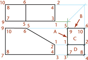
When you connect these points in the side view, they form a vertical line.
This makes sense, because A is a normal surface. As is the rule with normal surfaces, you will see its shape in one standard view (the front in this case) and it will appear as a horizontal or vertical line in the other views.
Continue connecting vertices to define the surfaces on the object, to complete the third view.
![]() Inspect your drawing to see if all the surfaces are shown, and darken the final lines.
Inspect your drawing to see if all the surfaces are shown, and darken the final lines.
Consider the visibility of surfaces. Surfaces that are hidden behind other surfaces should be shown with hidden lines.

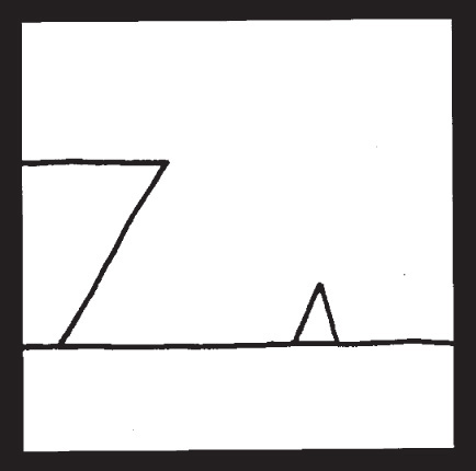
Ship Arriving Too Late to Save Drowning Witch. This well-known drawing by artist Roger Price is an example of how a single orthographic view can be difficult to interpret. (Ship Arriving Too Late to Save Drowning Witch excerpted from Droodles – The Classic Collection by Roger Price ©2000 by Tallfellow Press. Used by permission. All rights reserved.)
6.24 Becoming a 3D Visualizer
To the untrained person, orthographic projections might not convey the idea of a 3D shape, but with some practice you should now be able to look at projected front, top, and right-side views and envision that they represent the width, depth, and height of an object. Understanding how points, lines, and surfaces can be interpreted and how normal, inclined, or oblique surfaces appear from different views helps you interpret orthographic views to form a mental image of the object.
Understanding how orthographic views represent an object gives you the power to start capturing your own concepts on paper in a way that others can interpret. Keep in mind the idea of an unfolded “glass box” to explain the arrangement of views. This clarifies how the views relate to one another and why you can transfer certain dimensions from adjacent views. Using standard practices to represent hidden lines and centerlines helps you further define surfaces, features, and paths of motion.
The better you understand the foundation concepts of projected views, the more fluent you will be in the language of 3D representation and the skill of spatial thinking, regardless of whether you sketch by hand or use CAD.
Key to Figure 6.40 Normal Surfaces: A, D, E, H Inclined Surfaces: B, C Oblique Surface: F
Step by Step: Using a Miter Line
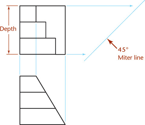
Given two completed views you can use a miter line to transfer the depths and draw the side view of the object shown at right.

![]() Locate the miter line a convenient distance away from the object to produce the desired spacing between views.
Locate the miter line a convenient distance away from the object to produce the desired spacing between views.
![]() Sketch light lines projecting depth locations for points to the miter line and then down into the side view as shown.
Sketch light lines projecting depth locations for points to the miter line and then down into the side view as shown.
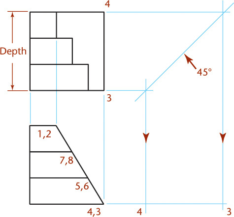
![]() Project the remaining points.
Project the remaining points.
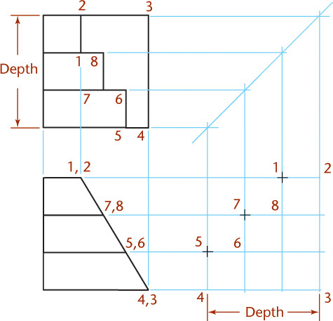
![]() Draw the view by locating each vertex of the surface on the projection line and across the miter line.
Draw the view by locating each vertex of the surface on the projection line and across the miter line.
To move the right-side view to the right or left, move the top view upward or downward by moving the miter line closer to or farther from the view. You don’t need to draw continuous lines between the top and side views via the miter line. Instead, make short dashes across the miter line and project from these. The 45° miter-line method is also convenient for transferring a large number of points, as when plotting a curve.


Top, Front, and Bottom Views of a Mirror Retainer. The bottom view is shown for ease of dimensioning. (Courtesy of Big Sky Laser.)
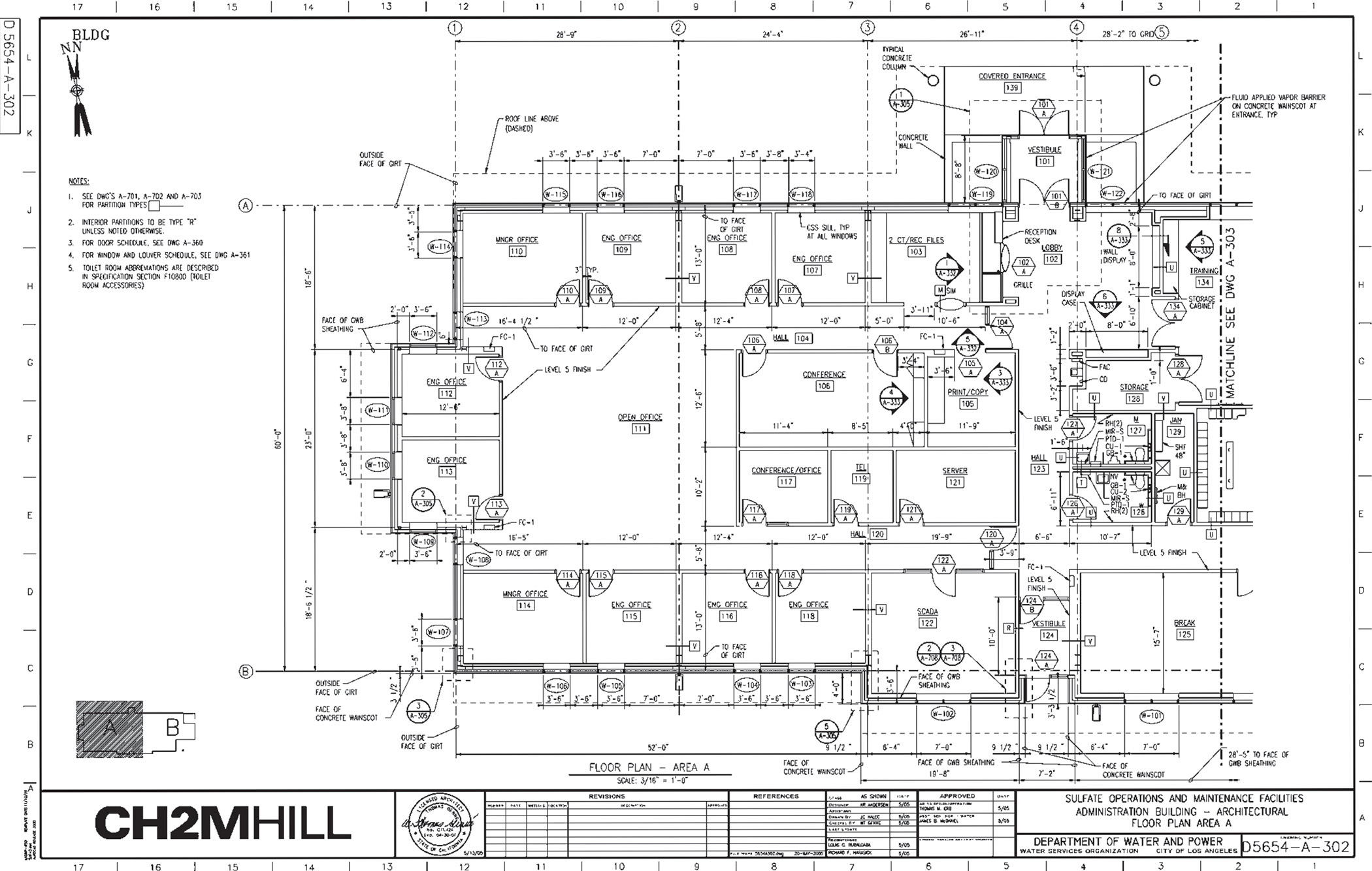
Architectural floor plans show the building as though the roof were cut off and the top orthographic view was projected. (Courtesy of CH2M HILL.)
Chapter Summary
• Orthographic drawings are the result of projecting the image of a 3D object onto one of six standard planes of projection. The six standard views are often thought of as an unfolded glass box. The arrangement of the views in relation to one another is important. Views must line up with adjacent views, so that any point in one view projects to line up with that same point in the adjacent view. The standard arrangement of views shows the top, front, and right side of the object.
• Visualization is an important skill. You can build your visual abilities through practice and through understanding terms describing objects. For example, surfaces can be normal, inclined, or oblique. Normal surfaces appear true size in one principal view and as an edge in the other two principal views. Inclined surfaces appear as an edge in one of the three principal views. Oblique surfaces do not appear as an edge in any of the principal views.
• Choice of scale is important for representing objects clearly on the drawing sheet.
• Hidden lines are used to show the intersections of surfaces, surfaces that appear on edge, and the limits of curved surfaces that are hidden from the viewing direction.
• Centerlines are used to show the axis of symmetry for features and paths of motion, and to indicate the arrangement for circular patterns.
• Creating CAD drawings involves applying the same concepts as in paper drawing. The main difference is that drawing geometry is stored more accurately using a computer than in any hand drawing. CAD drawing geometry can be reused in many ways and plotted to any scale as necessary.
Review Questions
1. Sketch the symbol for third-angle projection.
2. List the six principal views of projection.
3. Sketch the top, front, and right-side views of an object of your design having normal, inclined, and oblique surfaces.
4. In a drawing that shows the top, front, and right-side view, which two views show depth? Which view shows depth vertically on the sheet? Which view shows depth horizontally on the drawing sheet?
5. What is the definition of a normal surface? An inclined surface? An oblique surface?
6. What are three similarities between using a CAD program to create 2D drawing geometry and sketching on a sheet of paper? What are three differences?
7. What dimensions are the same between the top and front view: width, height, or depth? Between the front and right-side view? Between the top and right-side view?
8. List two ways of transferring depth between the top and right-side views.
9. If surface A contains corners 1, 2, 3, 4, and surface B contains 3, 4, 5, 6, what is the name of the line where surfaces A and B intersect?
Chapter Exercises
The multiview projection exercises are intended to be sketched freehand on graph paper or plain paper. Sheet layouts such as A1, found inside the front cover, are suggested, but your instructor may prefer a different sheet size or arrangement. Use metric or decimal inch as assigned. The marks shown on some exercises indicate rough units of either 1/2″ and 1/4″ (or 10 mm and 5 mm). All holes are through holes. If dimensions are required, study Chapter 11, and use metric or decimal-inch dimensions as assigned by the instructor.
Example Exercise
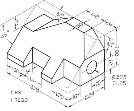
Exercise 6.1 Spacer. Draw or sketch all necessary views.
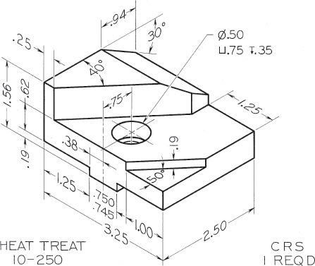
Exercise 6.2 Slide. Draw or sketch all necessary views.
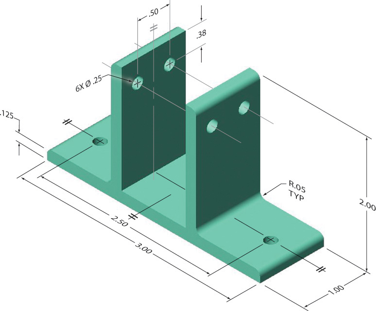
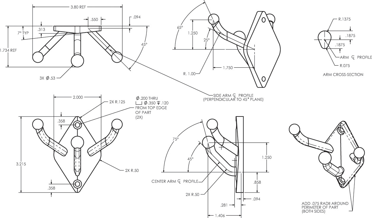
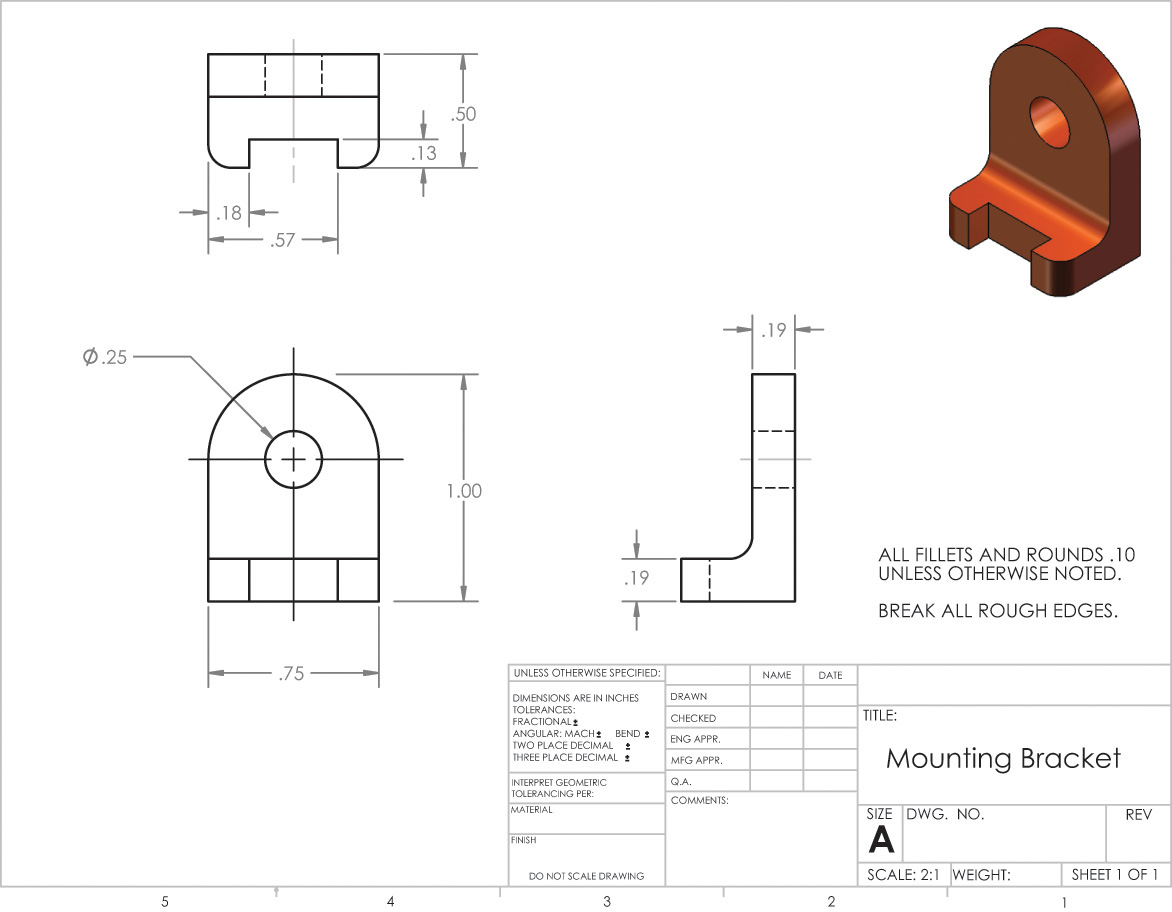
Exercise 6.3 Wall Bracket. Create a drawing with the necessary orthographic views for the wall bracket.

Exercise 6.4 Sheet Metal Bracket. Create a drawing of the necessary orthographic views for the sheet metal bracket.

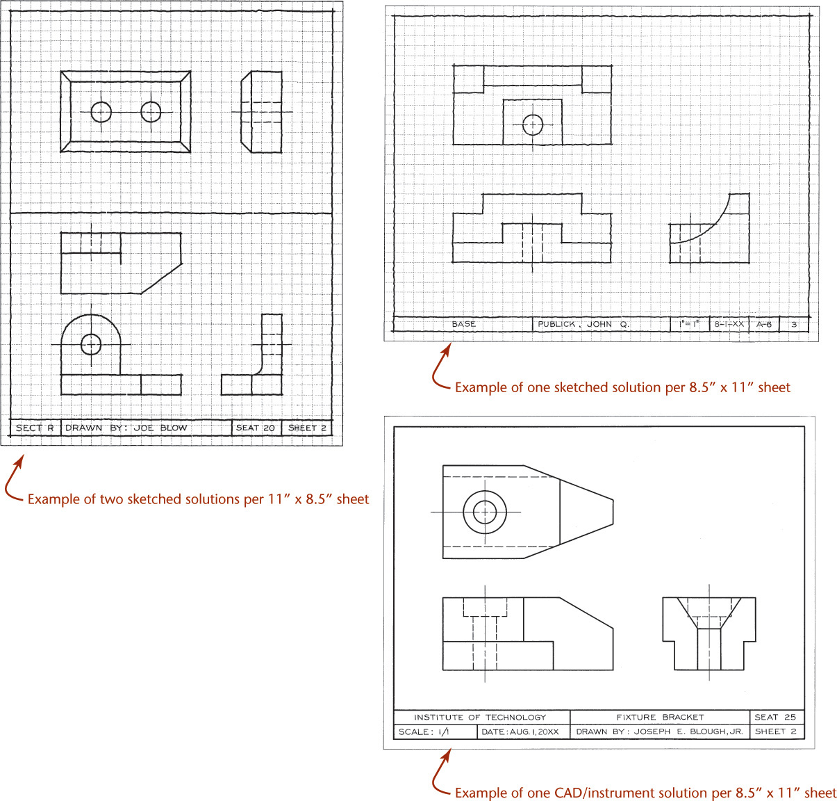
Exercise 6.5 Multiview Sketching Problems. Sketch necessary orthographic views on graph paper or plain paper, showing either one or two problems per sheet as assigned by your instructor. These exercises are designed to fit on 8.5″ × 11″ size A or metric A4 paper. The units shown may be either .500″ and .250″ or 10 mm and 5 mm. All holes are through holes.
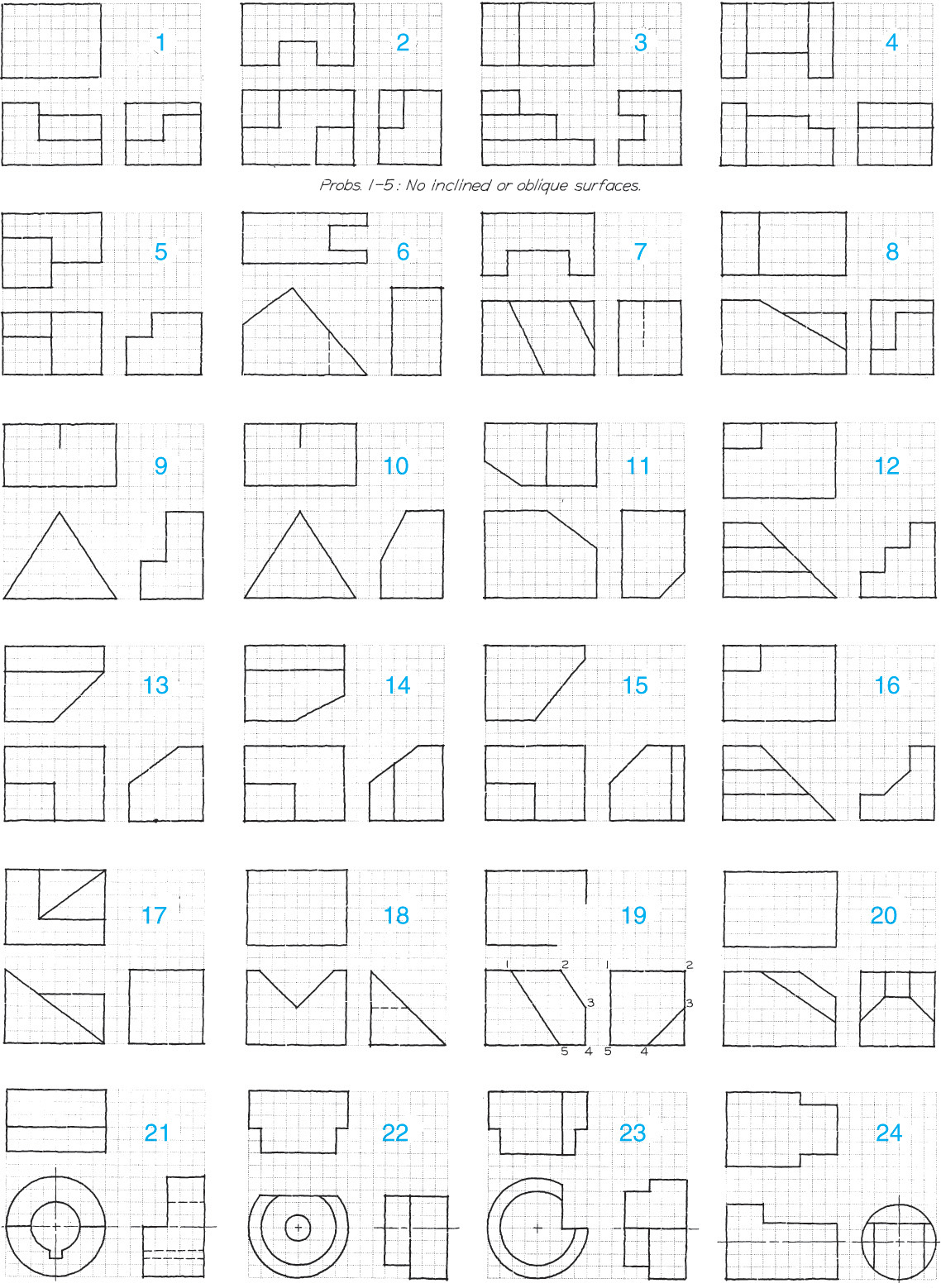
Exercise 6.6 Missing-Line Sketching Problems. (1) Sketch the given views on graph paper or plain paper showing either one or two problems per sheet as assigned by your instructor. See the examples at the beginning of this chapter’s exercises. These exercises are designed to fit on 8.5″ × 11″ size A or metric A4 paper. Add the missing lines. The squares may be either .250″ or 5 mm. (2) Sketch in isometric on isometric paper or in oblique on cross-section paper, if assigned.

Exercise 6.7 Third-View Sketching Problems. Sketch the given views and add the missing views as indicated on graph paper or plain paper. These exercises are designed to fit on 8.5″ × 11″ size A or metric A4 paper. The squares may be either .25″ or 5 mm. The given views are either front and right-side views or front and top views. Hidden holes with centerlines are drilled holes.

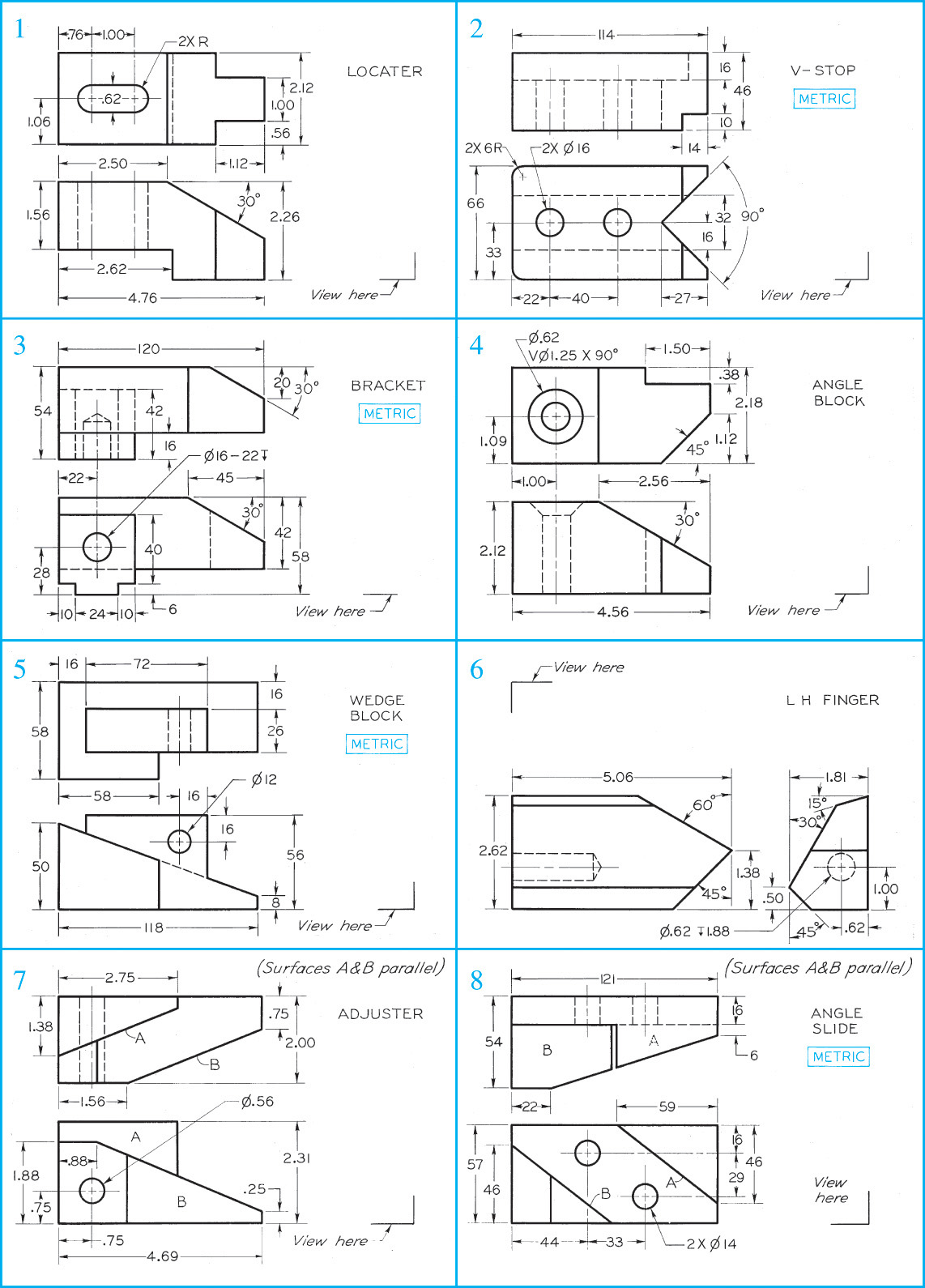
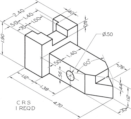
Exercise 6.8 Missing-View Problems. Sketch or draw the given views, and add the missing view. If dimensions are required, study Chapter 11. These exercises are designed to fit on 8.5″ × 11″ size A or metric A4 paper. Use metric or decimal-inch dimensions as assigned by the instructor. Move dimensions to better locations where possible. In problems 1–5, all surfaces are normal surfaces.
Exercise 6.9 Missing-View Problems. Sketch or draw the given views, and add the missing view. These exercises are designed to fit on 8.5″ × 11″ size A or metric A4 paper. If dimensions are required, study Chapter 11. Use metric or decimal-inch dimensions as assigned by the instructor. Move dimensions to better locations where possible.

Exercise 6.10 Missing-View Problems. Sketch or draw the given views, and add the missing view. These exercises are designed to fit on 8.5″ × 11″ size A or metric A4 paper. If dimensions are required, study Chapter 11. Use metric or decimal-inch dimensions as assigned by the instructor. Move dimensions to better locations where possible.
Exercise 6.11 Safety Key. Draw the necessary orthographic views on 8.5″ × 11″ size A or metric A4 paper. Use a title block or title strip as assigned by your instructor.
Exercise 6.12 Tool Holder. Draw the necessary orthographic views on 8.5″ × 11″ size A or metric A4 paper. Use a title block or title strip as assigned by your instructor.
Exercise 6.13 Index Feed. Draw the necessary orthographic views on 8.5″ × 11″ size A or metric A4 paper. Use a title block or title strip as assigned by your instructor.

Exercise 6.14 Finger Guide. Draw the necessary orthographic views on 8.5″ × 11″ size A or metric A4 paper. Use a title block or title strip as assigned by your instructor.
Exercise 6.15 Draw the views as shown. Omit all dimensions.
Exercise 6.16 Draw the views as shown. Omit all dimensions.

Exercise 6.17 Draw views of the seal cover. Omit the dimensions and notes.

Exercise 6.18 Model each of the parts shown. Before starting, carefully consider which feature to use as the base feature and how you will create the model so it will be updated as specified.
a. Design intent: The length and width of the slot must be able to change to accommodate fit with a different part. The four holes must remain equally spaced around the wider/longer slot.
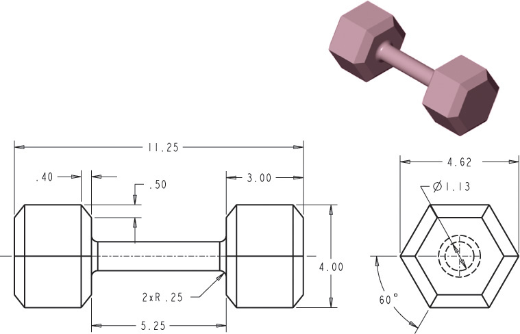
b. Model the hand weight shown. Determine the weight if this part is cast from ASTM class 20 gray iron. Update the model to create a set of three hand weights of different weights, but maintain the diameter and length of the crossbar grip.
c. Model the part so that as the overall height, width, depth of the part are changed the other features are updated proportionally to them.

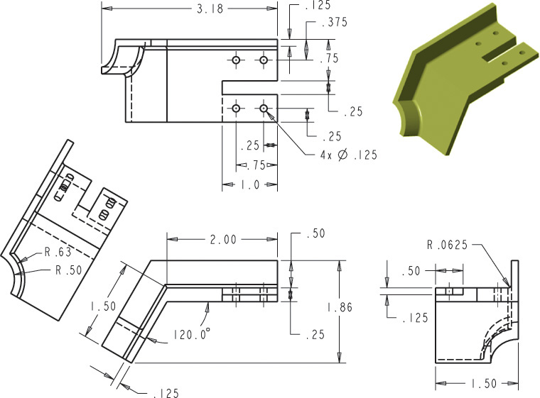
d. Create a model for the decorative corner cap shown.

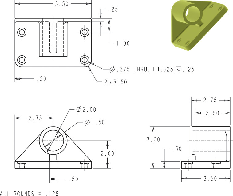
e. Model the rail bracket shown so that the diameter for the central hole can change to accommodate different diameters of railing. The height, width, and depth for the bracket should remain the same when the central hole size is updated. The mounting holes should also remain the original size.
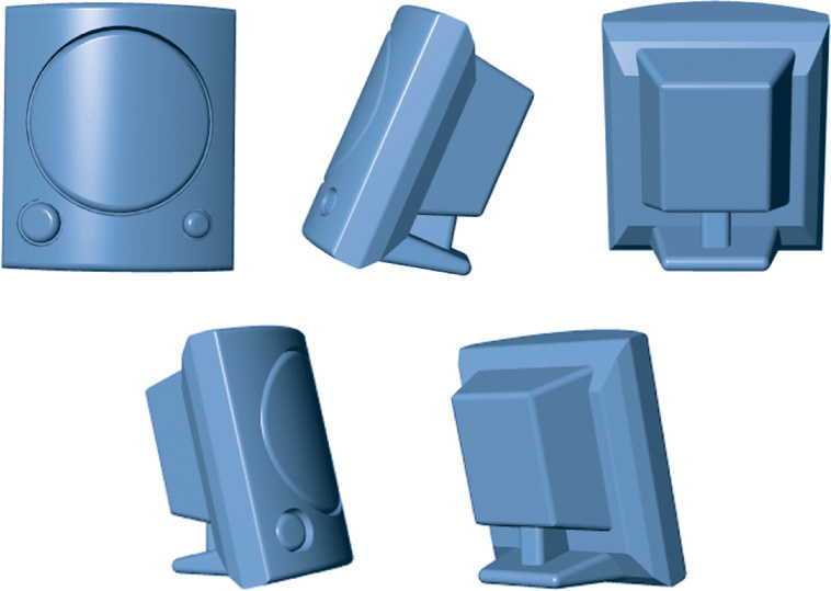
f. Model the plastic speaker housing shown. Start by sketching the speaker housing and noting the dimensions that will control the shape. Once you have a sketch, use your sketched plan to model the speaker housing according to your plan.
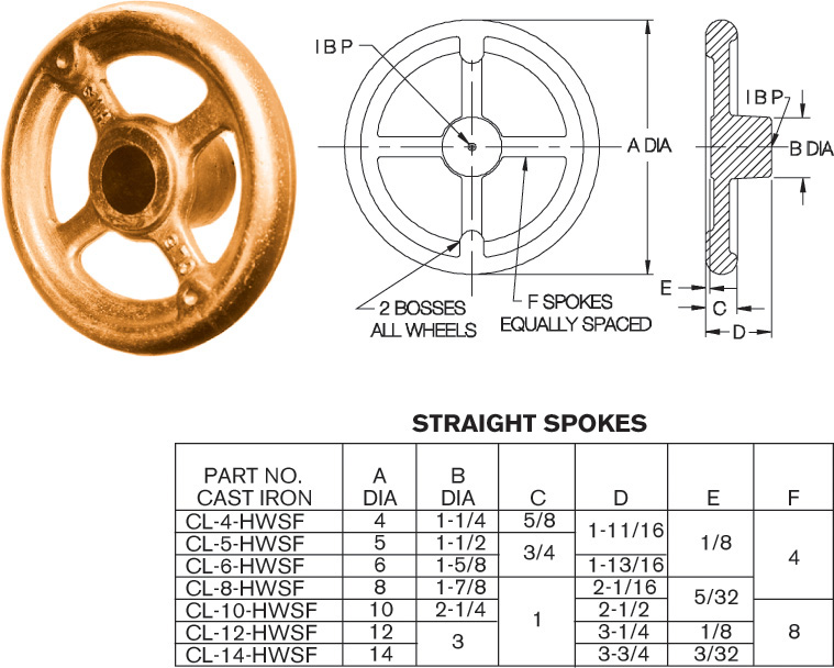
Exercise 6.19 Create a constraint-based model of the four-spoke hand wheel shown such that it can be resized to match the dimensions in the table.
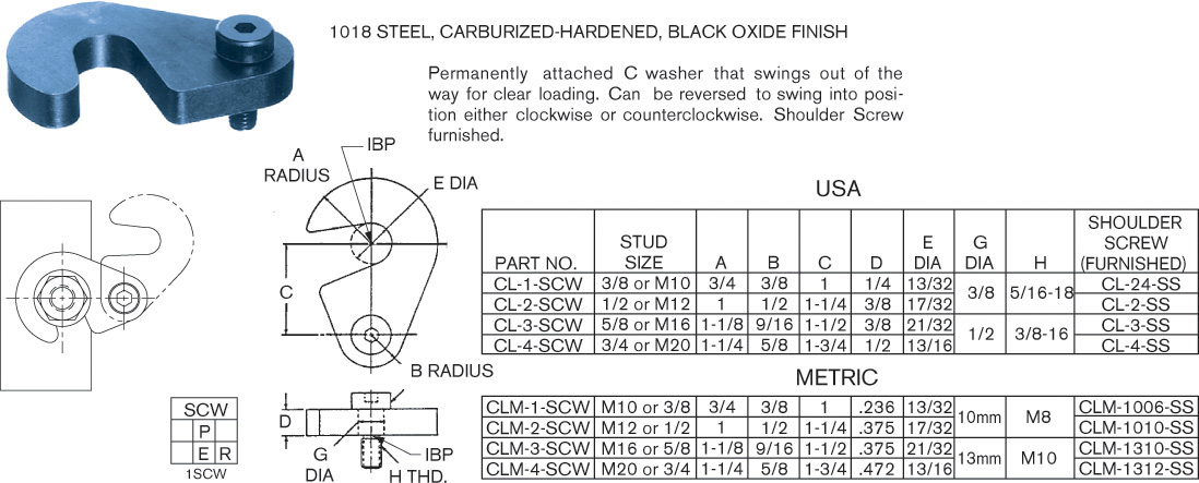
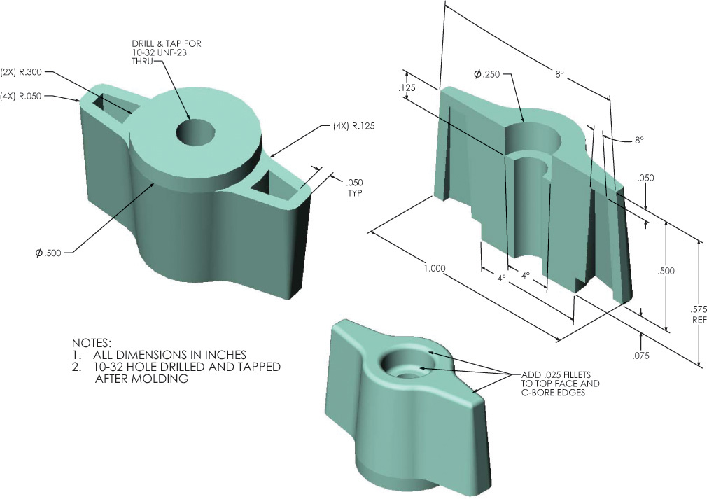
Exercise 6.20 Create a constraint-based model of the swing washer shown such that it can be resized to match the dimensions in the table. Capture size relationships between features in the constraint-based dimensions wherever possible.
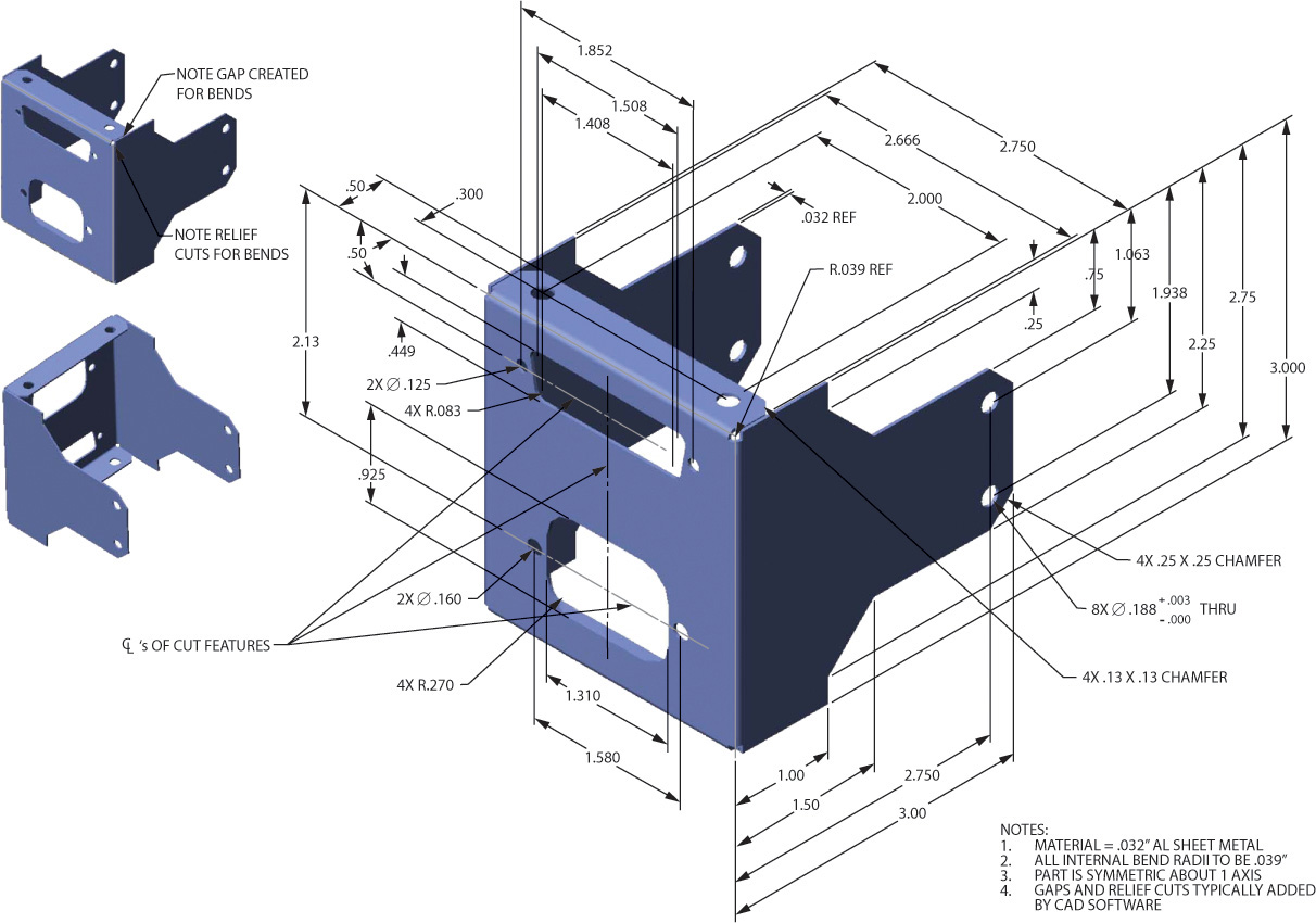
Exercise 6.21 Create a constraint-based model of the electronics bracket shown.
Exercise 6.22 Create a constraint-based model of the gyroscope base shown.
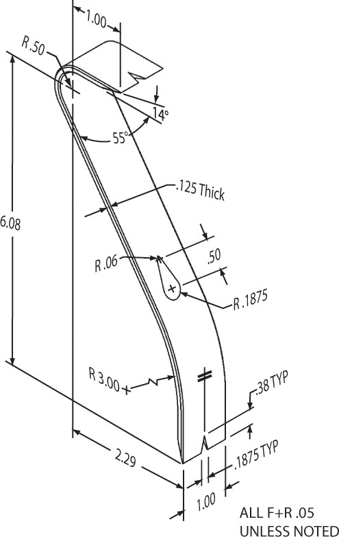
Exercise 6.23 Create a constraint-based model of the pry bar shown.
Exercise 6.24 Create a constraint-based model of this ice cube tray.

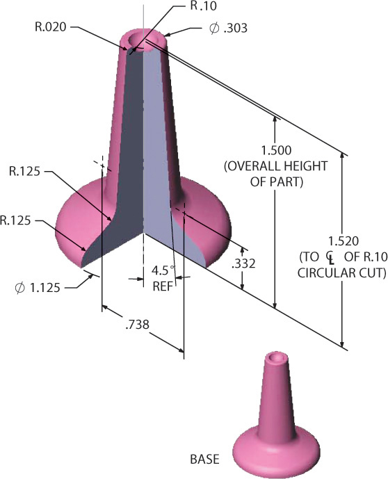
Exercise 6.25 Create a constraint-based model of this simple knob.
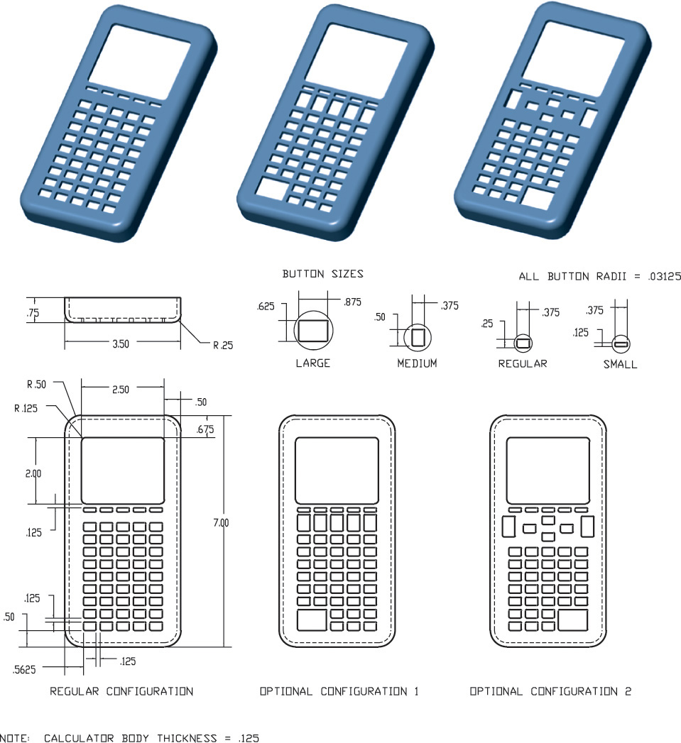
Exercise 6.26 Create a constraint-based model of the first part in each set, save the part, then edit the part to create the other configurations in each set. Save all part files.
a. Saw Blade

b. Calculator

d. Brace

Exercise 6.27 Create a constraint-based model of the wall hanger.