After studying the material in this chapter, you should be able to:
1. Represent curved surfaces in multiview drawings.
2. Show intersections and tangencies of curved and planar surfaces.
3. Represent common types of holes.
4. Show fillets, rounds, and runouts in a 2D drawing.
5. Use partial views.
6. Apply revolution conventions when necessary for clarity.
7. Show removed views and projected views.
8. Show right- and left-hand parts.
9. Project curved surfaces by points.
10. Show and label an enlarged detail.
11. Show conventional breaks.
Refer to the following standards:
• ANSI/ASME Y14.3 Multiview and Sectional View Drawings
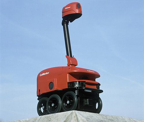
The CoWorker robot is a 3′-high Pentium powered robot that can provide a mobile telepresence in remote locations. The CoWorker is made by the iRobot Corporation. (Courtesy of Sam Ogden/Photo Researchers, Inc.)
Overview
An object with molded plastic parts like the one shown above has curved surfaces on inside and outside corners to make it easier to remove the part from the mold. There are a number of practices for showing curved surfaces in your drawings.
Learning the names of typical features and hole types that are used in part design and how they are represented in drawing views will make it easier for you to communicate about designs and to understand their documentation requirements.
At times, conventional practices are used that are not standard orthographic projections. This is to make it easier to represent or interpret objects in drawings. An example is revolving certain features when it adds to the clarity of the drawing. Another example is showing “breaks” when a part does not fit well on the sheet because of its long shape, or to avoid unnecessary detail.
There is an art to creating drawings that show the information clearly and provide all the detail necessary to manufacture it. People can read drawings most easily when views, dimensions, and lines are placed in logical locations that aid in the reader’s comprehension of the part and the design intent for the part.
Practices for 2D Documentation Drawings
Now that you are familiar with the basics of orthographic projection and visualizing objects from the information presented in orthographic views, you are ready to make and read more complex 2D drawings. Although you might sketch complex designs by hand, it is more likely that you would create these types of drawings using CAD, either as 2D CAD drawings, or as 2D CAD drawings generated from a 3D solid model.
Sometimes, practices used to create drawings with 3D CAD differ from those used to create hand-drawn or 2D CAD drawings. You must understand the standards and practices for creating good drawings even when using 3D CAD. The software will not do everything for you.
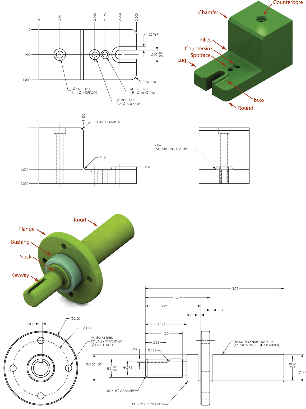
Common Manufactured Features
Certain features are a part of many engineering designs. Learning their names and shapes, as shown in Figure 7.1 and detailed in Table 7.1, helps you visualize and communicate about them. Some CAD systems may even have prebuilt features that you can place onto a 3D part to create them quickly.
7.1 Commonly Manufactured Features
Table 7.1 Common Manufactured Features
Feature
Example
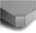
Fillet: A rounded interior blend between surfaces; used, for example, to strengthen adjoining surfaces or to allow a part to be removed from a mold
Round: A rounded exterior blend between surfaces; used to make edges and corners easier to handle, improve strength of castings, and allow for removal from a mold
Counterbore: A cylindrical recess around a hole, usually to receive a bolt head or nut
Countersink: A cone-shaped recess around a hole, often used to receive a tapered screw head
Spotface: A shallow recess like a counterbore, used to provide a good bearing surface for a fastener
Boss: A short raised protrusion above the surface of a part, often used to provide a strong flat bearing surface
Lug: A flat or rounded tab protruding from a surface, usually to provide a method for attachment
Flange: A flattened collar or rim around a cylindrical part to allow for attachment
Chamfer: An angled surface, used on a cylinder to make it easier to start into a hole, or a plate to make it easier to handle
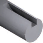
Neck: A small groove cut around the diameter of a cylinder, often where it changes diameter
Keyway/Keyseat: A shaped depression cut along the axis of a cylinder or hub to receive a key, used to attach hubs, gears, and other parts to a cylinder so they will not turn on it
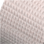
Knurl: A pattern on a surface to provide for better gripping or more surface area for attachment, often used on knobs and tool handles
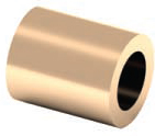
Bushing: A hollow cylinder that is often used as a protective sleeve or guide, or as a bearing
Conventional Representationsc
Standard orthographic projections don’t always show complex shapes as clearly and simply as you may wish, so certain alternative practices, referred to as conventions, are accepted. Although “convention” is usually a general term for an accepted method, in the case of technical drawing it refers particularly to a simplified representation that enhances economy and clarity in a drawing. Although conventional representations do deviate from true orthographic projection, their methods of simplification are generally recognized and accepted. (See ASME Y14.3.) In other words, conventions are like rules for breaking the rules.
Intersections and Tangencies
To represent complex objects, multiview drawings use standard methods for depicting the way planar and curved surfaces meet. A plane surface can intersect or be tangent to a contoured surface, as shown in Figures 7.2 and 7.3. When a plane surface intersects the contoured surface, a line is drawn to represent the edge formed by that intersection. When the plane surface is tangent to the contoured surface, no line or a thin phantom line pattern is drawn where the surfaces meet, depending on whether the phantom line is needed to aid in visualization.
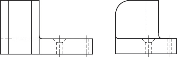
7.2 Intersecting and Tangent Surfaces
7.3 Orthographic Views of Intersecting and Tangent Surfaces
Removed Views
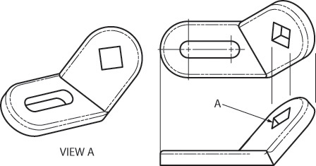
It is not always possible to show all the drawing views in alignment on the sheet. This is particularly true of civil and architectural drawings where the size and complexity of the object make it hard to show the level of detail necessary and still fit the views on one sheet. When this is the case, a removed view can be used. There are two different ways to indicate the viewing direction for removed views. One is to use a view indicator arrow to show the direction of sight, as shown in Figure 7.4a. The other is to use a viewing plane line, as shown in Figure 7.4b. Clearly label the removed view.
7.4 Indicating Removed Views
7.1 Visualizing and Drawing Complex Cylindrical Shapes
The illustrations in Figure 7.5 show how to visualize cylindrical features being cut from a rectangular block (prism). Compare each illustration showing the material being removed with the drawing.
7.5 Visualizing and Drawing Cylindrical Shapes
In Figure 7.5a there is no line where the contoured surface of the rounded top joins the straight planar sides. The top view appears as a rectangle. The centerline for the rounded top is shown in all three views. Consider these questions as you look at Figure 7.5a:
• In this drawing, how many views are necessary?
• Which views are repetitive?
• Is the centerline required to locate the rounded top?
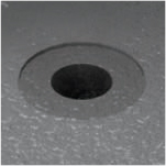
In Figure 7.5b, the material for the center hole is removed. Then, hidden lines are added to the top and side view showing the limiting elements of the cylindrical hole. As you look at Figure 7.5b note:
• In the front view the hole appears round.
• The centerlines in the drawing locate the hole as well as the rounded top, since they are concentric.
In Figure 7.5c the counterbored holes are created. As you look at Figure 7.5c ask yourself:
• How many lines are used to show the counterbore in the side and top views?
• How many views are necessary?
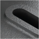
In Figure 7.5d a portion of the top surface is removed. Notice how those lines appear in the top and side views. How many views are necessary now?
In Figure 7.5c, the side view or top view or a note specifying the depth of the counterbore is needed. The counterbore is five lines.
In Figure 7.5d the top or side view or a note is required. The side view is probably a better choice, because it shows more about the shape than the top view.
7.2 Cylinders when Sliced
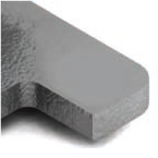
Cylinders are often machined to form plane or other types of surfaces. Figure 7.6a shows a single machined cut that created two normal surfaces. Normal surfaces appear true shape in the view where the line of sight is perpendicular to the surface. In the two other views that normal surface appears on edge. The back half remains unchanged.
7.6 Showing Views of Cylinders with Planar Surfaces Cut Away
In Figure 7.6b, two stepped cuts form four normal surfaces. Note that surface 7–8 (top view) is through the center of the cylinder, producing in the side view line 21–24 and in the front view surface 11–14–16–15, which is equal in width to the diameter of the cylinder. Surface 15–16 (front view) shows in the top view as 7–8–Arc 4. Surface 11–14 (front view) shows in the top view as 5–6–Arc 3–8–7–Arc 2.
Figure 7.6c shows a part with two coaxial cylindrical features, which is cut to form a normal surface parallel to the axis of the cylinders.
StepbyStep:Plotting Curves by Hand
Example 1
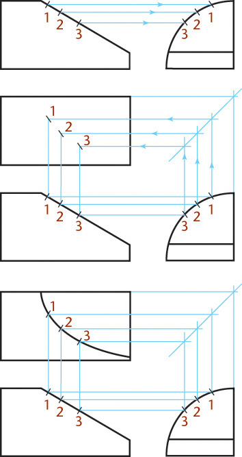
Steps 1–3 apply to both illustrated examples.
Given the front and right-side view, project the correct view of the curve into the top view. Break up the curve into several points and locate them in the adjacent view.
Project the points along projection lines into the top view from the front view. Transfer the depth from the side view, using the back surface as a reference plane.
Draw the curve through the points.
Example 2
7.3 Cylinders and Ellipses
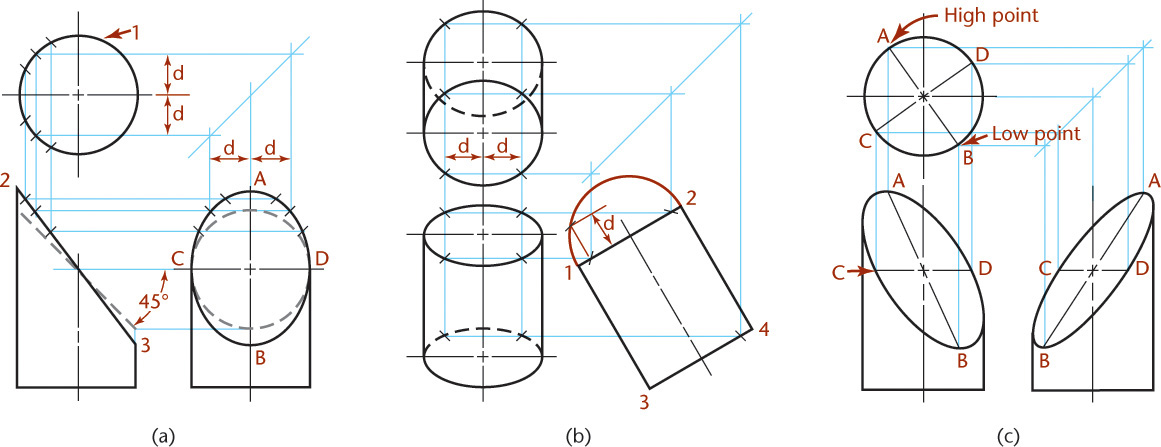
If a cylinder is cut by an inclined plane, as shown in Figure 7.7a, the inclined surface is bounded by an ellipse. This ellipse will appear as a circle in the top view, as a straight line in the front view, and as an ellipse in the side view. Note that circle 1 appears circular in the top view regardless of the angle of the cut. If the cut is at 45° from horizontal, it would also appear as a circle in the side view.
7.7 Elliptical Surfaces on Cylinders
When a circular shape is shown inclined in another view and projected into the adjacent view as shown in Figure 7.7b, it will appear as an ellipse, even though the shape is a circle. The inclined ellipse in Figure 7.7c is not shown true size and shape in any of the standard views given. You will learn in Chapter 9 how to create auxiliary views to show the true size and shape of inclined surfaces like these.
7.4 Intersections and Tangencies
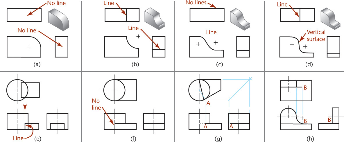
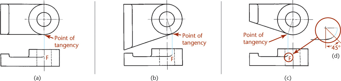
Where a curved surface is tangent to a plane surface (Figure 7.8a) no line is drawn, but when it intersects a plane surface, as in Figure 7.8b, a definite edge is formed.
7.8 Intersections and Tangencies
Figure 7.8c shows that when curves join each other or plane surfaces smoothly (i.e., they are tangent) a line is not drawn to show where they come together. If a combination of curves creates a vertical surface, as in Figure 7.8d, the vertical surface is shown as a line (here in the top view).
When plane surfaces join a contoured surface, a line is not shown if they are tangent, but is shown if they intersect. Figures 7.8e–h show examples of planes joining contoured surfaces.
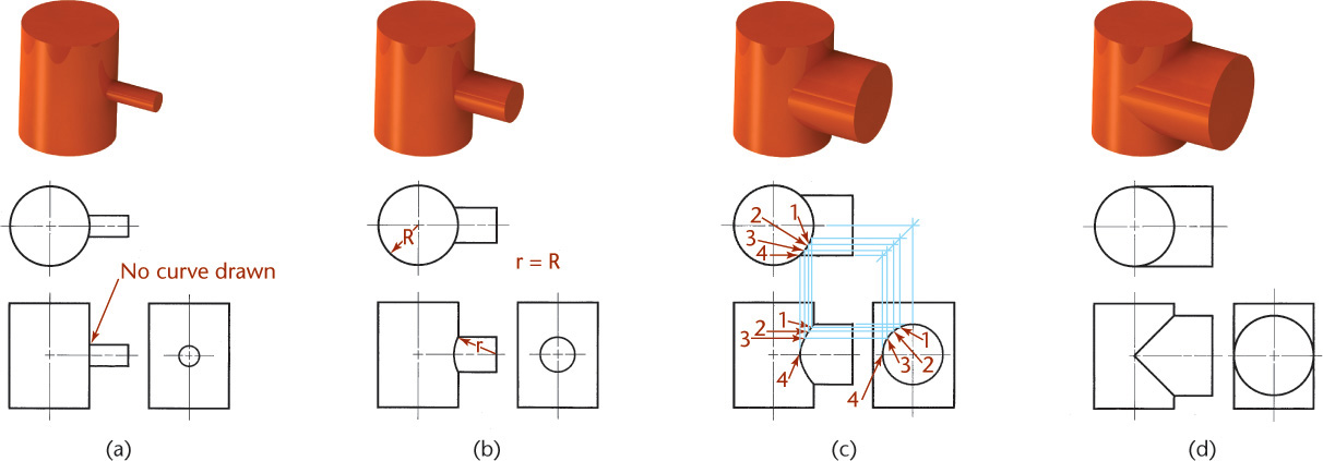
Intersections of Cylinders
Figure 7.9a shows an example of a small cylinder intersecting a large cylinder. When the intersection is small, its curved shape is not plotted accurately because it adds little to the sketch or drawing for the time it takes. Instead it is shown as a straight line.
7.9 Intersections of Cylinders
When the intersection is larger, it can be approximated by drawing an arc with the radius the same as that of the large cylinder, as shown in Figure 7.9b.
Large intersections can be plotted accurately by selecting points along the curve to project, as shown in Figure 7.9c.
Tip
Using CAD tools you can locate the center and points on the major and minor axis and use the CAD software’s ellipse tool to draw the whole ellipse through the points. Then, trim off the extra portion.
A similar technique works when using a template.
When the cylinders are the same diameter, their intersections appear as straight lines in the adjoining view, as shown in Figure 7.9d. When you are using 3D modeling, the accurate intersection of the surfaces is typically represented (see Figure 7.10).
7.10 Intersections. (a) and (b) Examples of a narrow prism intersecting a cylinder. (c) and (d) Intersections of a keyseat and cylinder and a small hole and cylinder.
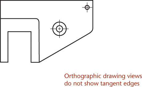
CADatWork:To Show or Not to Show: Tangent Surfaces in Solid Models
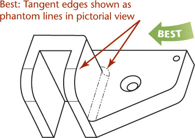
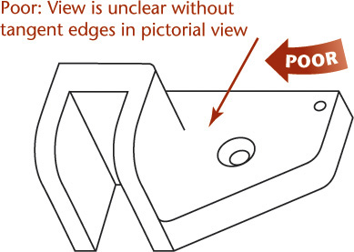
When you are creating solid models of contoured surfaces, it can be very useful to show the “tangent edges” where the contoured surface intersects the model. These lines that depict where the contoured surface ends and where the planar surface begins are not typically drawn in orthographic drawing views, unless the drawing might be confusing without them. When it is necessary to show the tangent edges, use a phantom line for them.
Using a phantom line to show the tangent edges of the model in the pictorial view is often necessary on parts that have many fillets and rounds; otherwise, the view generated by the software may not show the part clearly.
Most CAD software allows you to set the display of tangent edges both for the entire drawing and for individual views.
Even when you are creating drawings using a CAD system you should follow standard drawing conventions. Knowing your CAD software well is important so that you can manage settings like those for tangent edges to show your drawing clearly.
7.5 Fillets and Rounds
A rounded interior corner is called a fillet. A rounded exterior corner is called a round (Figure 7.11a). Sharp corners are usually avoided in designing parts to be cast or forged because they are difficult to produce and can weaken the part.
7.11 Rough and Finished Surfaces
Two intersecting rough surfaces produce a rounded corner (Figure 7.11b). If one of these surfaces is machined, as shown in Figure 7.11c, or if both surfaces are machined, as shown in Figure 7.11d, the corner becomes sharp. In drawings, a rounded corner means that both intersecting surfaces are rough. A sharp corner means that one or both surfaces are machined. Do not shade fillets and rounds on multiview drawings. The presence of the curved surfaces is indicated only where they appear as arcs, unless it is done to call attention to them.
3D CAD software varies in its ability to create complex blends for fillets and rounds. Figure 7.12 shows a CAD model with complex fillets. Figure 7.13 shows complex 3D CAD rounds.
7.12 Fillets on a CAD Model (Courtesy of Ross Traeholt.)
7.13 Rounds on a CAD Model of a Design for a Three-Hole Punch(Courtesy of Douglas Wintin.)
7.6 Runouts
Small curves called runouts are used to represent fillets that connect with plane surfaces tangent to cylinders, as shown in Figures 7.14a–d. The runouts should have a radius equal to that of the fillet and a curvature of about one eighth of a circle, as shown in Figure 7.15c. Figures 7.14e–n show more examples of conventional representations for fillets, rounds, and runouts.
7.14 Conventional Fillets, Rounds, and Runouts
7.15 Runouts
Runouts from different filleted intersections will appear different owing to the shapes of the horizontal intersecting members. In Figures 7.14e and 7.14f, the runouts differ because the top surface of the web is flat in Figure 7.14e, whereas the top surface of the web in Figure 7.14f is considerably rounded.
When two different sizes of fillets intersect, the direction of the runout is dictated by the larger fillet, as shown in Figures 7.14g and 7.14j.
7.7 Conventional Edges
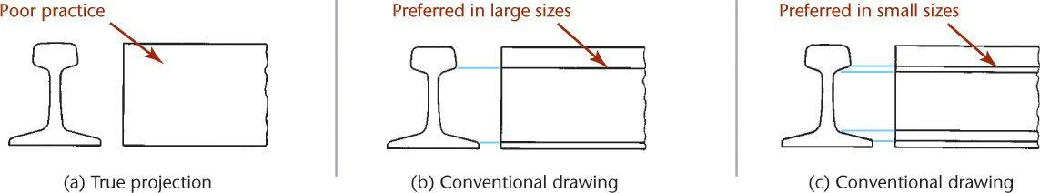
Rounded and filleted intersections eliminate sharp edges and can make it difficult to present the shape clearly. In some cases, as shown in Figure 7.16a, the true projection may be misleading. There is a conventional way of showing rounded and filleted edges for the sake of clarity. Added lines depicting rounded and filleted edges, as shown in Figures 7.16b and 7.16c, give a clearer representation, even though it is not the true projection. Project the added lines from the intersections of the surfaces as if the fillets and rounds were not present.
7.16 Conventional Representation of a Rail
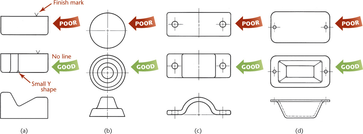
Figure 7.17 shows top views for each given front view. The first set of top views have very few lines, even though they are the true projection. The second set of top views, where lines are added to represent the rounded and filleted edges, are quite clear. Note the use of small Y shapes where rounded or filleted edges meet a rough surface. If an edge intersects a finished surface, no Y shape is shown.
What are the absolutely minimum views required to completely define an object?
As you have already seen, sometimes only a single view with a note about the part’s thickness is enough to define the shape (Figure 7.18). Sometimes two views are required (Figure 7.19). For complex parts three or more views may be required (Figure 7.20).
7.18 One-View Drawing
7.19 Two-View Drawing
7.20 Three-View Drawing
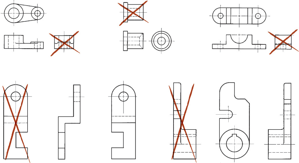
In each set of views shown in Figure 7.21, three views are shown, but only two of the three are required.
When deciding which views to show, keep in mind the following:
• Show sufficient views to completely describe the shape.
• Show the right-hand view instead of the left-hand view if both show the object equally well.
• Choose the top view rather than the bottom view.
• Show long parts horizontally on the sheet for two reasons: (1) they fit better; (2) they tend to appear even longer when shown vertically.
• Make it your goal to communicate the information clearly. If an additional view helps toward this goal, show it. Keep in mind that drawings are easier to read and update if they are simpler, rather than more complex.
7.9 Partial Views
A view may not need to be complete to show what is necessary to clearly describe the object. This is called a partial view and is used to save sketching time and make the drawing less confusing to read. You can use a break line to limit the partial view, as shown in Figure 7.22a, or limit a view by the contour of the part shown, as shown in Figure 7.22b. If the view is symmetrical, you can draw a half-view on one side of the centerline, as shown in Figure 7.22c, or break out a partial view, as shown in Figure 7.22d. The half-views should be the near side, as shown.
7.22 Partial Views
When you are drawing a partial view, do not place a break line where it will coincide with a visible or hidden line, as this may cause the drawing to be misinterpreted.
Occasionally, the distinctive features of an object are on opposite sides. In either complete side view there will be a considerable overlapping of shapes. In cases like this, two side views are often the best solution, as shown in Figure 7.23. The views are partial views, and certain visible and hidden lines have been omitted for clarity.
7.23 Partial Side Views
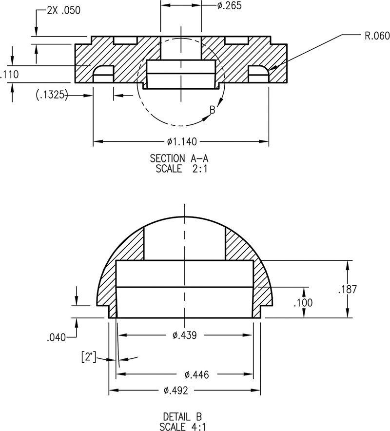
Showing Enlarged Details
Figure 7.24 shows drawing details clearly by including detail views drawn at a larger scale. When adding a detail, draw a circle around the features that will be included in the detail as shown in Figure 7.24 (top). Place the detail view on the sheet as you would a removed view. Label successive details with the word DETAIL followed by a letter, as in DETAIL A, DETAIL B, and so on, and note the scale for the detail below its name.
7.24 Enlarged Detail
Enlarged details are easy to generate using CAD software.
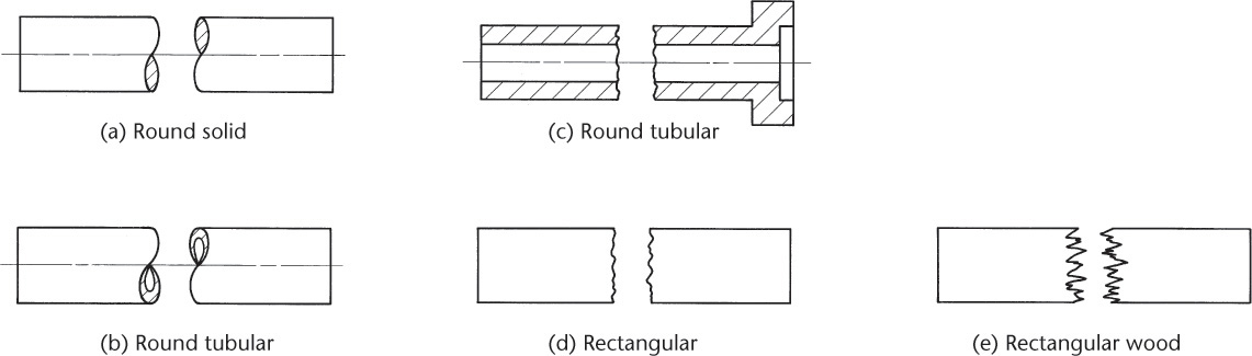
Conventional Breaks
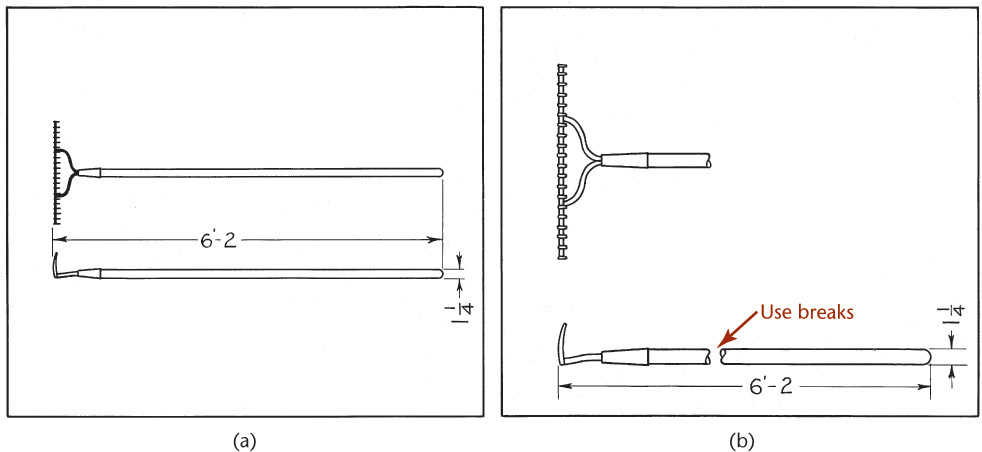
To shorten the view of a long object, you can use break lines as shown in Figure 7.25. Figure 7.26 shows two views of a garden rake. When the long handle of the rake is shown to scale, the details of the drawing are small and hard to read. Using a break to leave out a portion of the handle allows the scale for the ends to be increased to show the details clearly.
7.25 Conventional Break
7.26Conventional breaks allow for increased scale to show detail.
7.10 Alignment of Views
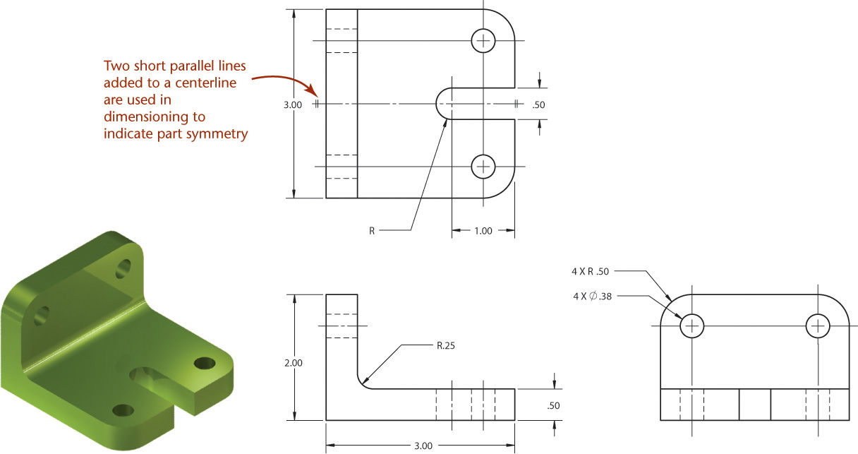
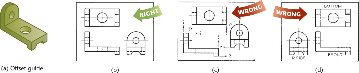
Always draw views in the standard arrangement shown in Figure 7.27 to be sure that your drawings are not misinterpreted. Figure 7.27a shows an offset guide that requires three views. Their correct arrangement is shown in Figure 7.27b. The top view should be directly above the front view, and the right-side view directly to the right of the front view—not out of alignment, as in Figure 7.27c, unless absolutely necessary and then the viewing directions must be clearly labeled in a pictorial view.
7.27 Alignment of Views for Third-Angle Projection
Never draw the views in reversed positions, with the bottom over the front view or the right side to the left of the front view, as shown in Figure 7.27d. Even though the views do line up with the front view, this arrangement could be misread.
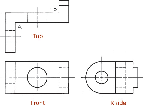
Figure 7.28 shows three views in the correct alignment, but this drawing has a poor choice for the front view. The front view should show the shape of the object clearly. One way to consider this is that the front view shows the most information about the material that would have to be removed from a block.
7.28 Three Views in Correct Alignment but Poor Choice of Front View
After design sketches are completed, you will usually follow them with detailed CAD models and drawings. In CAD drawings, you should apply the same rules for arranging views, clearly depicting the subject of the drawing, using the proper line patterns and lineweights, and following all the necessary standards as used in drawings created by hand.
Tip
Because CAD makes it easy to move whole views, it is tempting to place views where they fit on the screen or plotted sheet and not in the standard or alternative projected arrangement. This is not acceptable, unless you label the viewing direction and show a removed view. Use removed views only when they are really necessary and be sure to label them clearly.
7.11 Removed Views
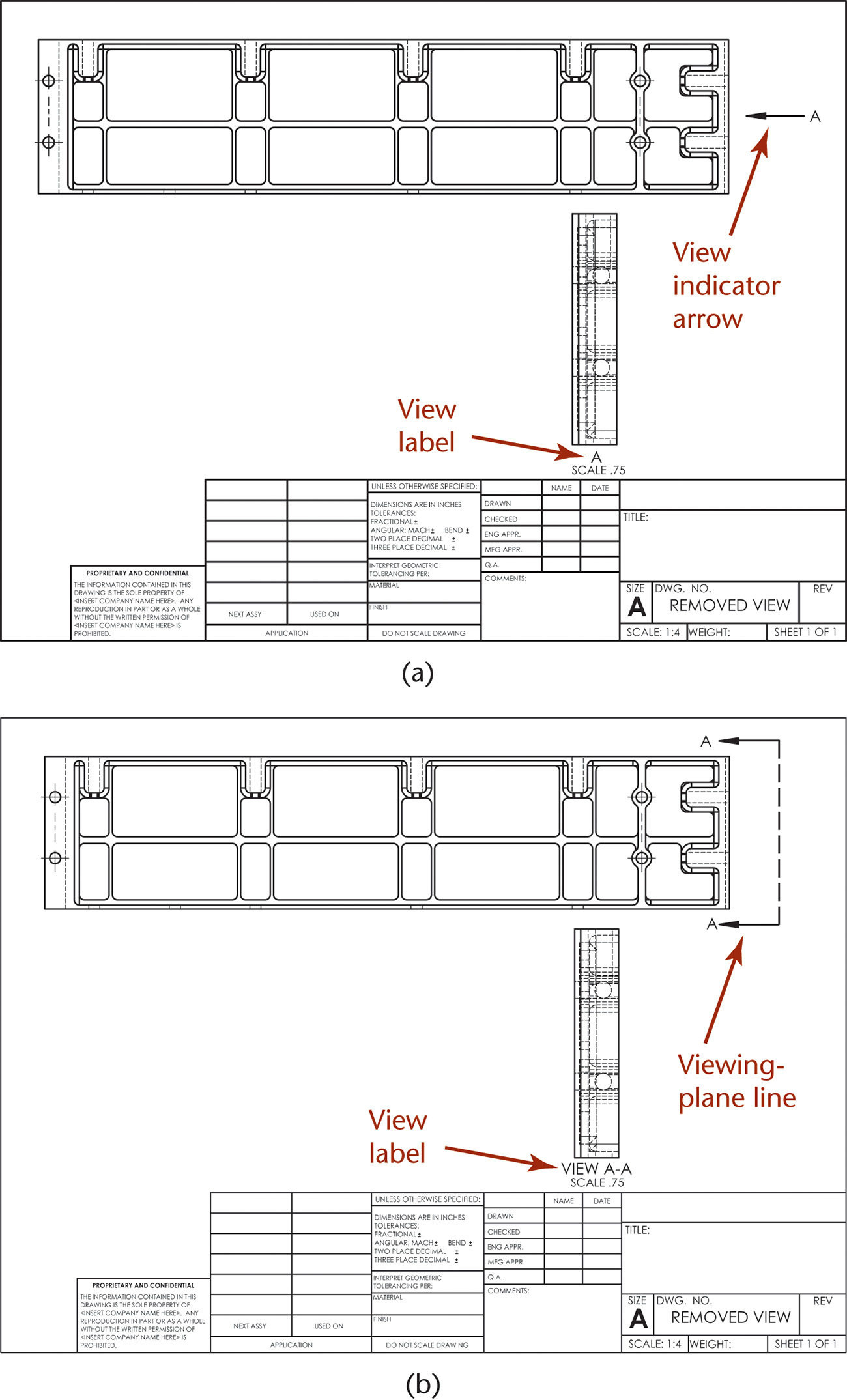
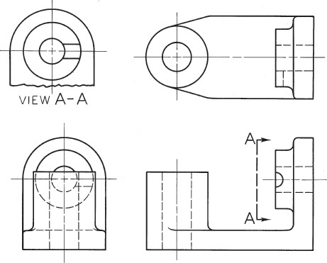
A removed view is a complete or partial view removed to another place on the sheet so that it is no longer in direct projection with any other view, as shown in the upper left corner of Figure 7.29. A removed view may be used to show a feature of the object more clearly, possibly to a larger scale, or to save drawing a complete regular view. A viewing-plane line is used to indicate the part being viewed. The arrows at the corners show the direction of sight. The removed views should be labeled View A–A or View B–B and so on; the letters refer to those placed at the corners of the viewing-plane line. A view indicator arrow can also be used to show the viewing direction for the removed view, as shown in Figure 7.30. Be sure to label the removed view clearly and provide its scale if it is different from the overall drawing scale.
7.29 Removed View Using Viewing-Plane Line
7.30 Removed View Using View Indicator Arrow
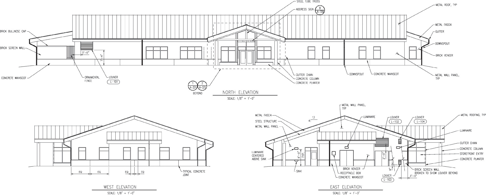
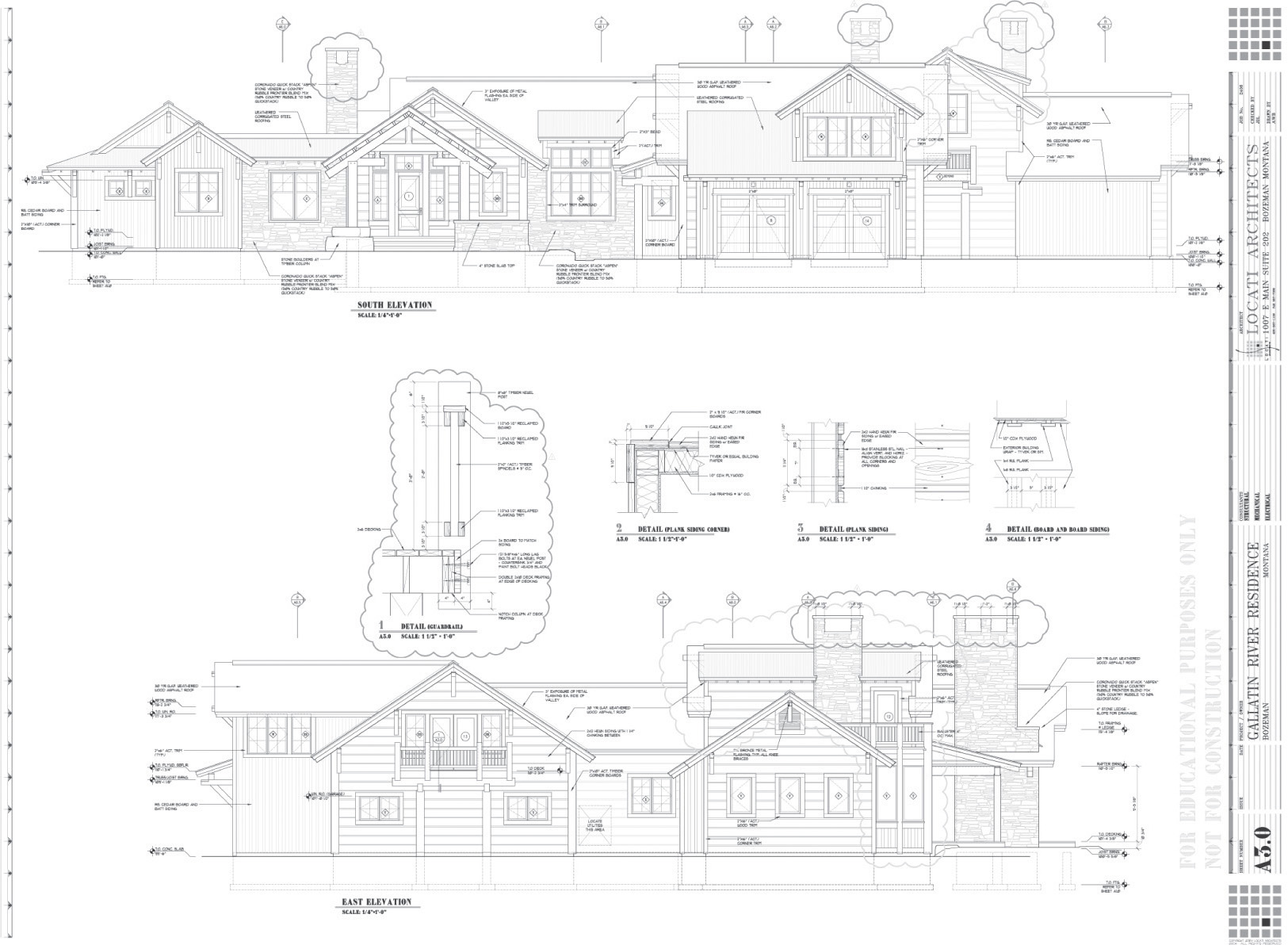
Architectural drawings often cannot fit even two standard views on the sheet. The sheets are typically labeled to indicate the standard views, as in Figure 7.31. Views are labeled, for example, “Plan” for the top view, “East Elevation” for the side view seen from the east compass direction, and so forth. Additional views use a viewing-plane line or arrow to indicate the direction of sight.
7.31 Architectural Drawing with Views Labeled (Courtesy of CH2M HILL.)
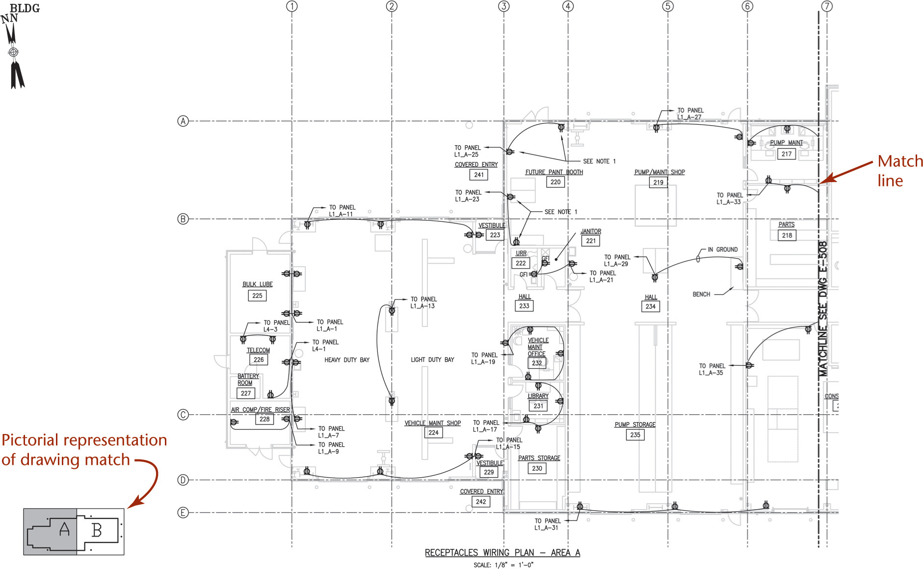
In large civil drawings and other complex drawings such as the electrical drawing in Figure 7.32, one entire view may not be able to be shown clearly on a single sheet. For projects that extend sheet to sheet, match lines are often drawn showing how one sheet matches to the previous one.
7.32 A Portion of a Building System Electrical Drawing Using Match Lines (Courtesy of CH2M HILL.)
7.12 Right-Hand and Left-Hand Parts
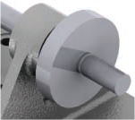
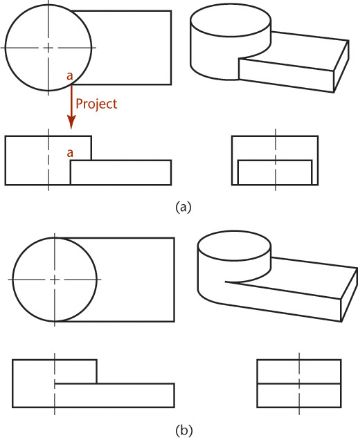
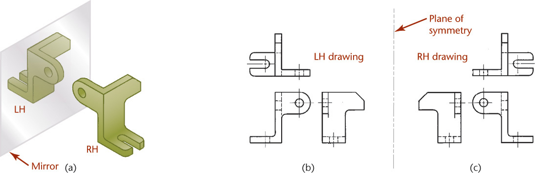
Often, parts function in pairs of similar opposite parts, but opposite parts can rarely be exactly alike. For example, the right-front fender of an automobile cannot be the same shape as the left-front fender. A left-hand part is not simply a right-hand part turned around; the two parts are mirror images and are not interchangeable.
On sketches and drawings a left-hand part is noted as LH, and a right-hand part as RH. In Figure 7.33a, the part in front of the mirror is a right-hand part, and the image shows the left-hand part. No matter how the object is turned, the mirror image will show the left-hand part. Figures 7.33b and c show left-hand and right-hand drawings of the same object.
7.33 Right-Hand and Left-Hand Parts
Ordinarily you draw only one of two opposite parts and label the one that is drawn with a note, such as LH PART SHOWN, RH OPPOSITE. If the opposite-hand shape is not clear, you should make a separate sketch or drawing to show it clearly and completely.
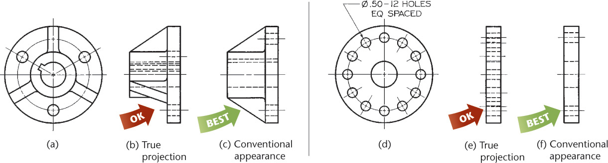
7.13 Revolution Conventions
Regular multiview projections are sometimes awkward, confusing, or actually misleading. For example, Figure 7.34a shows an object that has three triangular ribs, three holes equally spaced in the base, and a keyway. The right-side view is a regular projection, but is not recommended—the lower ribs appear in a foreshortened position, the holes do not appear in their true relation to the rim of the base, and the keyway is projected as a confusion of hidden lines.
7.34 Revolution Conventions
The method shown in Figure 7.34c is preferred because it is simpler to read and requires less time to sketch. Each of the features mentioned has been revolved in the front view to lie along the vertical centerline, from which it is projected to the correct side view.
Figures 7.34d and 7.34e show regular views of a flange with several small holes. The hidden holes are confusing and take unnecessary time to show. Figure 7.34f shows the holes revolved for clarity.
Figure 7.35 shows a regular projection with a confusing foreshortening of its inclined arm. In Figure 7.35b, the lower arm is revolved to line up vertically in the front view so that it projects the true length in the side view and makes the object’s symmetry clear.
7.35 Revolution Conventions
Revolutions like these are frequently used in connection with sectioning. Revolved sectional views are called aligned sections.
In views generated from 3D CAD models, revolving the features to show their true size is not required, but it is preferred, especially in hand-drawn and 2D CAD drawings.
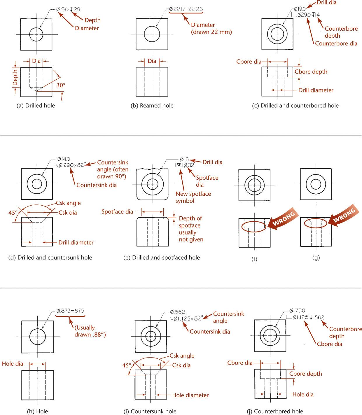
Common Hole Features Shown in Orthographic Views
Orthographic views of common hole features are shown in Figure 7.36. See Table 7.1 on page 286 for descriptions of these common hole features.
7.36 Representing Holes in Orthographic Views; Dimensions for (a)–(e) in Metric, (h)-(j) in Inches
Common Features Shown in Orthographic Views
Orthographic views of common features are shown in Figure 7.37. See Table 7.1 on page 286 for descriptions of common features.
7.37 Representing Common Features in Orthographic Views
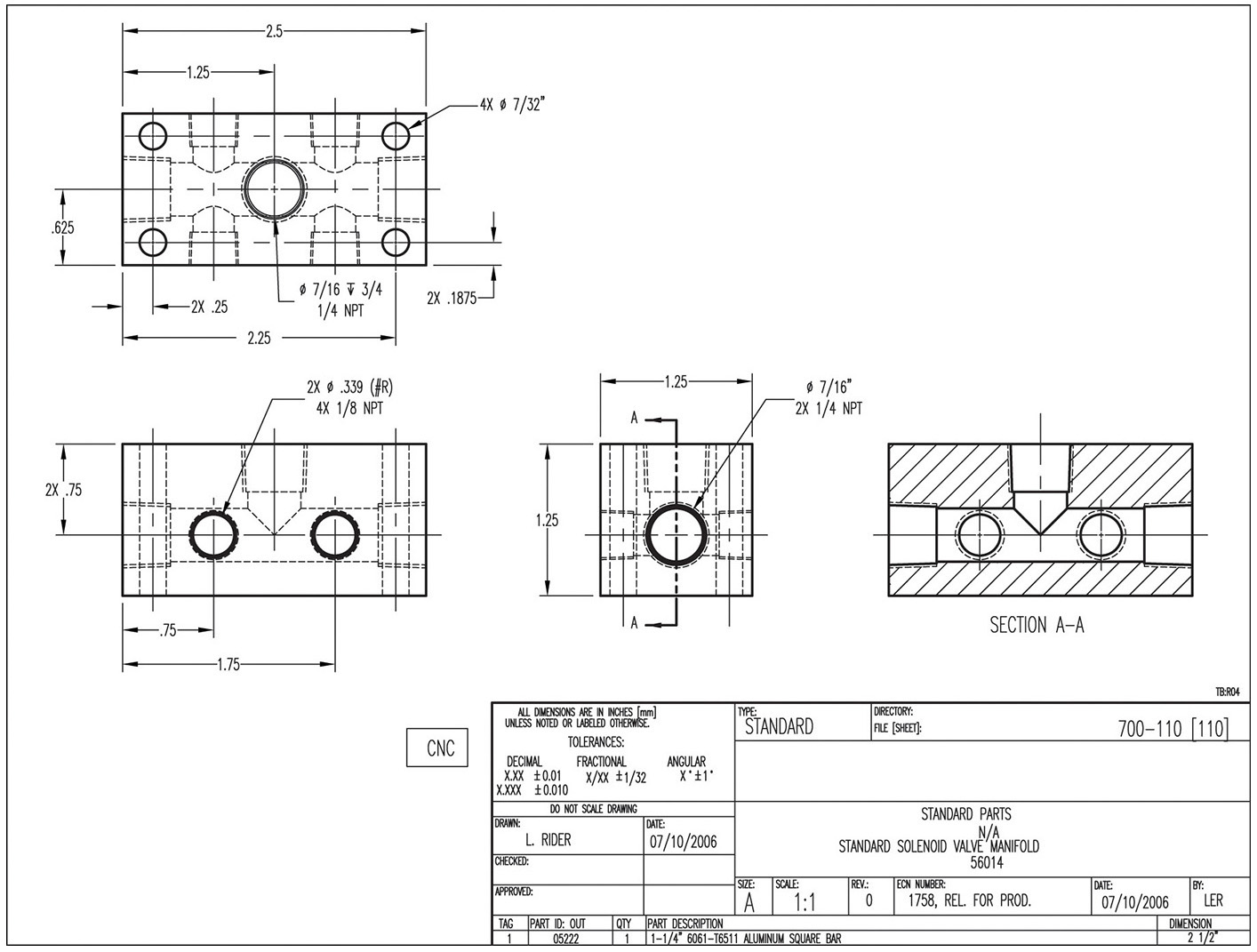
Portfolio
Orthographic Views of a Solenoid Valve Manifold. This drawing is for a part that has many intersecting holes. (Courtesy of Wood’s Power-Grip Co., Inc.)
The views in this architectural drawing are too large to fit on a sheet in typical projection, so removed views are used. Notice that each view is clearly labeled as to its direction of sight, since the views are not in projection. (Courtesy of Locati Architects.)
• Irregular curves can be plotted by identifying points on the object. The points can be projected to approximate the boundaries of the curved surface.
• Drawing conventions define usual practices for the representation of features such as holes, bosses, ribs, webs, lugs, fillets, and rounds.
• Use the same main practices to arrange drawing views on the sheet for both hand-drawn and CAD drawings. Show and label enlarged details and removed views. Use partial views and leave out hidden lines as long as the object is shown clearly.
• When curved and planar surfaces intersect, an edge is formed that is represented by a line in the drawing. When curved and planar surfaces are tangent, no edge is formed, so no line is needed. If the drawing is not clear without it, use a phantom line to show tangencies.
• Common types of holes are through, blind, countersunk, counterbored, and spotfaced.
• Fillets, rounds, and runouts are special types of tangent contours formed on parts with rounded edges.
• When necessary for clarity, features are sometimes shown in a revolved position using revolution conventions.
• Break lines can be used to leave out a section of a part where it is uniform or repetitive. Often, this is done to enlarge the scale of the remaining portions of the part so that details can be seen clearly.
Review Questions
1. If the top view of an object shows a drilled through hole, how many hidden lines will be necessary in the front view to describe the hole? How many if the hole is countersunk? Counterbored?
2. If a plane surface intersects a contoured surface, should you show a line in the drawing to represent that intersection? What about when the plane is tangent?
3. What is a fillet? A round? A lug? A boss? Knurling?
4. How do you show right-hand and left-hand parts?
5. Which is easier, creating an enlarged detail by hand or using a CAD system?
Chapter Exercises
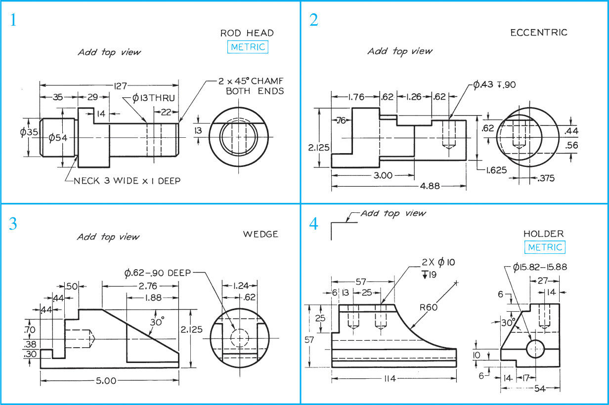
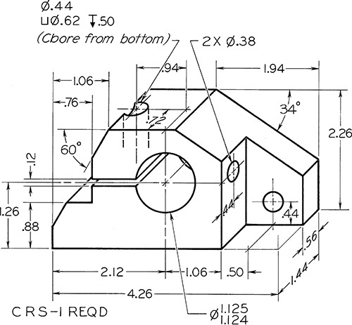
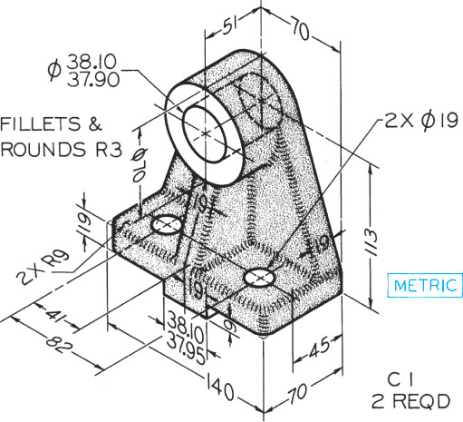
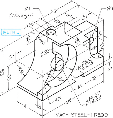
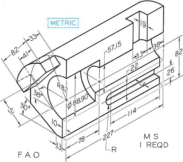
Exercise 7.1 Missing-View Problems. Sketch or draw the given views, and add the missing view. These exercises are designed to fit on 8.5″ × 11″ A-size or A4 metric size paper. Use a title block or title strip as assigned by your instructor. If dimensions are required, study Chapter 11 and use metric or decimal-inch dimensions as assigned by your instructor. Move dimensions to better locations where possible.
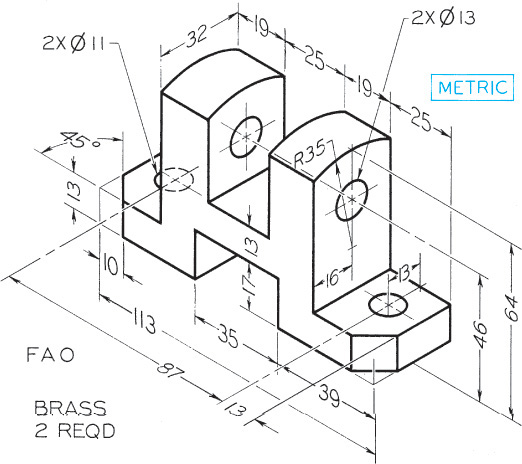
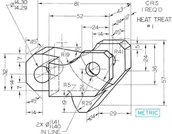
*Sketch or draw necessary views. These exercises are designed to fit on 8.5″ × 11″ A-size or A4 metric size paper. Use a title block or title strip as assigned by your instructor. If dimensions are required, study Chapter 11 and use metric or decimal-inch dimensions as assigned by your instructor. Move dimensions to better locations where possible.
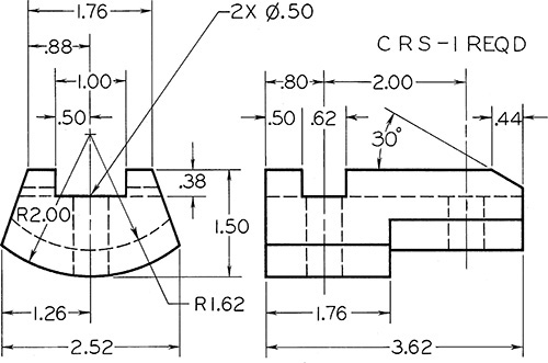
Exercise 7.34 Lead Screw Bracket.** Draw half size.
**Sketch or draw necessary views. Larger and more detailed parts show the details more clearly when drawn on larger sheet sizes. Consider using B, C, or A3 or A2 sheets. Use a title block or title strip as assigned by your instructor. If dimensions are required, study Chapter 11 and use metric or decimal-inch dimensions as assigned by your instructor. Move dimensions to better locations where possible.
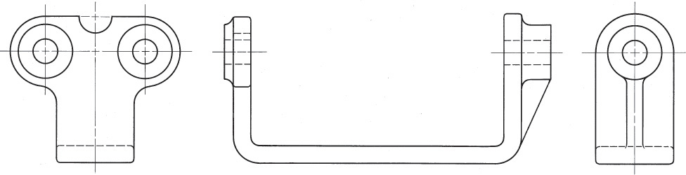
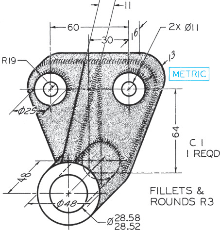
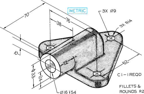
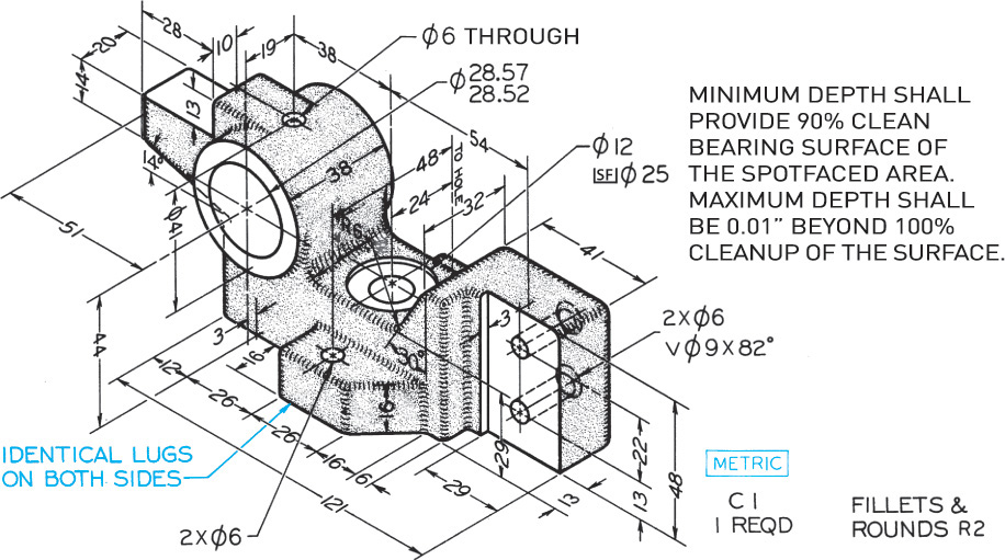
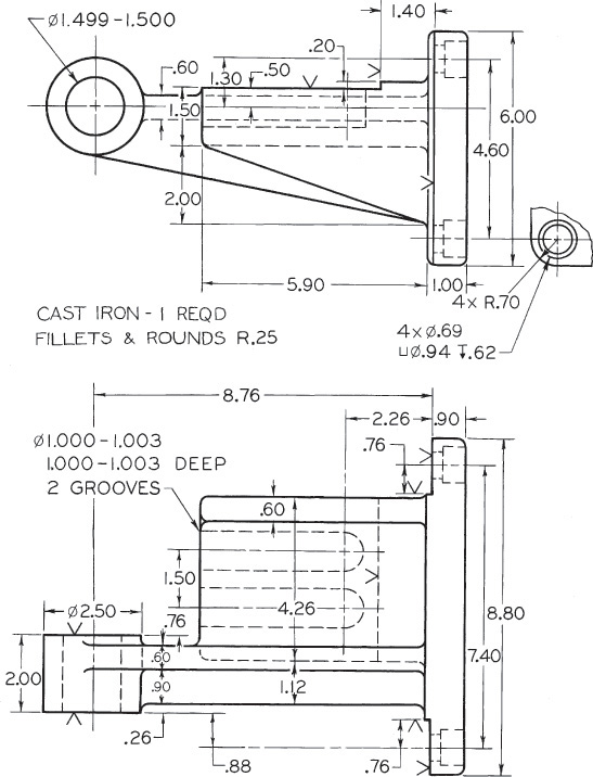
Exercise 7.47 Feed Shaft Bracket. Given: Front and top views. Required: Front, top, and right-side views, half size.*
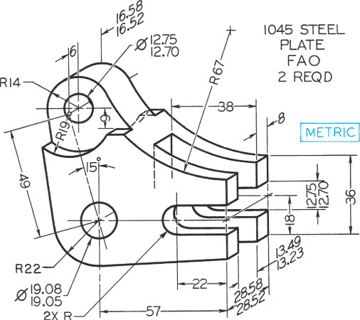
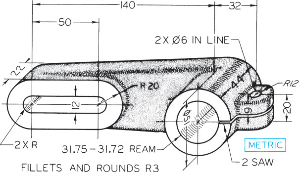
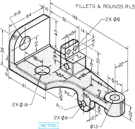
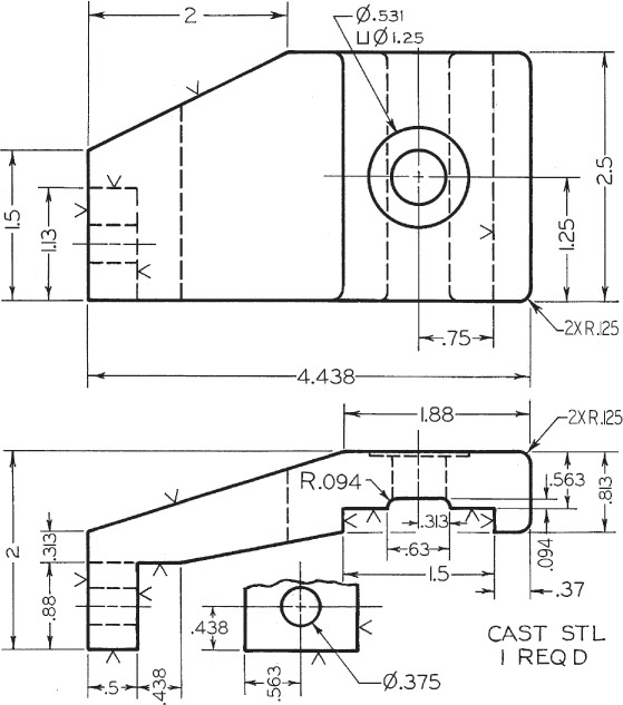
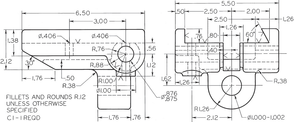
Exercise 7.48 Trip Lever. Given: Front, top, and partial side views. Required: Front, bottom, and left-side views, drawn completely.*
*Sketch or draw necessary views. Larger and more detailed parts show the details more clearly when drawn on larger sheet sizes. Consider using B, C, or A3 or A2 sheets. Use a title block or title strip as assigned by your instructor. If dimensions are required, study Chapter 11 and use metric or decimal-inch dimensions as assigned by your instructor. Move dimensions to better locations where possible.
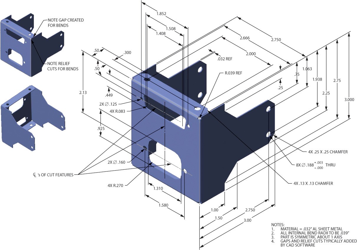
Exercise 7.49 Electronics Enclosure. Create a drawing with the necessary orthographic views for the sheet metal electronics mount.
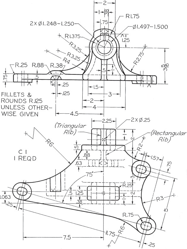
Exercise 7.50 Gyroscope Base. Create a drawing with the necessary orthographic views.
Exercise 7.51 Pry Bar. Create a drawing with the necessary orthographic views for the pry bar.
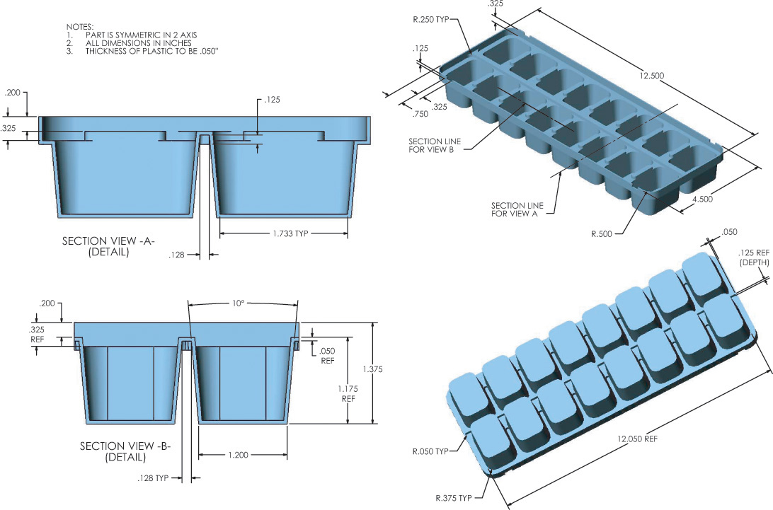
Exercise 7.52 Ice Cube Tray. Create a drawing showing the necessary orthographic views of the ice-cube tray.
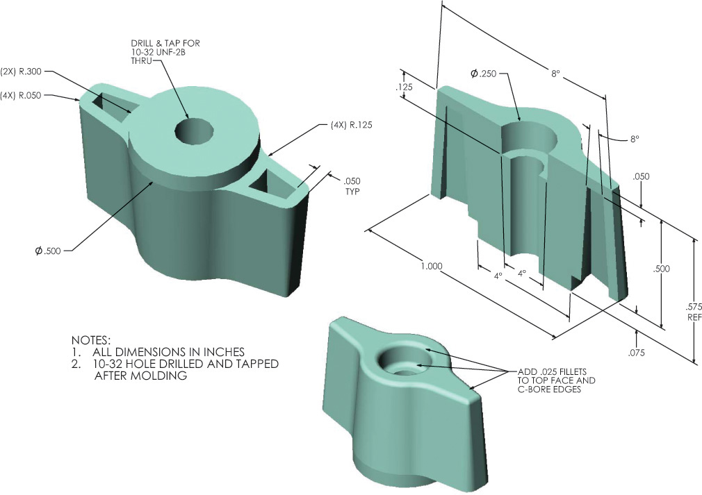
Exercise 7.53 Simple Knob. Create a drawing showing the necessary orthographic views of the knob.
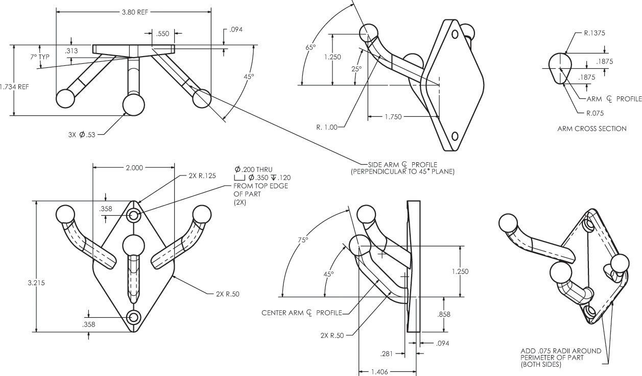
Exercise 7.54 Wall Hanger. Create a drawing showing the necessary orthographic views of the wall hanger. If assigned, create a 3D model and generate the drawing views from the model.
Exercise 7.55Knurl Bracket Bearing. Given: Front and left-side views. Required: Take front as top view on new drawing, and add front and right-side views (Layout B–3 or A3–3).*
*Draw or sketch necessary views. Use metric or decimal-inch dimensions as assigned by the instructor.
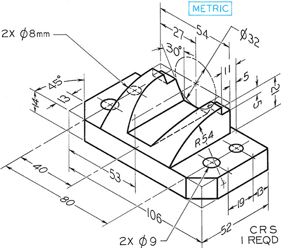
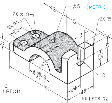
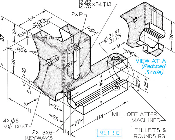
Exercise 7.56 Horizontal Bracket for Broaching Machine. Given: Front and top views. Required: Take top as front view in new drawing; then add top and left-side views (Layout C–4 or A2–4).*
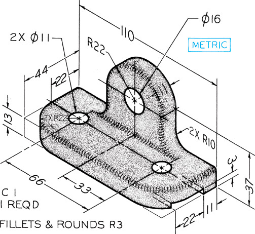
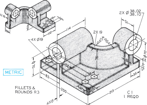
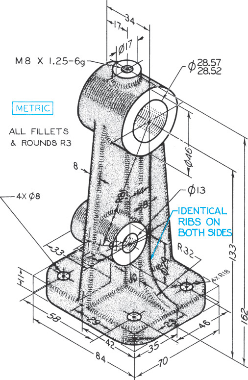
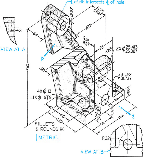
Exercise 7.57 Boom Swing Bearing for a Power Crane. Given: Front and bottom views. Required: Front, top, and left-side views (Layout C–4 or A2–4).*
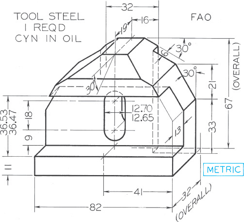
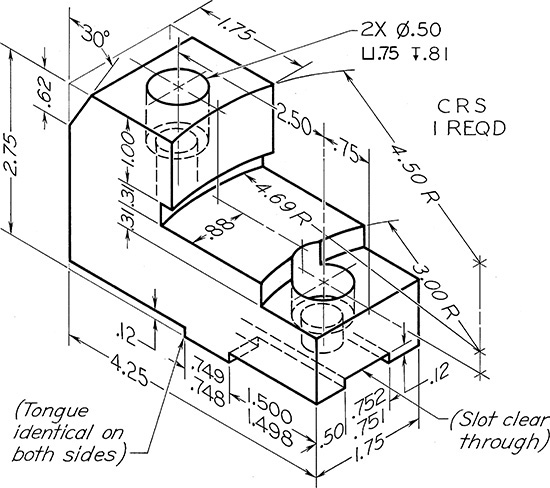
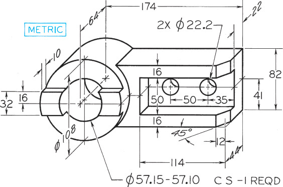
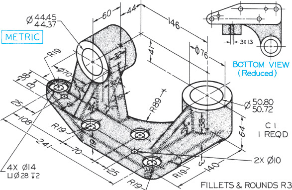
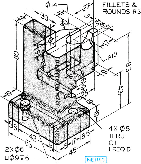
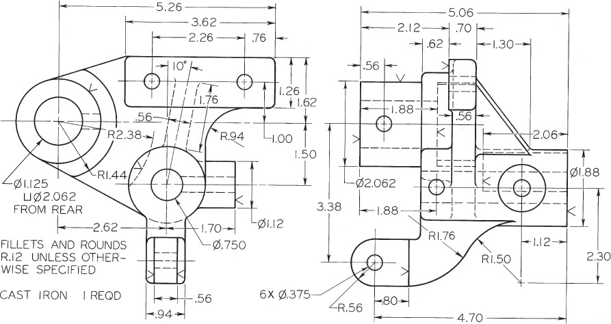
Exercise 7.58 Power Feed Bracket for Universal Grinder. Given: Front and right-side views. Required: Front, top, and left-side views, full size (Layout C–4 or A2–4).*
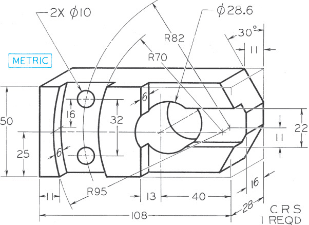
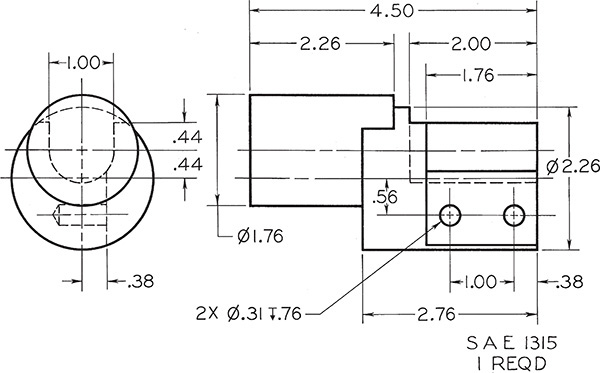
Exercise 7.59 Sliding Nut for Mortiser. Given: Top and right-side views. Required: Front, top, and left-side views, full size (Layout C–4 or A2–4).*
*Draw or sketch necessary views. If dimensions are required, study Chapter 11 and use metric or decimal-inch dimensions as assigned by the instructor.
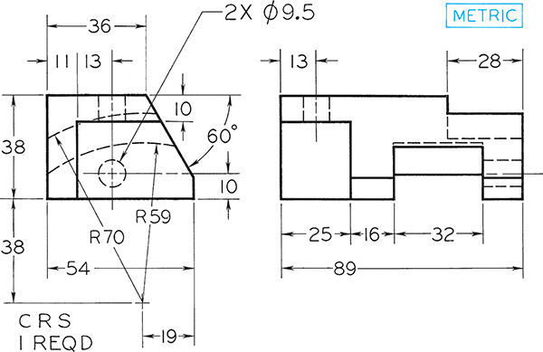
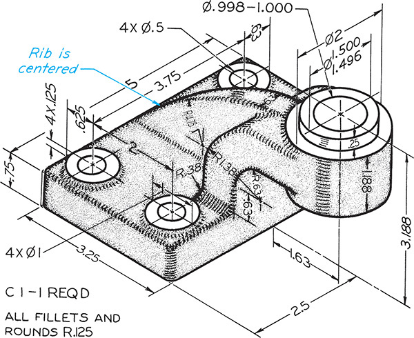
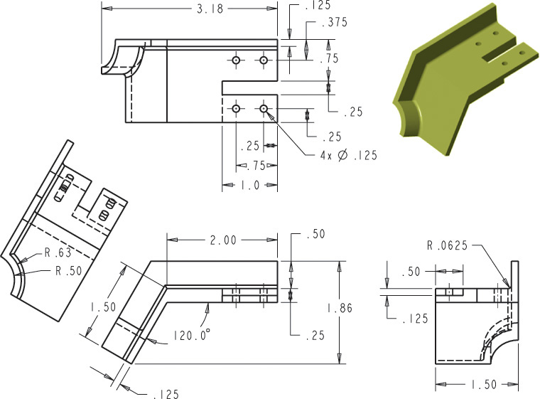
Exercise 7.60 Create a set of orthographic views generated from a solid model for the part shown. Change the overall width of the part from 3.18 to 3.75 inches. Change the angle from 120 to 135 degrees. Keep the remaining dimensions as given.
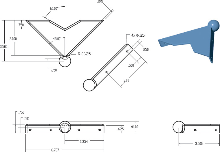
Exercise 7.61 Create a set of orthographic views generated from a solid model for the decorative corner cap part. Change the hole diameters from .125 to .1625. Change the spherical diameter to 1.25.
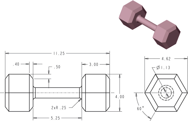
Exercise 7.62 Carefully consider which feature to use as the base feature and how you will create the model for the hand weight so it will update as specified. Determine the weight if this part is cast from ASTM class 20 gray iron. Update the model to create a set of three hand weights of different weights, but maintain the diameter and length of the crossbar grip. Create a set of orthographic views generated from your solid models for each of the three hand weights.
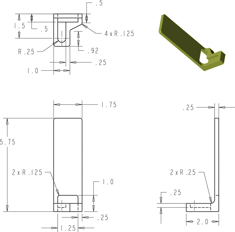
Exercise 7.63 Model the part so that as the overall height, width, depth of the part are changed the other features are updated proportionally to them. Before starting, carefully consider which feature to use as the base feature and how you will create the model so it will be updated as specified. Create a set of orthographic views generated from the solid model for the part as shown. Update the part so the overall height is 6.5″, the overall width is 2.5″ and the depth is 2.25″. Produce a second set of orthographic views showing the updated part.
Exercise 7.64 Create a constraint-based model of the first configuration, save the part, then edit the part to create the second configuration shown. Before starting, carefully consider which feature to use as the base feature and how you will create the model so it will update as specified. Save all part files. Create a set of orthographic views generated from the solid model for each version of the geneva gear.
Exercise 7.65 Create a constraint-based model of the first configuration, save the part, then edit the part to create the second configuration shown. Before starting, carefully consider which feature to use as the base feature and how you will create the model so it will be updated as specified. Save all part files. Create a set of orthographic views for each version of the part.