
Chapter Eight. Section Views
Objectives
After studying the material in this chapter, you should be able to:
1. Understand sections and cutting-plane lines.
2. Apply correct section-lining practices.
3. Recognize and draw section lining for 10 different materials.
4. Draw a section view given a two-view drawing.
5. Demonstrate correct hidden-line practices for section views.
6. Identify seven types of sections.
7. Apply section techniques to create clear, interpretable drawings.
8. Demonstrate the proper techniques for sectioning ribs, webs, and spokes.
9. Use hatching when using conventional breaks to show elongated objects.
10. Interpret drawings that include section views.
Refer to the following standards:
• ANSI/ASME Y14.3 Multiview and Sectional View Drawings
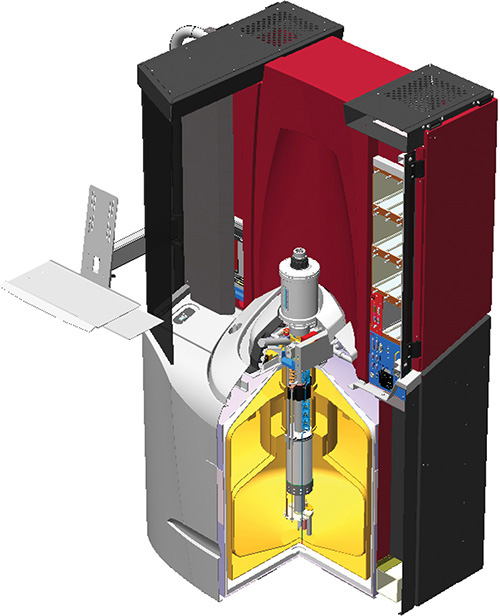
3D Section View of the Superconducting Quantum Interference Device (SQUID). This isometric section view shows the interior details. (Courtesy of Quantum Design.)
Understanding Sections
Section views are used for three main purposes:
• To document the design and manufacture of single parts that are manufactured as one piece.
• To document how multiple parts are to be assembled or built.
• To aid in visualizing the internal workings of a design.
Sections of Single Parts
If you have ever cut a melon in half, you have created a full section in real life (Figure 8.1). To visualize a section of a single part is no different. Think of the part as being sliced through by the cutting plane, as if the plane were a giant cleaver. Once the object is cut, the closer half is pulled away, showing the inside construction of the part.

Full Sections
When the part is cut fully in half, the resulting view is called a full section, as shown in Figure 8.2. Figure 8.3 shows a technical drawing of the part from Figure 8.2 that does not use a section view. Notice how confusing all the hidden lines look. Figure 8.4 shows the same drawing, but this time the right-side view is replaced with a right section view. Now it is much easier to understand.


8.3 Front and Right-Side Views. Parts with a lot of interior detail may have so many hidden lines that their views are confusing.
8.4 Front and Right-Side View in Full Section. Using a section view makes it easier to see interior details.
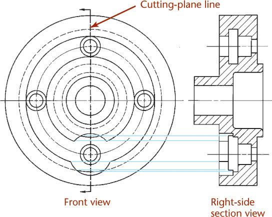
In a drawing with a section view, the missing half is imagined to be removed and is not actually shown removed in any view except the section view. A line called the cutting-plane line provides the information necessary for understanding where the part was cut. The arrows at the ends of the cutting-plane line indicate the direction of sight for the section view.
In the section view, the areas that would have been in actual contact with the cutting plane (refer to the example shown in Figure 8.2) are shown with section lining. Those areas are crosshatched with thin parallel section lines.
The Cutting Plane
The cutting plane is shown in a view adjacent to the section view, in this case the front view. In this view, the cutting plane appears edgewise as a thick dashed line—the cutting-plane line.
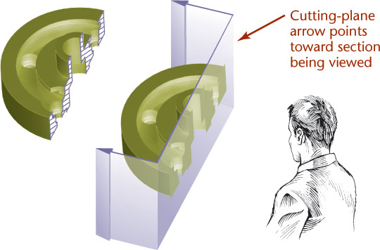
The arrows at the ends of the cutting-plane line indicate the direction of sight for the section view, as shown in Figure 8.4. The arrows point toward the section being viewed as shown in Figures 8.4 and 8.5, not away from it, as in Figure 8.6.

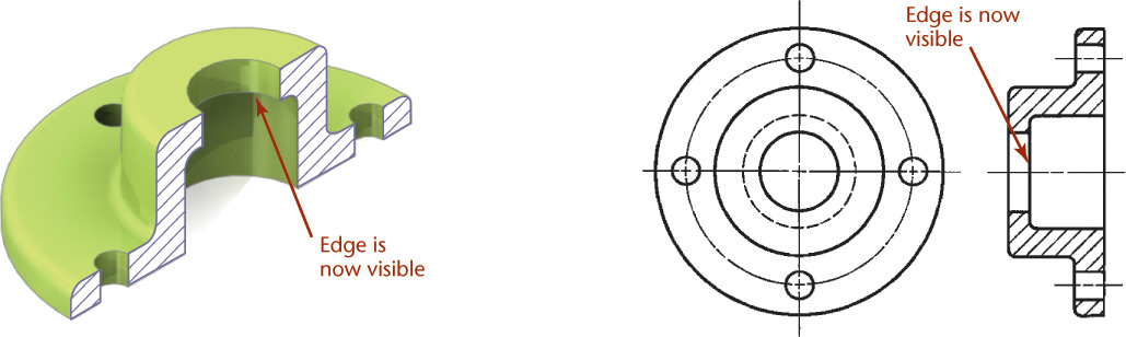
Lines behind the Cutting Plane
The now-exposed visible edges of the object behind the cutting plane are shown, but they are not crosshatched with section lining, because they were not cut. Figure 8.7 shows an example of object edges exposed by the cutting plane appearing as visible lines in the section view. In a full section, the location of the cutting plane is obvious from the section itself, so the cutting-plane line is often omitted. You will learn about other section types that require the cutting-plane line to be understood later in this chapter. Cutting-plane lines should be used wherever necessary for clarity.
Step by Step: Visualizing a Full Section
Choose a Cutting Plane
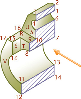
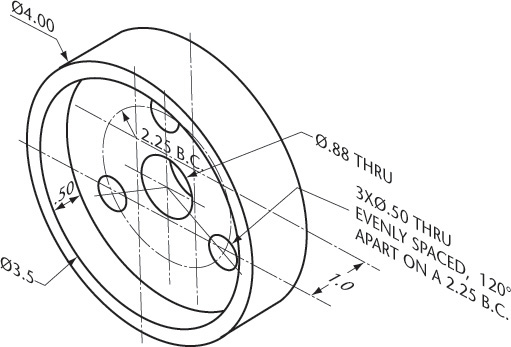
![]() This illustration shows a collar to be sectioned. To produce a clear section showing both the counterbored recess and the smaller hole near the top of the object, choose a cutting plane that will pass through the vertical centerline in the front view, and imagine the right half of the object removed.
This illustration shows a collar to be sectioned. To produce a clear section showing both the counterbored recess and the smaller hole near the top of the object, choose a cutting plane that will pass through the vertical centerline in the front view, and imagine the right half of the object removed.

Identify the Surfaces
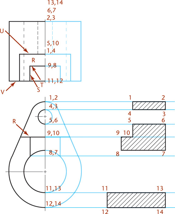
![]() The pictorial drawing of the remaining half is shown at right. The first step in projecting the section view is making sure that you interpret the object correctly. Identifying the surfaces on the object can help.
The pictorial drawing of the remaining half is shown at right. The first step in projecting the section view is making sure that you interpret the object correctly. Identifying the surfaces on the object can help.
Surfaces R, S, T, U, and V have been labeled on the given views and the pictorial view.
Which surface is R in the front view?
Which surface is U in the top view?
Are they normal, inclined, or oblique surfaces?
Can you identify the counterbored recess in each view?
Draw the Section View
![]() To draw the section view, omit the portion of the object in front of the cutting plane. You will be drawing only the portion that remains.
To draw the section view, omit the portion of the object in front of the cutting plane. You will be drawing only the portion that remains.
Determine which are solid parts of the object the cutting plane will pass through. Hint: The outside of an object can never be a hole; it must be solid, unless the cutting plane passes through a slot to the exterior.
The points that will be projected to create the section view have been identified for you in the example shown.
The three surfaces produced by the cutting plane are bounded by points 1-2-3-4 and 5-6-7-8-9-10 and 13-14-12-11. These are shown hatched.
Each sectioned area is completely enclosed by a boundary of visible lines. In addition to the cut surfaces, the section view shows all visible parts behind the cutting plane.
No hidden lines are shown. However, the corresponding section shown in this step is incomplete, because visible lines are missing.
![]() From the direction the section is viewed, the top surface (V) of the object appears in the section as a visible line (12-11-16-15).
From the direction the section is viewed, the top surface (V) of the object appears in the section as a visible line (12-11-16-15).
The bottom surface of the object appears similarly as 14-13-7-6-3-2. The bottom surface of the counterbored recess appears in the section as line 19-20.
Also, the back half of the counterbored recess and the drilled hole appear as rectangles in the section at 19-20-15-16 and 3-4-5-6. These points must also be projected. The finished view is shown at right.
Notice that since all cut surfaces are part of the same object, the hatching must all run in the same direction.

8.1 Placement of Section Views
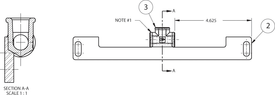
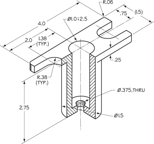
Section views can replace the normal top, front, side, or other standard orthographic views in the standard view arrangement. Figure 8.8 shows an example. In this drawing, the front view of the object is shown in section. Only two views are necessary. The front view is shown as a section view, and the cutting-plane line is shown in the right-side view.
8.8 Section views can replace standard orthographic views. (Courtesy of Wood’s Power-Grip. Co. Inc.)
In Figure 8.9a, the object is cut through with a plane parallel to the front view. The front half of the object is imagined removed. The resulting full section may be referred to as the “front view in section” because it occupies the front view position.

In Figure 8.9b, the cutting plane is a horizontal plane (which would appear as a line in the front view). The upper half of the object is imagined removed. The resulting full section is shown in place of the top view.
When adding a section view to your drawing, keep in mind that your purpose is to document and convey information about your design and show the information in the way that best achieves this objective.
8.2 Labeling Cutting Planes
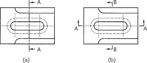
In Figure 8.10, two cutting planes are shown, one a plane parallel to the front view and the other a plane parallel to the side view, both of which appear edgewise in the top view. Each section is completely independent of the other and drawn as if the other were not present.
For section A–A, the front half of the object is imagined removed. The back half is then viewed in the direction of the arrows for a front view, and the resulting section is a front view in section.
For section B–B, the right half of the object is imagined removed. The left half is then viewed in the direction of the arrows for a right-side view, and the resulting section is a right-side view in section. The cutting-plane lines are preferably drawn through an exterior view (in this case the top view, as shown) instead of a section view.
The cutting-plane lines in Figure 8.10 are shown for purposes of illustration only. They are generally omitted in cases where the location of the cutting plane is obvious.
8.3 Line Precedence
When a cutting-plane line coincides with a centerline, the cutting-plane line takes precedence. When the cutting-plane line would obscure important details in the view, just the ends of the line outside the view and the arrows can be shown as in Figure 8.11. When you do this, be sure to leave a small but visible gap between the lines of the view and the small portion of the cutting-plane line.
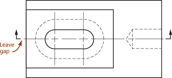
8.11 The cutting-plane line takes precedence over the centerline unless it obscures important detail.
• Show edges and contours that are now visible behind the cutting plane; otherwise a section will appear to be made up of disconnected and unrelated parts. (Occasionally, visible lines behind the cutting plane may be omitted, particularly from those generated from 3D models.)
• Omit hidden lines in section views. Section views are used to show interior detail without a confusion of hidden lines, so add them only if necessary to understand the part.
• Sometimes hidden lines are necessary for clarity and should be used in such cases, especially if their use will make it possible to omit a view (Figure 8.12d).
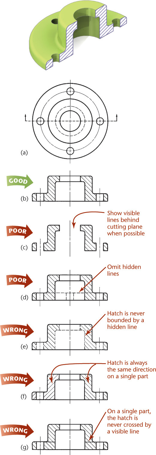
• A sectioned area is always completely bounded by a visible outline—never by a hidden line, because in every case the cut surfaces will be the closest surface in the section view and therefore their boundary lines will be visible (Figure 8.12e).
• In a section view of an object, the section lines in all hatched areas for that object must be parallel, not as shown in Figure 8.12f. The use of section lining in opposite directions is an indication of different parts, as when two or more parts are adjacent in an assembly drawing.
• A visible line can never cross a sectioned area in a view of a single part. This would be impossible on the full section of a single part because the section lines are all in the same plane. A line across it would indicate a change of plane (Figure 8.12g). In an assembly section, this would be possible. You will learn about assemblies later in the chapter.
Tip
Learning the rules for section lining saves time. Extra hidden lines and hatching that is denser than necessary take longer to draw and make drawings slower to print. They also make drawings harder to read.
Tip
In CAD, when views can be placed by projection from a 3D model, saving time by omitting a view is not a big concern, but saving space on the drawing sheet by leaving out a view often may be.
8.5 Cutting-Plane Line Style
Figure 8.13a shows the preferred style of line to use for the cutting-plane line. It is made up of equal dashes, each about 6 mm (1/4″) long ending in arrowheads. This form works especially well for drawings. The alternative style, shown in Figure 8.13b, uses alternating long dashes and pairs of short dashes and ends with arrowheads. This style has been in general use for a long time, so you may still see it on drawings. Both lines are drawn the same thickness as visible lines. The arrowheads at the ends of the cutting-plane line indicate the direction in which the cutaway object is viewed (as was shown in Figure 8.5).

Use capital letters at the ends of the cutting-plane line when necessary to help the drawing’s reader match each cutting-plane line to its section view. Figure 8.10 showed an example where the cutting plane is labeled and the resulting section view is labeled to match. This most often occurs in the case of multiple sections or removed sections, which are discussed later in the chapter.
An alternative method for showing the cutting plane is to draw the cutting-line pattern and then draw reference arrows pointing to it in the direction of sight (Figure 8.14a).
Especially on architectural drawings, the center of the cutting-plane line is often left out and stylized arrows are used to identify the cutting plane (Figure 8.14b).
The arrows on the cutting-plane lines are made larger than the dimension arrowheads to call attention to the location of sections and removed views. Make the arrows 1.4 times the drawing letter height. Make the view label text 1.4 times the drawing letter height also. For example, an 8.5″ × 11″ drawing uses text that is .125″ (1/8″) tall as a minimum, so for this sheet size, use arrows on the cutting plane .175″ (about 3/16″, or about 4.5 mm) tall (Figure 8.13).
Visualizing Cutting-Plane Direction
Correct and incorrect relations between cutting-plane lines and corresponding sectional views are shown in Figure 8.15.

8.6 Section-Lining Technique
The correct method of drawing section lines is shown in Figure 8.16a. When drawing by hand, use a sharp, medium-grade pencil (H or 2H) to draw uniformly thin section lines, or hatching (a term meaning closely spaced parallel lines). There should be a marked contrast between the thin section lines and the thick visible outlines of the part.

Draw section lines at 45° from horizontal unless they would be parallel or perpendicular to major edges of the part, in which case use a different angle. Figure 8.16b shows an example of section lines drawn at a different angle to prevent them from being parallel or perpendicular to visible outlines.
Space the lines as evenly as possible by eye (for most drawings, about 2.5 mm (1/10″) apart). The spacing interval depends on the size of the drawing or of the sectioned area, with larger drawings having wider spacing. In a smaller drawing the spacing interval may be as small as 1.5 mm (1/16″); in a large drawing, it may be 3 mm (1/8″) or more. As a rule, space the lines as generously as possible, yet close enough to clearly distinguish the sectioned areas.
Keep extension lines and dimension values off sectioned areas. If there is no alternative, omit the section lines behind the dimensions (Figure 8.16c).
Tip
Beginners tend to draw section lines too close together. This is tedious and makes small inaccuracies in spacing obvious. After the first few lines, look back repeatedly at the original spacing to avoid gradually increasing or decreasing the intervals between the lines.
Section Lining Large Areas
When adding section lines to a large area, use outline sectioning, where the center portion of the hatched area is left blank to save time and make the view more legible, as shown in Figure 8.17.

Section-Lining Symbols
Section-lining symbols (Figure 8.18) may be used to indicate specific materials. These symbols represent general material types only, such as cast iron, brass, and steel. Because there are so many different types of materials (there are hundreds of types of steel, for example), a general name or symbol is not enough. A detailed specification listing the material must be lettered in the form of a note or in the title strip.

The general-purpose section lining (which is the same as that for cast iron) may be used to represent any material on the detail drawing for a single part.
Using different section-lining patterns helps you distinguish different materials, especially on assembly drawings, but it is acceptable to use the general-purpose symbol shown at different angles for different parts.
Section Lining in CAD
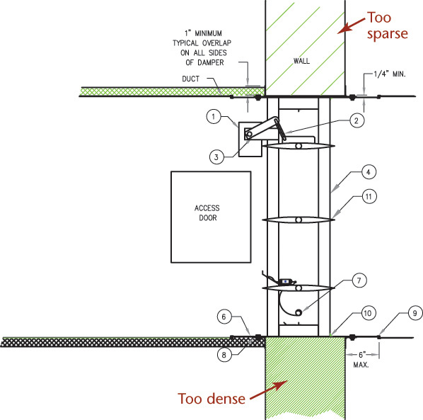
CAD programs usually include libraries that allow you to select from a variety of section-lining patterns, making it easy to use different patterns, angles, and scales for the spacing of the pattern. When using CAD software to hatch an area in the drawing, be careful to specify a scale that relates to the printed drawing scale for that sheet. Otherwise, the hatching may turn out so dense that the object appears to be filled in solid, or so sparse that you do not see any hatching (Figure 8.19).
8.7 Half Sections
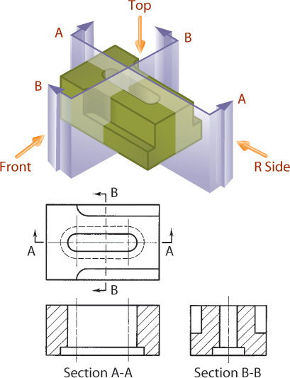
Symmetrical objects can be shown effectively using a special type of section view called a half section (Figure 8.20). A half section exposes the interior of half of the object and the exterior of the other half. This is done by removing one quarter of the object. Half sections are not widely used to create detail drawings showing how to make a single part because it can be difficult to show all the dimensions clearly when some internal features are only partly shown in the sectioned half (Figure 8.20b).
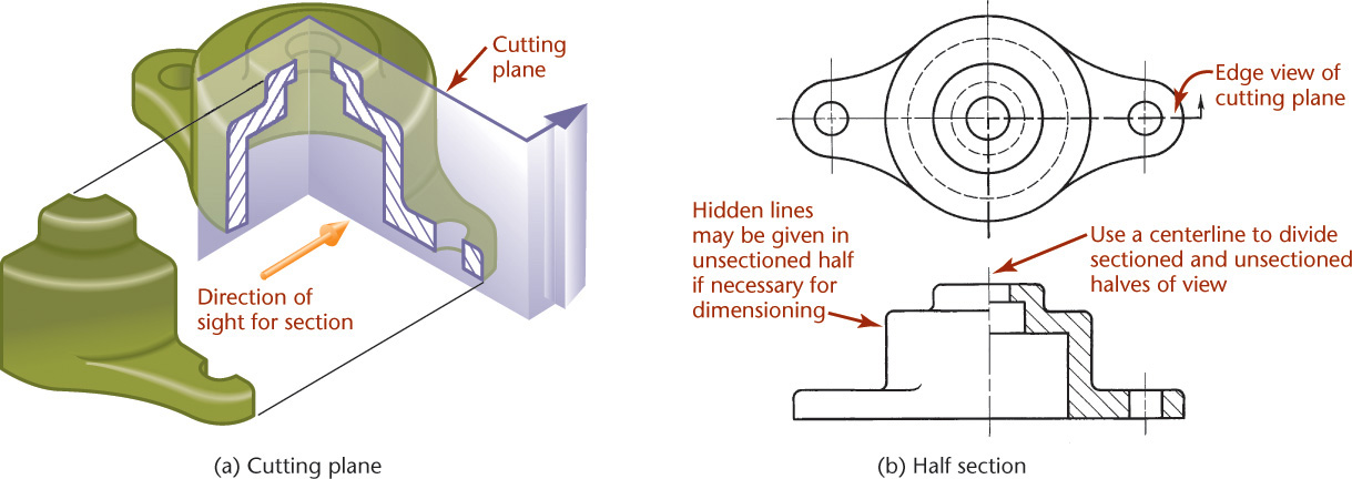
In general,
• Omit hidden lines from both halves of a half section, whenever possible.
• Use a centerline to divide the sectioned half and the unsectioned half, as shown in Figure 8.20b.

Half-section drawings are most useful in showing an assembly where it is often necessary to show both internal and external construction in one drawing view and usually without dimensioning. A broken-out section may be preferred in some cases.
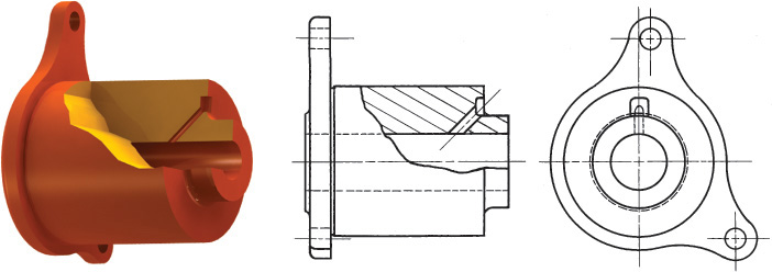
8.8 Broken Out Sections
It often happens that only a partial section of a view is all that is needed to expose interior shapes. Such a section, limited by a break line, is called a broken out section.
In Figure 8.21, a full or half section is not necessary, and a small broken out section is sufficient to explain the construction.
In Figure 8.22, a half section would have caused the removal of half the keyway. The keyway is preserved by breaking out around it. In this case, the section is limited partly by a break line and partly by a centerline in the drawing.
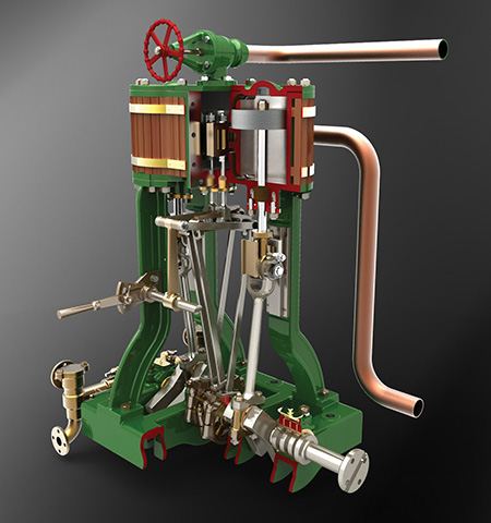
Steam Launch Engine, Modeled Actual Size and Sectioned to Illustrate Assembly and Function. This CAD model was created by William L. Gould from an 1879 “drafting exercise handbook.” (© www.goldstudios.com Used with permission.)
8.9 Revolved Sections
The shape of the cross section of a bar, arm, spoke, or other elongated object can be shown in the longitudinal view by using a revolved section.
To create a revolved section, first imagine a cutting plane perpendicular to the centerline or axis of the object, as shown in Figure 8.23a. Next, revolve the plane 90° about a centerline at right angles to the axis, as shown in Figures 8.23b and c.
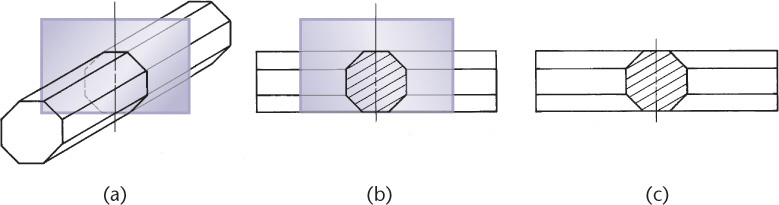
The visible lines adjacent to a revolved section may be broken out if desired, as shown in Figure 8.24.
When you superimpose the revolved section over the top of the view, be sure that any original lines of the view covered by the revolved view are removed (Figure 8.25a).

Show the true shape of the revolved section, regardless of the direction of the lines in the view (Figure 8.25b).
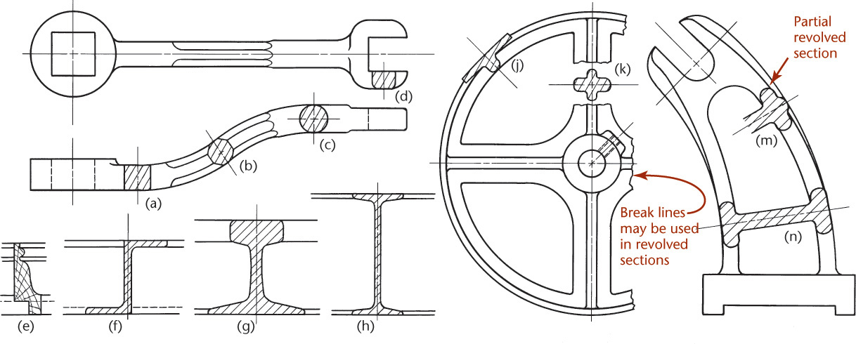
Figure 8.26 shows examples of how revolved sections look in a drawing.
8.10 Removed Sections
A removed section (Figure 8.27) is one that is not in direct projection from the view containing the cutting plane—that is, it is not positioned in agreement with the standard arrangement of views. Be sure to keep the section in its normal orientation and do not turn it a different direction on the sheet. If you must rotate the view, use a rotation arrow as shown in Figure 8.28 and note the angle the view was rotated.

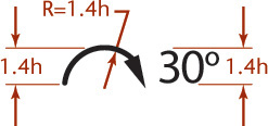
8.28 Rotation Arrow Symbol. Use this to label a view that has been rotated (h = letter height in the drawing).
Removed sections should be labeled, such as section A–A and section B–B, corresponding to the letters at the ends of the cutting-plane line (Figure 8.27). They should be arranged in alphabetical order from left to right on the sheet. Section letters should be used in alphabetical order, but letters I, O, and Q should not be used because they are easily confused with the numeral 1 or zero. Figure 8.29 shows several removed sections.

A removed section is often a partial section, in which only a portion of the section view is drawn. Removed sections are frequently drawn to an enlarged scale (Figure 8.29) to show detail and provide space for dimensions. When using an enlarged scale be sure to indicate the scale below the section view’s title, as in Figure 8.27.
A removed section should be placed so that it no longer lines up in projection with any other view. It should be separated clearly from the standard arrangement of views (see Figure 8.30). Whenever possible, removed sections should be on the same sheet as the regular views. If a section must be placed on a different sheet, cross-references should be given on the related sheets. A note should be given below the section title, such as
SECTION B-B ON SHEET 4, ZONE A3
A similar note should be placed on the sheet on which the cutting-plane line is shown, with a leader pointing to the cutting-plane line and referring to the sheet on which the section will be found. Sometimes it is convenient to place removed sections on centerlines extended from the section cuts (Figure 8.31).

8.11 Offset Sections
In sectioning complex objects, it is often desirable to show features that do not lie in a straight line by “offsetting” or bending the cutting plane. These are called offset sections.
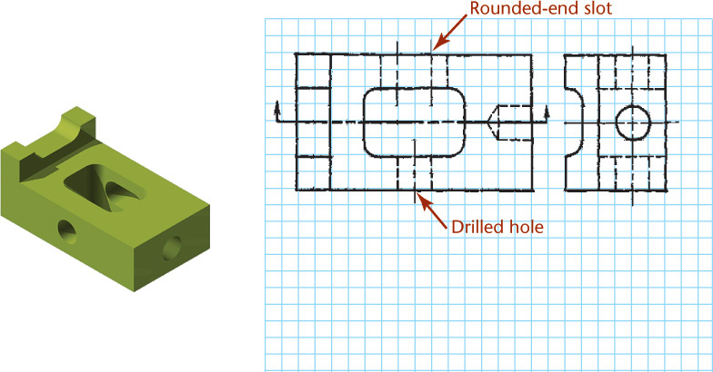
In Figure 8.32a the cutting plane is offset in several places to include the hole at the left end, one of the parallel slots, the rectangular recess, and one of the holes at the right end. The front portion of the object is then imagined to be removed (Figure 8.32b). The path of the cutting plane is shown by the cutting-plane line in the top view (Figure 8.32c), and the resulting offset section is shown in the front view.
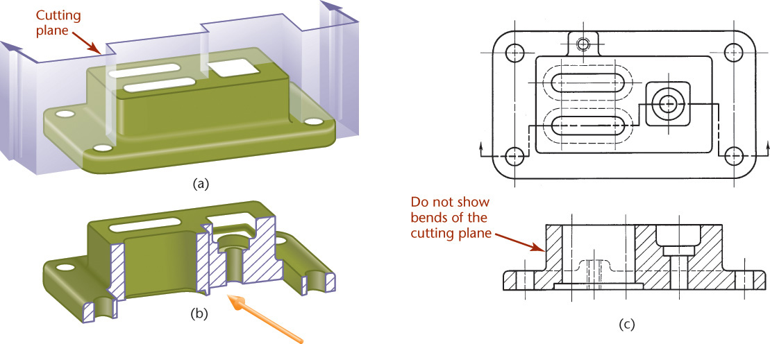
• The offsets or bends in the cutting plane are all 90°.
• The bends in the cutting plane are never shown in the section view.
Figure 8.32 also illustrates how hidden lines in a section eliminate the need for an additional view. In this case, an extra view would be needed to show the small boss on the back if hidden lines were not shown.
Figure 8.33 shows an example of multiple offset sections. Notice that the visible background shapes appear in each section view without the use of hidden lines. It is also acceptable to show only the cut portion, but the views are easier to interpret when the lines that are visible behind the cutting plane are shown.

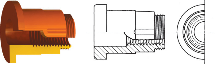
8.12 Ribs in Section
To avoid giving a false impression of thickness and solidity, ribs, webs, gear teeth, and other similar flat features are not hatched with section lining even though the cutting plane slices them. For example, in Figure 8.34, the cutting plane A–A slices through the center of the vertical web, or rib, and the web is not sectioned (Figure 8.34b). Thin features are not hatched even though the cutting plane passes lengthwise through them. The incorrect section is shown in Figure 8.34c. Note the false impression of thickness or solidity resulting from section-lining the rib.

If the cutting plane passes crosswise through a rib or any thin member, as in section B–B, section-line the feature in the usual manner, as in the top view of Figure 8.34a.
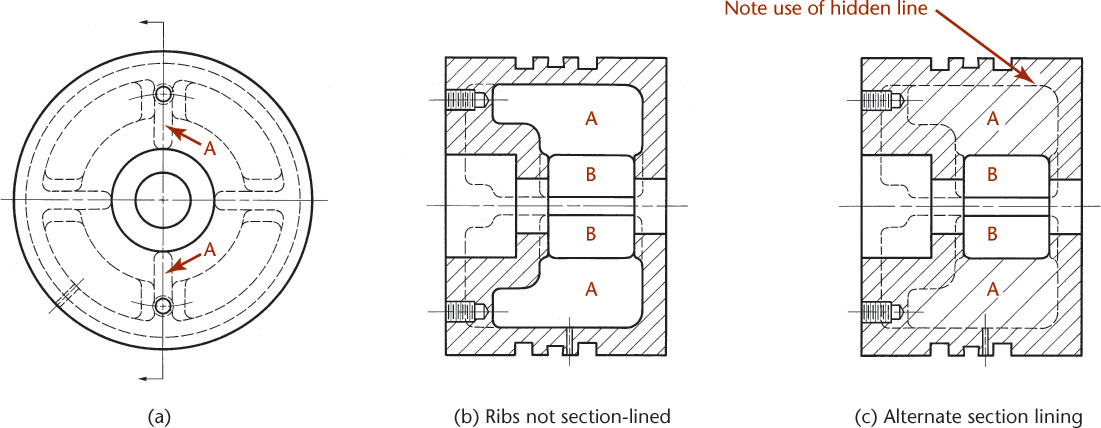
If a rib is not sectioned when the cutting plane passes through it flatwise, it is sometimes difficult to tell whether the rib is actually present, as, for example, ribs A in Figure 8.35a and b. It is difficult to distinguish spaces B as open spaces and spaces A as ribs. In such cases, double-spaced section lining of the ribs should be used (Figure 8.35c). This consists simply of continuing alternate section lines through the ribbed areas, as shown.
8.13 Aligned Sections
When parts with angled elements are sectioned, the cutting plane may be bent to pass through those features. The plane and features are then imagined to be revolved into the original plane. For example, Figure 8.36 shows an aligned section. The cutting plane was bent to pass through the angled arm and then revolved to a vertical position (aligned), from where it was projected across to the section view.
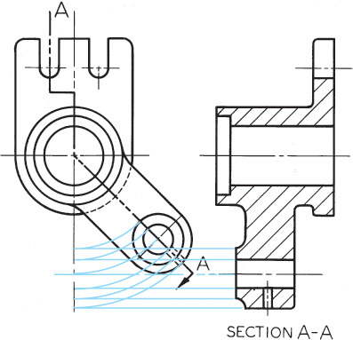
The angle of revolution should always be less than 90° for an aligned section.
Do not revolve features when the clarity of your drawing is not improved. In the exercises later in the chapter, you will see examples of when revolution should not be used.
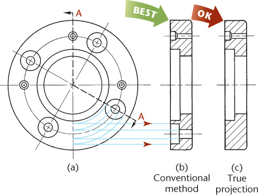
In Figure 8.37 the cutting plane is bent to include one of the drilled and counterbored holes in the section view. The correct section view in Figure 8.37b gives a clearer and more complete description than does the section in Figure 8.37c, which is shown without any bend in the cutting plane.
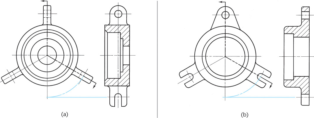
In Figure 8.38a, the projecting lugs are not section-lined for the same reason that the ribs are not sectioned. In Figure 8.38b, the projecting lugs are located so that the cutting plane passes through them crosswise; therefore, they are section-lined.
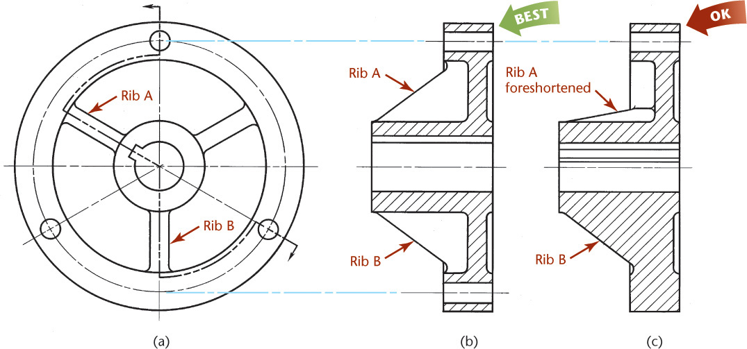
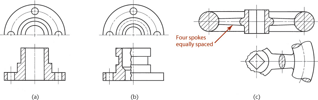
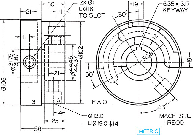
Another example involving rib sectioning and aligned sectioning is shown in Figure 8.39. In the circular view, the cutting plane is offset in circular-arc bends to include the upper hole and upper rib, the keyway and center hole, the lower rib, and one of the lower holes. These features are imagined to be revolved until they line up vertically and are then projected from that position to obtain the section shown in Figure 8.39b. Note that the ribs are not section-lined. If a regular full section of the object were drawn without using the conventions discussed here, the resulting section (Figure 8.39c) would be incomplete and confusing and would take more time to draw. Showing the actual section is acceptable when it is generated from a 3D model. When doing so, take care to provide clear views that can be interpreted by the reader.
In sectioning a pulley or any spoked wheel (Figure 8.40a), it is standard practice to revolve the spokes if necessary (if there are an odd number) and not to section-line the spokes (Figure 8.40b). If the spoke is hatched, the section gives a false impression of continuous metal (Figure 8.40c). If the lower spoke is not revolved, it will be foreshortened in the sectional view, in which it presents an “amputated” and a misleading appearance.
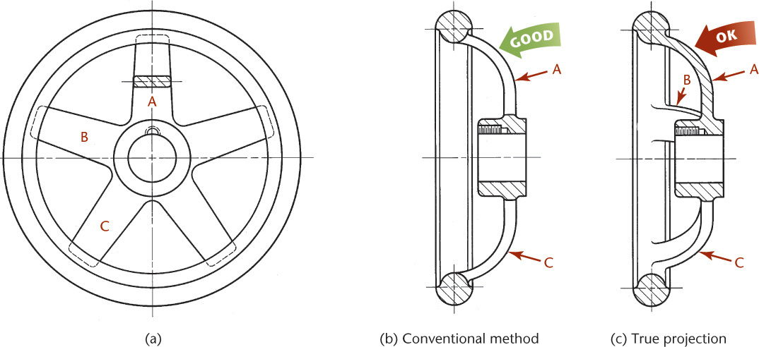
Figure 8.40 also illustrates correct practice in omitting visible lines in a sectional view. Notice that spoke B is omitted in Figure 8.40b. If it is included, as shown in Figure 8.40c, the spoke is foreshortened, difficult and time-consuming to draw, and confusing to the reader of the drawing.
8.14 Partial Views
If space is limited on the paper or to save time, partial views may be used with sectioning (Figure 8.41). Half views are shown in Figures 8.41a and b in connection with a full section and a half section, respectively. In each case the back half of the object in the circular view is shown, to remove the front portion of the object and expose the back portion in the section.
Another method of drawing a partial view is to break out much of the circular view, retaining only those features that are needed for minimum representation (Figure 8.41c).
8.15 Intersections in Sections
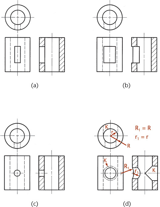
Whenever an intersection is small or unimportant in a section, it is standard practice to disregard the true projection of the figure of intersection, as shown in Figures 8.42a and c. Larger intersections may be projected, as shown in Figure 8.42b, or approximated by circular arcs, as shown for the smaller hole in Figure 8.42d. Note that the larger hole K is the same diameter as the vertical hole. In such cases the curves of intersection (ellipses) appear as straight lines, as shown.
8.16 Conventional Breaks and Sections
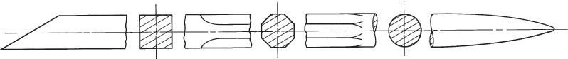
Cross-hatching is often added when showing a conventional break. Conventional breaks are used to shorten the view of an object that is too long to show clearly at one scale on the drawing sheet. Figure 8.43 shows examples of hatching on conventional breaks. The parts to be broken must have the same section throughout, or if they are tapered, they must have a uniform taper.
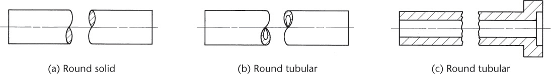
The breaks used on cylindrical shafts or tubes are often referred to as “S-breaks” and are usually drawn by eye, although S-break templates are available.
8.17 Assembly Sections
Section views are often used to create assembly drawings. Figure 8.44 shows an orthographic drawing for an assembly. Notice that the hatching on different parts varies; it has a different hatch pattern or is hatched at a different angle. On the same part, the hatching is always at the same angle to help you recognize the parts easily. Solid features that do not have interior structure are not hatched. You will learn more about these types of drawing in Chapter 14.
CAD at Work: Computer Techniques for Sections
2D and 3D sectional views can be created using CAD. Most CAD systems have a “hatch” command to generate the section lining and hatch patterns to fill an area automatically. A wide variety of hatch patterns are generally available to show materials such as steel, bronze, sand, concrete, and many more.
Creating a full-section view from a 3D model is generally very easy. You often need to define only the cutting plane, viewing direction, scale, and where to place the view on the sheet. Often, the hatching for the cut surfaces is generated automatically. Sectioned views other than full sections can be more difficult to create. When you create an angled cutting plane line for a section view, Autodesk Inventor automatically generates the aligned section. Use this feature only when appropriate, such to show the internal structure of an angled feature. To create good section drawings, you should have a clear understanding of the standards for showing section views.
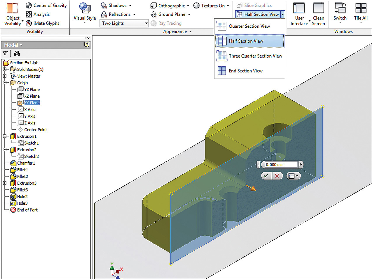
A Section Created in the 3D Model Using Autodesk Inventor (Autodesk screen shots reprinted courtesy of Autodesk, Inc.)

Sections can quickly be added to orthographic drawings generated from a 3D model.
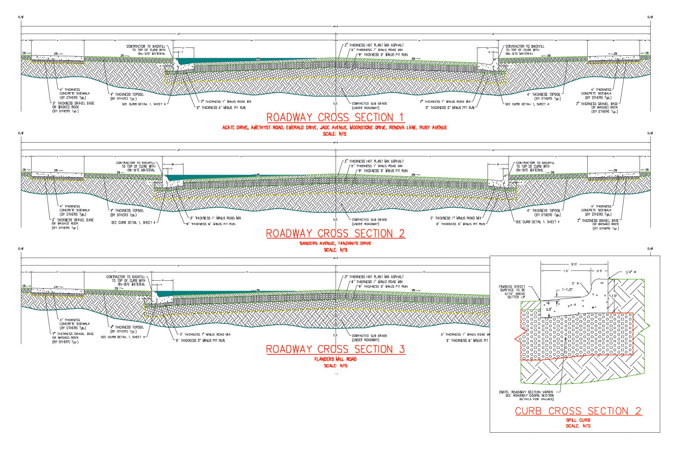
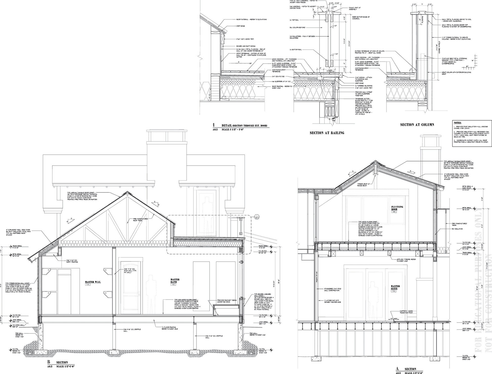
Roadway Sections (Excerpted from a larger drawing). (Courtesy of Locati Architects.)
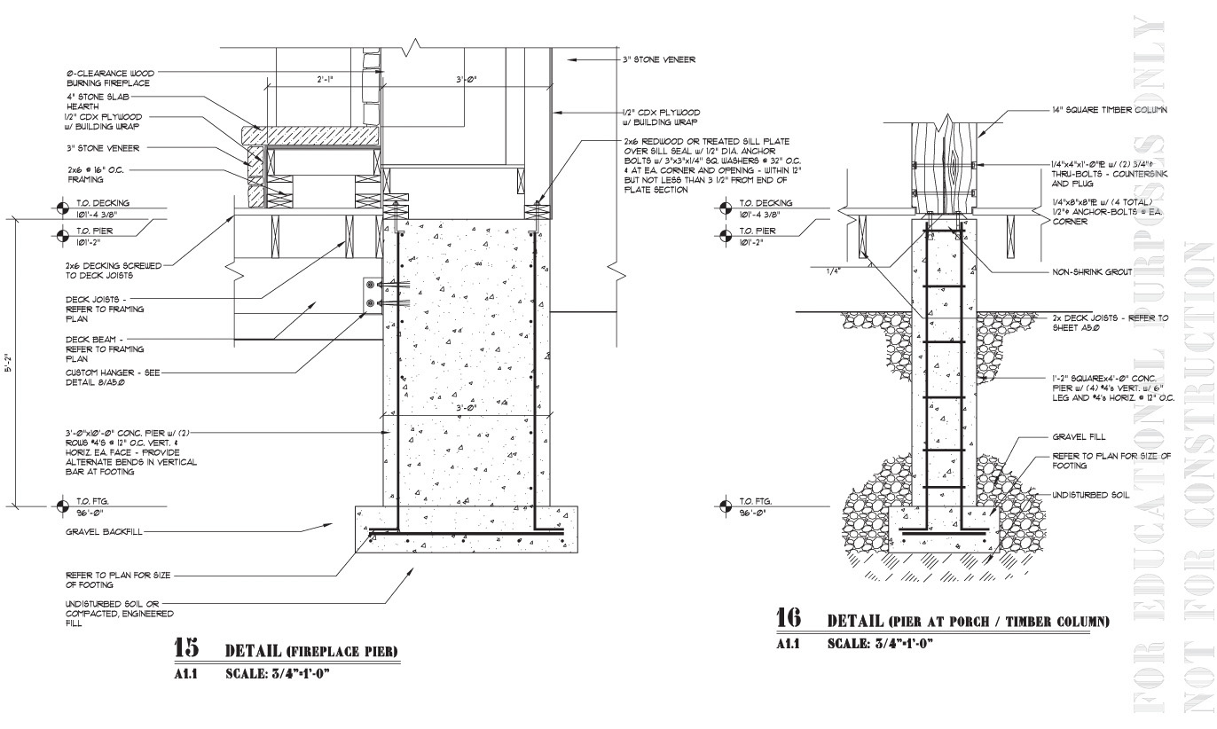
Section Detail (Excerpted from a larger drawing). (Courtesy of Locati Architects.)

Detail Drawing for an Injection Molded Plastic Part with Removed Section Views (Courtesy of Dynojet Research, Inc.)
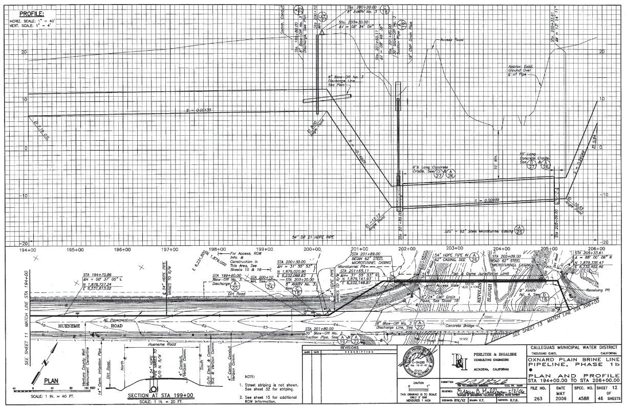
Plan and Profile Drawing with Sections (Courtesy of Perliter & Ingalsbe Consulting Engineers.)
Chapter Summary
Now that you have finished this chapter, you should be able to:
• Show internal details of objects without the need for hidden lines by using section views.
• Imagine a variety of objects cut apart along a cutting-plane line.
• Show section lining (hatching) to indicate the solid parts of the object that would be cut by the cutting plane.
• Check that you are not showing hidden lines where they are no longer needed because the internal surfaces are exposed when the object is imagined cut.
• Use section-lining symbols to indicate the material of the object.
• Leave the section lining off ribs, webs, and spokes that are sectioned lengthwise.
• Revolve symmetrical features so the section view depicts the part’s symmetry.
• Use conventional breaks on drawings to show object details when they would appear too small at a scale where the entire object would be shown on the sheet.
• Interpret assembly drawings that include section views.
Review Questions
1. What does the cutting-plane line represent?
2. Sketch the section line symbols for 10 different materials.
3. List seven different types of sections and sketch an example of each.
4. Which section views are used to replace an existing primary view? Which section views are used in addition to the primary views?
5. How much of an object is imagined to be cut away in a half section?
6. What type of line is used to show the boundary of a broken out section?
7. Why are hidden lines generally omitted in a section view?
8. Why are some symmetrical features, like spokes and webs, revolved in the sectional view?
9. Why is a rib outlined with object lines and not filled with section lining?
Chapter Exercises
Any of the following exercises may be drawn freehand or with CAD. Study Chapter 11 on dimensioning first if you are going to add dimensions to your drawings. Show cutting-plane lines for practice.
Freehand Sectioning Problems
Exercises 8.1–8.4 are especially suited for sketching on 8.5″ × 11″ graph paper with appropriate grid squares. Sketch one or two problems per sheet, adding section views as indicated. To make your drawings fit on the paper easily, use each grid square as equal to either 6 mm or 1/4″.
Exercise 8.1 Redraw the given views and add the front section view.

Exercise 8.2 Redraw the top view, rotate the side view, and move it into a position so that you can project the front view in section. Add the front section view.

Exercise 8.3 Redraw the top view, rotate the side view, and move it into a position so that you can project the front view in section. Add the front section view.

Exercise 8.4 Freehand Sectioning Problems. Sketch views and add sections as indicated by the cutting-plane lines. Cutting-plane lines can be omitted except for parts b and c. (Note: In freehand sketching, revolution conventions for aligned sections are generally observed. See Figure 8.39, Symmetry of Ribs, for an example.)
Exercise 8.5 Bearing. Draw necessary views, with full section.*

Exercise 8.6 Truck Wheel. Draw necessary views, with full section.*

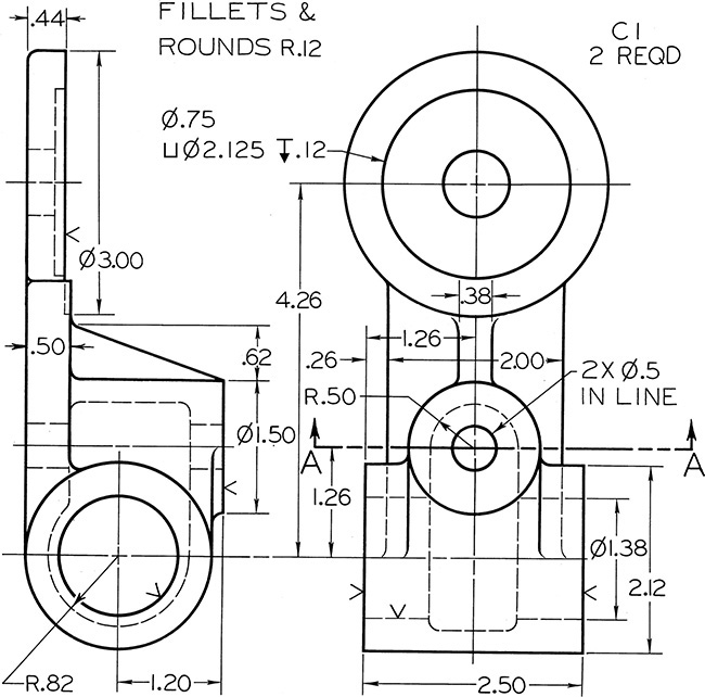
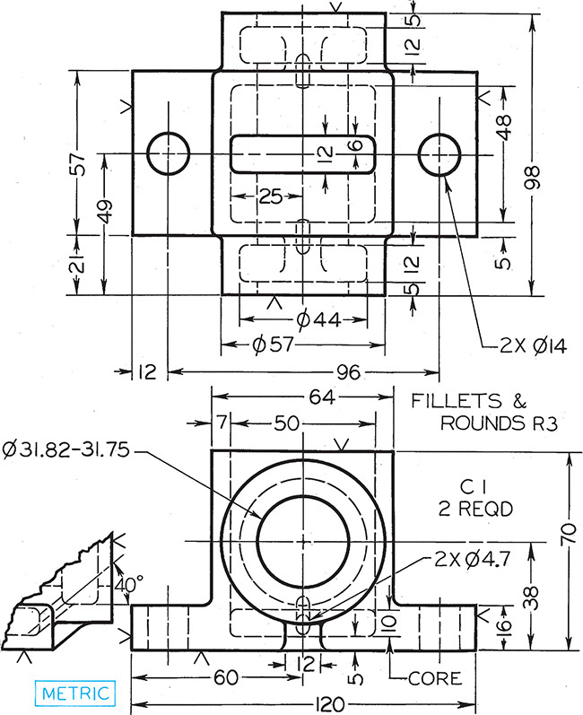
Exercise 8.7 Column Support. Draw necessary views, with broken out section.*
Exercise 8.8 Centering Bushing. Draw necessary views, with full section.*
Exercise 8.9 Special Bearing. Draw necessary views, with full section.*
Exercise 8.10 Idler Pulley. Draw necessary views, with full section.*
Exercise 8.11 Cup Washer. Draw necessary views, with full section.*

Exercise 8.12 Fixed Bearing Cup. Draw necessary views, with full section.*

Exercise 8.13 Stock Guide. Draw necessary views, with half section.*

Exercise 8.14 Bearing. Draw necessary views, with half section. Scale: half size.*

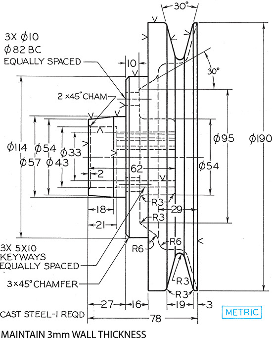
Exercise 8.15 Pulley. Draw necessary views, with full section, and revolved section of spoke.*
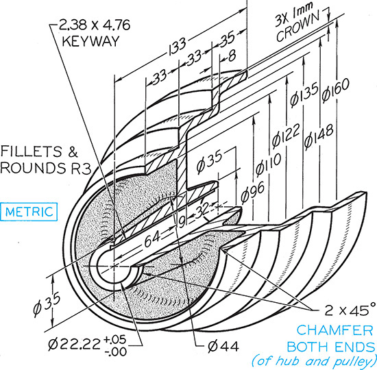
Exercise 8.16 Step-Cone Pulley. Draw necessary views, with full section.*
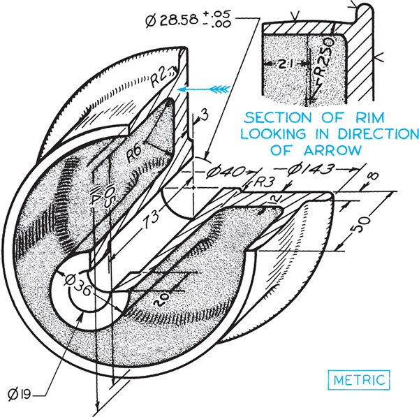
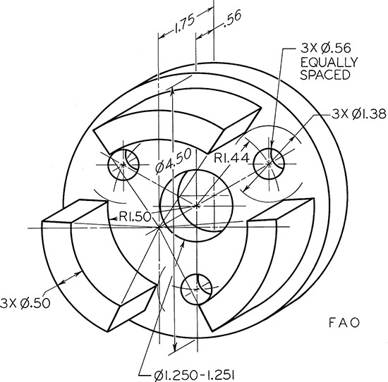
Exercise 8.17 Sheave. Draw two views, including half section.*

Exercise 8.18 Operating Valve. Given: Front, left-side, and partial bottom views. Required: Front, right-side, and full bottom views, plus indicated removed sections.*

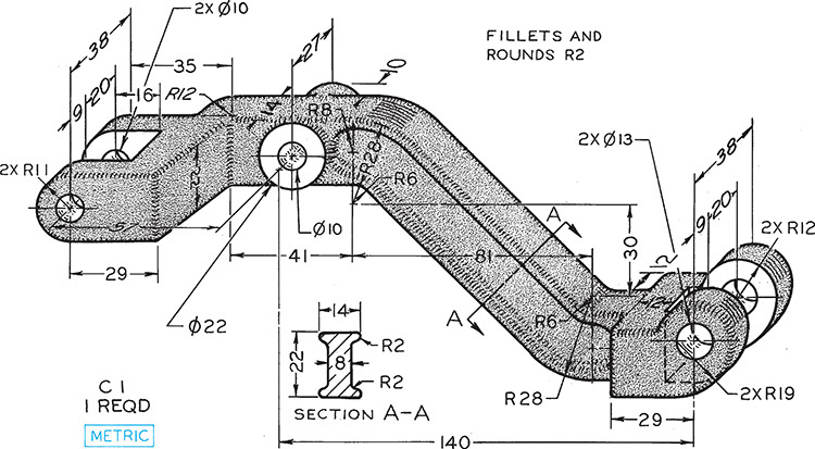
Exercise 8.19 Rocker Arm. Draw necessary views, with revolved sections.*
Exercise 8.20 Dashpot Lifter. Draw necessary views, using revolved section instead of removed section.*

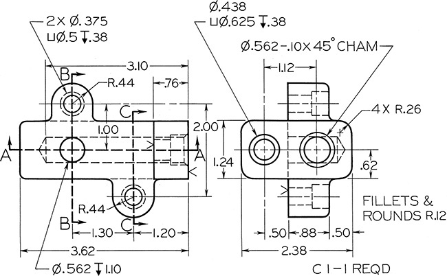
Exercise 8.21 Adjuster Base. Given: Front and top views. Required: Front and top views and sections A–A, B–B, and C–C. Show all visible lines.*
Exercise 8.22 Mobile Housing. Given: Front and left-side views. Required: Front view, right-side view in full section, and removed section A–A.*

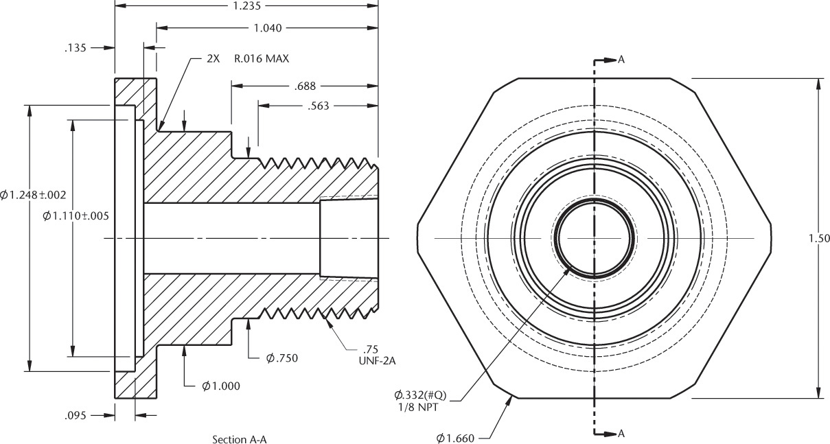
Exercise 8.23 Hydraulic Fitting. Given: Front and top views. Required: Front and top views and right-side view in full section.*
Exercise 8.24 Auxiliary Shaft Bearing. Given: Front and top views. Required: Front and top views and right-side view in full section.*
Exercise 8.25 Traverse Spider. Given: Front and left-side views. Required: Front and right-side views and top view in full section.*
Exercise 8.26 Bracket. Given: Front and right-side views. Required: Take front as new top; then add right-side view, front view in full section A–A, and sections B–B and C–C.*

Exercise 8.27 Gland. Given: Front, top, and partial left-side views. Required: Front view and right-side view in full section.*

Exercise 8.28 Cocking Block. Given: Front and right-side views. Required: Take front as new top view; then add new front view, and right-side view in full section. Draw double size.*
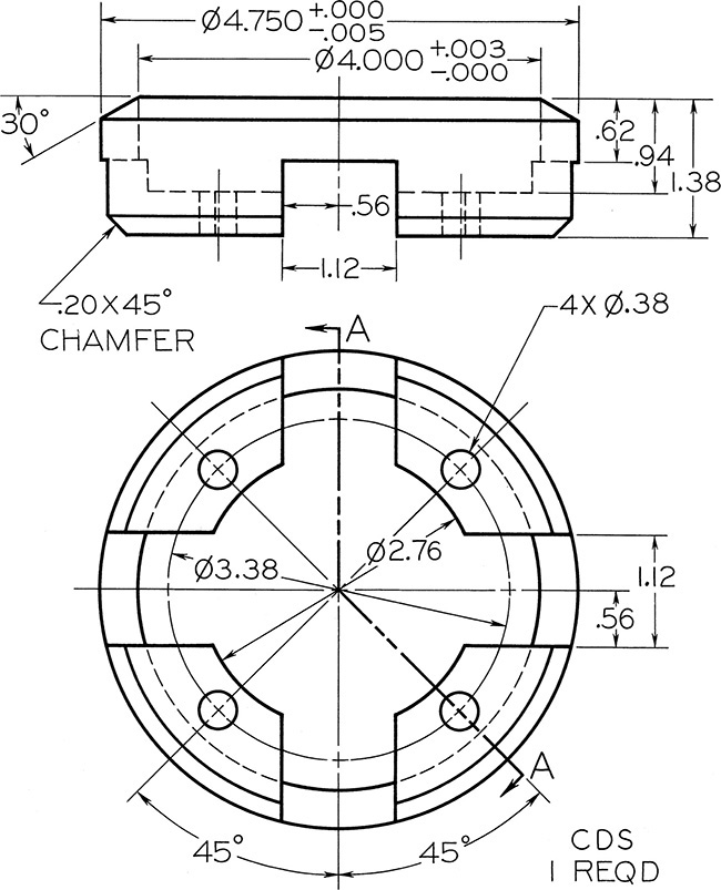
Exercise 8.29 Packing Ring. Given: Front and top views. Required: Front view and section A–A.*

Exercise 8.30 Strainer Body. Given: Front and bottom views. Required: Front and top views and right-side view in full section.*

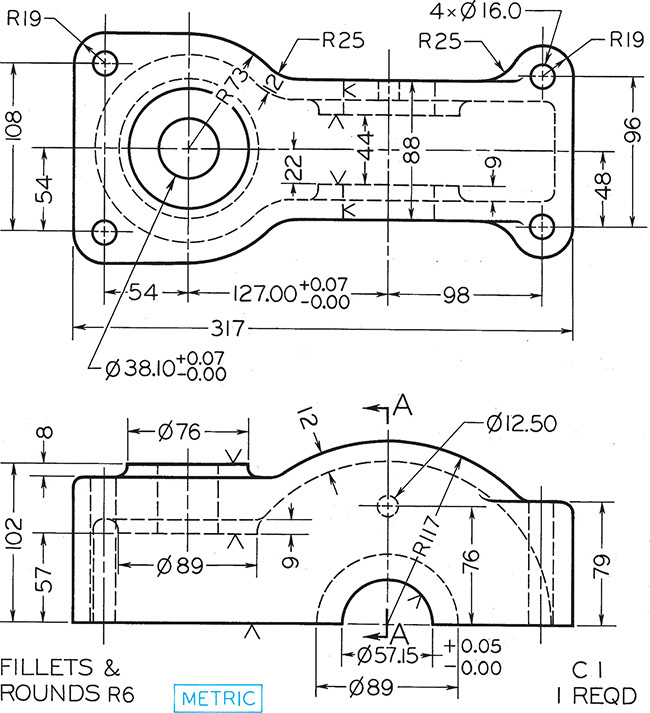
Exercise 8.31 Oil Retainer. Given: Front and top views. Required: Front view and section A–A.*
Exercise 8.32 Gear Box. Given: Front and top views. Required: Front in full section, bottom view, and right-side section A–A. Draw half size.*

Exercise 8.33 Slotted Disk for Threading Machine. Given: Front and left-side views. Required: Front and right-side views and top full-section view. Draw half size.*

Exercise 8.34 Web for Lathe Clutch. Given: Partial front and left-side views. Required: Full front view, right-side view in full section, and removed section A–A.*

Exercise 8.35 Support. Draw necessary views adding a section view.
Exercise 8.36 Bushing. Draw necessary views with a broken out section.*
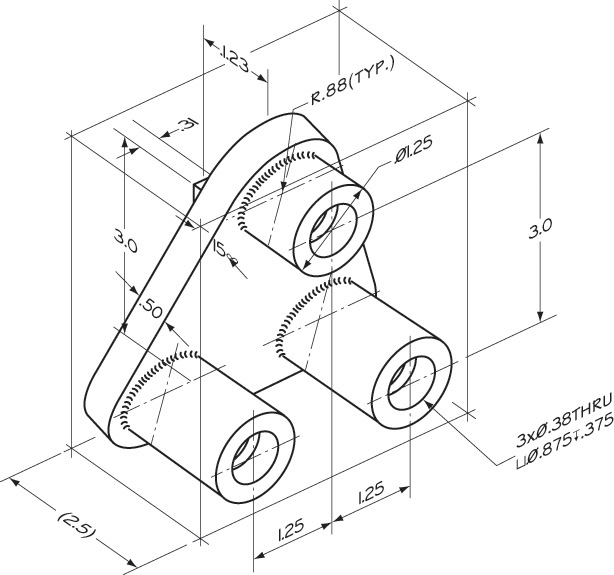
Exercise 8.37 Plastic Spacer. Draw all necessary views using an aligned section.*

Exercise 8.38 Motor. Draw all required views with one half section.*
Exercise 8.39 Mounting Pin. Draw the necessary views showing the front view as a half section.*

Exercise 8.40 Clamp. Draw the necessary views showing the front view as a full section.*
*Leave out dimensions unless assigned by your instructor.