Chapter 4. motion
Seeing your creation move is one of the most exciting and fascinating things about making a robot. Using the EV3 set, you can create vehicles, robotic arms and grippers, medieval siege engines, and many other moving contraptions. Combine it with your other LEGO sets, and you can create an almost unlimited variety of autonomous or remotely controlled models.
We can thank the EV3 motors for making this movement possible. In this chapter, you’ll learn about the motors and the programming blocks that control them. We’ll begin with very simple programs and work up to more complex ones.
the EV3 motors
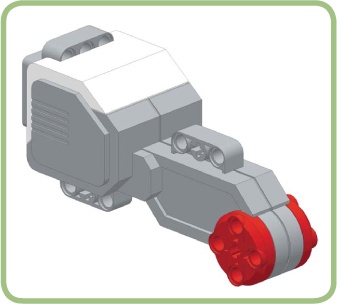
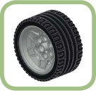
The Large motor (Figure 4-1) makes it easy for you to create moving robots. Its case has an unusual shape because it contains a set of gears in addition to the electric motor. The gears adjust the speed and power of the motor’s rotation, making it possible to connect a wheel directly to the motor without the need for additional gears.
The Medium motor (Figure 4-2) is smaller and has a more regular shape that makes it easier to incorporate into a robot. This motor turns faster than the Large motor and is ideally suited for moving grippers or arms. On the other hand, it’s not as powerful as the Large motor, so it’s not as effective for powering a mobile robot.

Each EV3 motor contains a built-in Rotation Sensor to measure the rotation of the motor. Because this sensor is part of the motor, you don’t have to connect the motor to one of the four sensor ports to use it. The blocks that control the motors (discussed next) automatically use this sensor to make very precise movements. You can also use this sensor to control the robot’s movement. (Chapter 5 discusses sensors, including the Rotation Sensor.)
the move steering block
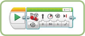
The Move Steering block (Figure 4-3) controls the two large EV3 motors. This is the block you’ll typically use to make your robot move. It has many options and can perform a wide variety of tasks.
The Move Steering block automatically keeps the two motors synchronized by constantly adjusting how fast each motor moves so that the two wheels work together. It uses the motors’ Rotation Sensors to move the robot in a straight line, turn it, or even spin it in place, based on the setting of the Steering control (discussed later in this chapter).

For example, the following simple program moves the TriBot forward a short distance:
Create a new project named Chapter4.
Change the name of the program to SimpleMove.
Drag a Move Steering block from the Action palette onto the Programming Canvas. Leave all the settings with the default values. Your finished program should look like Figure 4-4.
Save the project.
Download and run the program. Your robot should move forward a few inches.
Even though the Move Steering block’s default values work for the simple program above, you’ll probably want to customize it by changing the parameters along the bottom and top of the block. The settings you choose will depend on how you construct the robot and what you want it to do.
Note
From here on, I won’t include a step that tells you to save your project, but you should still save often— especially after making significant changes and before downloading and running your program.
mode
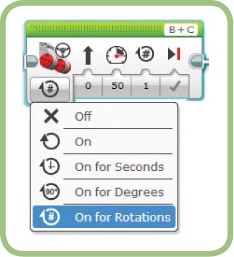
You can tell the block what you want it to do using the Mode Selector (Figure 4-5). Use the three On for modes to run the motors for a certain number of rotations, degrees, or seconds before running the next block in your program. The On mode turns the motors on, and then the program immediately runs the next block. The motors stay on until the program ends or they’re turned off by another block. The Off mode turns off the motors.
After you select a block’s mode, the block displays the options that are relevant to that mode. The following sections describe the options available for the Move Steering block and offer some programs to try. Rather than create a new program for each experiment, just create one program and use it for each new test.
Create a new program and name it Tester.
Add a Move Steering block to the program.
At this point, the Tester program should look like the SimpleMove program shown in Figure 4-4.
steering
The Steering parameter (Figure 4-6) controls the direction in which your robot moves. Possible values range from -100 to 100 and can be set by entering a number in the box or moving the slider.
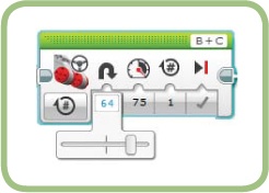
Move the slider to the middle or enter 0 to make the robot move straight. That is, the EV3 will try to make the robot go straight by constantly making small adjustments to the motors to keep them moving at the same speed. Many things can affect how a robot moves, and your program can only control how fast it moves each motor. If your robot is unbalanced, meaning there is more weight on one side than the other, it will tend to drift to one side.
Note
The type of floor on which your robot is moving will affect its motion, as well as the wheels and the type of caster (third wheel) you use. It’s almost impossible to make your robot move perfectly straight, but you can get close enough for most situations.
If you set the slider all the way to either side or enter -100 or 100, the robot spins in place because the two motors are moving at the same speed but in opposite directions. The distance between the two wheels determines how long the wheels must turn to make your robot spin in a full circle.
If you set the Steering slider somewhere between the middle and one of the ends, the robot makes a gentle turn. The closer the value is to -100 or 100, the tighter the turn will be. To make a turn, the EV3 slows down or stops one of its motors. For very sharp turns, it moves one motor backward and the other forward. If you select the On for Degrees or On for Rotations mode, the duration you set will apply to the faster-moving motor, which is the one on the outside of the curve.
When you are experimenting with different Steering parameters, a single rotation is a little too short to see the full effect of different values. Change the Rotation parameter to five rotations to give yourself a better sense of how the robot moves.
Change the Rotations parameter to 5.
Change to Steering parameter to 100. Here’s how the program looks with these changes:
Download and run the program. The TriBot should spin in a circle. Try using several other values for Steering to get a feel for how they affect the TriBot’s motion.
power
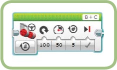
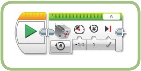
The Power parameter (Figure 4-7) controls how fast the motors move. Set the Power by moving the slider or by entering a value from -100 to 100. Positive values make the motors move forward and negative ones move the motors backward. A setting of 100 makes the motors move as fast as they can, and 0 keeps the motors still.
The next set of changes will make the TriBot move in a straight line at full speed.
Set the Steering parameter to 0.
Set the Power parameter to 100.
Download and run the program above to see how fast your robot can go, and then try different Power parameters while keeping the Steering parameter at 0. Next, try adjusting both the Steering and Power parameters. You’ll notice that the TriBot can be a little unstable when trying to make a sharp turn while moving very fast.
duration
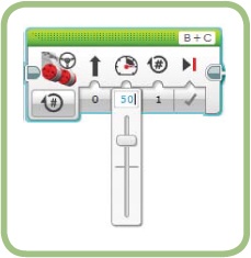
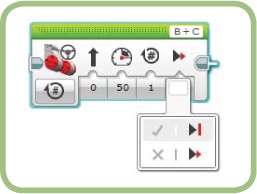
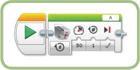
When you use one of the On for modes, you’ll need to set the Duration parameter in rotations, degrees, or seconds. Figure 4-8 shows the block with On for Seconds mode selected, and the Duration set to 1 second. Notice that the small icon above the Duration value changes to match the mode. For example, a small clock is shown for the On for Seconds mode.
The relationship between rotations and degrees is simple: 360 degrees will turn the motor exactly one rotation. It’s usually simpler to measure a long move in rotations and a short one in degrees because the numbers are easier to work with.
When using rotations or degrees, you can use a negative number to make the motors move backwards. (You can’t use a negative number when setting the Duration in seconds because time travel is not supported by the EV3.)
brake at end
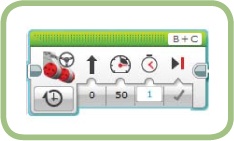
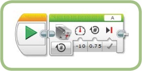
The Brake at End parameter (Figure 4-9) tells the block how to stop moving and what to do with the motors after the move is complete. The first option (set with a checkmark) quickly stops the motors and locks them in place. The second option (set with an X) allows the motors to spin freely until they stop on their own. These options are often called Brake and Coast, respectively.
As currently written, the Tester program doesn’t show the full effect of the Brake setting. After the robot moves forward, the block stops the motor, the program ends, and the EV3 stops trying to hold the motor in place—but the TriBot will still have enough momentum to move forward a bit. To see the real effect of this setting, add a Wait block in Time mode to pause the program for two seconds after the Move Steering block executes. This gives the robot time to come to a complete stop before the program ends.
To make your robot stop accurately, use the Brake setting when using the On for Rotations or On for Degrees modes. The motor should stop very close to the duration you set. If you use the Coast option, the motor merely slows down after reaching the duration and consequently moves a little past the target you set.
Use Brake to keep a motor from moving after the block finishes. For example, if the motor controls a gripper, use Brake to hold the motor still after grabbing an object; this will prevent the object from slipping.
Holding a motor in place uses extra battery power, so set a motor to Brake only if you need to hold it in place.
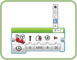
port
You can use the Port parameter (Figure 4-10) to tell the EV3 which two motor ports to move. Click the left or right motor port (B and C in Figure 4-10) and a menu appears which allows you to select a port. The top choice, marked with the small black block, is for using data wires, which I discuss in Chapter 8.
By default, the Move Steering block selects motor port B for the left motor and port C for the right motor. If you don’t select the correct ports, and you swap the left and right motors, the Steering parameter will make the robot steer in the opposite direction.
The EV3 software has a feature called Auto-ID, which lets the EV3 software know which motors and sensors are connected to your brick. It can also change the default port that a block uses. For example, when you add a Medium Motor block to your program, it will usually set the port to A. However, if you have the Medium motor plugged into another port when you add a Medium Motor block, the block will use that port by default (as long as your EV3 Brick is connected to the software).
port view
When using the Move Steering block’s On for Rotations or On for Degrees mode, setting the Duration and deciding on the correct value can be time-consuming. The Port View (Figure 4-11) can be a big help because it can show you how far each motor has moved. Select the middle tab on the Hardware page to show the Port View. (The MINDSTORMS environment must be connected to the EV3 for this window to show you anything useful.)

The Port View shows which ports have motors and sensors attached, as well as the type of motor or sensor. The value above a motor is from the motor’s rotation sensor: It represents the total distance the motor moved. As an example, if you move the motor forward 360 degrees and then backward 360 degrees, this value is 0. By default, the value for a motor is displayed in degrees. Click the motor to display a menu that allows you to select rotations. (I’ll discuss Port View in more detail in Chapter 5, when I discuss sensor types.)
When the EV3 is not running a program, you can move a motor manually to see how many degrees it moves. This is a particularly useful way to determine how far to move an arm or gripper. You can move a motor by hand to determine the distance you want it to go, and then enter that value into one of the move blocks. To reset the value to 0, click the port letter (A, B, C, or D).
When you run a program, the values are reset to 0 at the start and updated while the program is running. You can add Wait blocks to make the program pause if you want to check the values at various steps.
the EV3 intelligent brick view menu
The Port View has two drawbacks: You need to keep the EV3 connected to the computer, and you need to be sitting in front of your computer to see it. Alternatively, you can measure how far a motor moves using only the menu on the EV3 Brick. To do so, select the third main tab (along the top of the display) and then Port View. Select one of the motor ports, and when you move the motor that’s attached to the selected port, the EV3 display should show how far it moves.
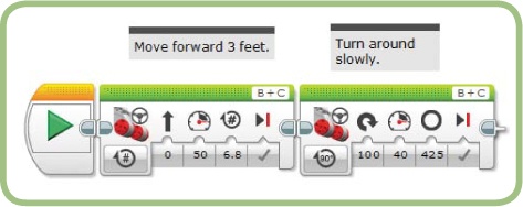
the ThereAndBack program
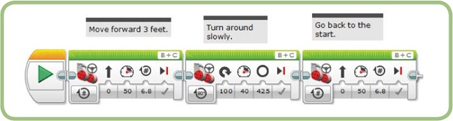
Let’s use the Move Steering block in a couple of programs. The ThereAndBack program will make the TriBot move forward three feet, turn around, then return to where it started. Some measuring is required to solve this problem, so if your rulers are metric, feel free to change the problem to use one meter instead of three feet.
This program uses three Move Steering blocks: one to move forward, one to spin the robot around, and one to move the robot back to where it started.
moving forward
The first block needs to move the robot forward three feet, but feet isn’t one of the duration options. How do you figure out how far three feet is in degrees or rotations? Let’s consider rotations.
One way is to write a program that moves the robot a long distance, say, 10 rotations. Before running the program, mark your robot’s starting position on the floor (a piece of tape should do), run the program, and measure how far the robot moves in inches. Divide the distance moved by the number of rotations to determine how far the robot moves in one rotation. For example, my robot moves 51 inches in 10 rotations, or 5.1 inches in a single rotation. The robot needs to go 36 inches, so I divide 36 by 5.1 to find the Duration setting needed to move 36 inches. Start with that calculated value and adjust the setting until you get what you need.
Be aware that the number you need will vary slightly if you change the type of floor the robot is moving on, the wheels you use, or the block’s Power parameter. A duration of 6.8 rotations at a Power of 50 worked well for me.
Note
Because the tires from the Education Edition are bigger than those in the Home Edition, they roll farther in one rotation. A Duration of 5.4 will move the robot 36 inches when using these tires.
When you know the duration, you can start writing the program. Here’s the first set of steps:
Create a new program called ThereAndBack.
Add a Move Steering block next to the Start block. The mode will be set to On for Rotations by default.
Set the Rotations parameter to the number you calculated.
Figure 4-12 shows the program at this point.

Test these settings by running the program several times across a measured distance. Your robot should stop very close to the same spot each time. If it doesn’t, try lowering the Power parameter. Adjust the Duration if the robot stops at the same spot but doesn’t travel the correct distance.
turning around
A second Move Steering block will turn the robot around for the return trip. Move the Steering slider all the way to one side to make the TriBot spin. (Choose either side; the direction isn’t important.)
Once again, the challenge in configuring this block lies in figuring out the duration value. After some testing, I found that a duration setting of 425 degrees worked well (325 degrees using the Education Edition tires). I turned the Power down to 40 to get a good, consistent turn because with the Power at 50, it turned a little too far about half the time. This is a typical trade-off between speed and accuracy.
Here are the next steps in building this part of the program:
Drag a Move Steering block after the existing Move Steering block.
Set the mode to On for Degrees.
Drag the Steering slider all the way to one side.
Set the Degrees to 425 and the Power to 40. Use these for initial values; you can adjust them as needed during testing.
Figure 4-13 shows how the program should look with this new block added.
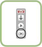
testing a single block
To fine-tune the Degrees and Power parameters, it’s easier to test the block by itself over and over instead of waiting for the robot to travel three feet and then seeing whether it turns around correctly. The Run Selected button (Figure 4-14) will run a single block or a group of blocks. If you select the second Move Steering block and then click Run Selected, your robot should only turn around (instead of moving three feet first). Adjust the Degrees and Power parameters as needed until your robot consistently turns all the way around.
moving back to the start
To move the TriBot back to where it started, add a third Move Steering block that travels the same distance as the first. The final steps in the program are as follows:
Place a Move Steering block at the end of the program.
Set the Rotations and Power to the same values you used for the first Move block.
Figure 4-15 shows the final program.
Test your completed program. A slight error in the duration of the second block may show up after the TriBot travels back the three feet, so you may need to adjust the Power or Degrees parameter of the second Move block. When things are working well, try increasing the speed to find the point where the consistency of the program starts to suffer. You should notice that the robot starts to turn too far or fails to get back to the starting point if it’s going too fast. When moving very fast, the wheels tend to slip more, and other issues, such as imbalance in the robot, can cause more apparent errors.
the AroundTheBlock program
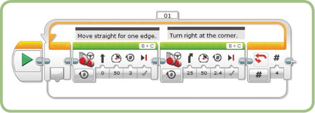
The AroundTheBlock program will make the TriBot travel in a square pattern and end up where it started. For this example, I’ll use a square that is three rotations long on each side. At the corner, the robot can move in a gentle curve to produce a smoother motion, rather than just spinning in place.
To travel in a square, the robot needs to move along a side and turn a corner, move along the next side and turn a corner, and continue like this for all four sides.
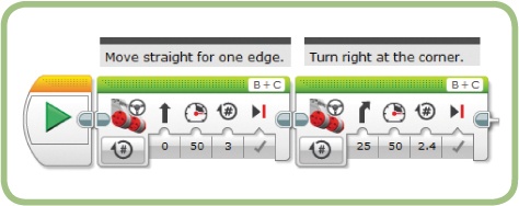
the first side and corner
The first part of the program uses two Move Steering blocks to move the TriBot straight and make the first turn. To move along the edge, just set the duration to three rotations. To turn the corner with a gentle curve, set the Steering to 25.
The next step is to find the Duration value that gives you an accurate turn around the corner. I found that 2.4 rotations worked well (or 1.8 using the Education Edition tires). Your setting might differ due to factors like the Steering parameter and surface you use. Here’s how to build this part of the program:
Create a new program called AroundTheBlock.
Add a Move Steering block after the Start block.
Set the Rotations parameter to 3.
Add a second Move Steering block to the program.
Set the Rotations parameter to 2.4.
Set the Steering parameter to 25.
Figure 4-16 shows the program at this point.
the other three sides and corners
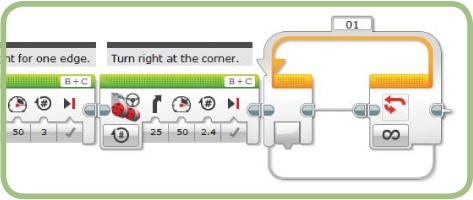
Now extend the program to go all the way around the square. You could add six more Move Steering blocks and use the same settings for the other three edges and corners, but that would be tedious. And imagine what would happen if you wanted to go around the square 10 times—you would need to add 78 more blocks! An easier way is to use the Loop block.
The Loop block (Figure 4-17) lets you run a group of blocks multiple times. You’ll find the Loop block on the Flow Control palette, next to the Wait block. You can run the two Move blocks four times (once for each side of the square) by placing them inside a Loop block. (We’ll learn more about the Loop block in Chapter 6.)

Drag a Loop block onto the end of the program. Your program should look like this:
Drag the two Move blocks to the middle of the Loop block. The Loop block should expand as you drop in the Move blocks. Now the program should look like this:

Note
If you added comments above the two Move Steering blocks, be sure to move them so that they stay above the blocks they describe. Comments don’t automatically move with the blocks, so another option is to make a habit of adding them after you edit your program.
The Loop block has lots of different modes, including one or more for each type of sensor. When you first add the Loop block to your program, it should have the Unlimited mode selected, as indicated by the infinity symbol on the bottom of the right side of the block (Figure 4-18). For this program, you need to change the mode to Count, which will let you configure the block to repeat four times.
Follow these steps to make the loop execute four times:

Click the Mode Selector and choose Count. A box appears to the right of the Mode Selector for entering the number of times the loop should repeat.
Enter 4 for the Count parameter.
Figure 4-19 shows the complete program.
testing the program
When you run the program, your TriBot should make a complete square. If it doesn’t end up where it started, adjust the duration for the second Move Steering block. This “turning” block runs four times, and errors will accumulate as the robot moves around the square. The goal is to make the margin of error small enough so that it has little impact on your program, which for this program means getting reasonably close to the starting position.
the move tank block
The Move Tank block (Figure 4-20) is like the Move Steering block except that it has one Power parameter for each motor.
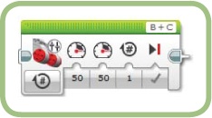
The robot’s direction of movement depends on how the two Power parameters are set. If both have the same value, the robot will move straight. If the values differ, the robot will turn, and the sharpness of the turn will depend on how different the values are. If they have opposite values (one positive and one negative), the robot will spin.
As you’ve seen, you can get similar behavior with the Move Steering block, but by explicitly setting the Power level of each motor, the Move Tank block gives you a little more control. For example, when you use a Move Steering block with the Power set at 50 to turn the corner, the outside motor keeps moving at Power of 50 and the other motor slows down. On the other hand, you could use the Move Tank block to speed up the motor on the outside of the curve, or slow one motor down and speed the other up.
Note
The Move Steering block is modeled after the way a car is driven: The Power parameter is the accelerator, and the Steering parameter is the steering wheel. The Move Tank block is modeled after the way tracked vehicles like tanks and bulldozers work. It can be more natural to use the Move Tank block in programs for robots that use treads instead of wheels.
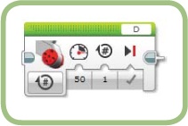
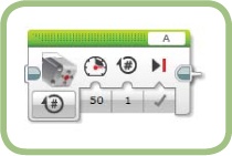
the large motor and medium motor blocks
Use the Large Motor block or the Medium Motor block (Figure 4-21 and Figure 4-22) when you want to move a single motor. The difference between these two blocks is the type of motor they control and the default Port setting. The default port is D for the Large Motor block and A for the Medium one. The modes and other parameters for both blocks are identical to those of the Move Steering block, except that there is no Steering control because these blocks only control one motor.
the lift arm
Let’s use the Lift Arm (Figure 4-23) to experiment with the Medium Motor block. This Lift Arm could be used to make a robot lift beams or blocks—or, turn it over and it can capture a ball. With a little adjustment in the gears, you could also turn it into a small catapult.

Start with the arm pointing out horizontally as in Figure 4-23. To move the arm by hand, gently turn the gear attached to the motor. If you try to move the arm directly, the resistance from the motor tends to make the parts separate or the gears slip.
Let’s start by seeing how a Medium Motor block behaves with the default settings.
Create a new program named LiftArm.
Connect the Medium motor to port A on the EV3 using the long (20 inches or 50 cm) cable.
Add a Medium Motor block to the program. The program should look like this:
Run the program and you should see the hook connected to the large gears move down and press against the surface below it, lifting up the motor and the rest of the mechanism. From this test, you can tell one important thing: A positive Power value moves the arm downward. Move the arm back to horizontal manually and then try the program with a negative Power value. What happens?
Run the program now, and the Lift Arm should move up and then stop a little past the point where it’s pointing straight up. The arm should have moved about a third of the way around a complete circle, or 120 degrees.
The block is set to move the motor one rotation (360 degrees), so why does the arm move only one-third of this distance? The reason lies in the fact that the smaller gear has 12 teeth and the larger one has 36 teeth. Because the smaller gear has to go around three times to make the larger one go around once, you can use a small Power level in the Medium Motor block to make the arm move very smoothly.
Move the arm back to the horizontal position and try a move with a low Power value.
Run the program and you should see the Lift Arm move smoothly from a horizontal to a vertical position.
the invert motor block
The Lift Arm moves down when a positive Power level is used because of the way the four-tooth gear on the motor connects to the four-tooth gear on the axle. Of course, it’s more intuitive for a positive Power level to move the arm upward. You could rebuild the Lift Arm (just move the gear on the axle to the other side of the motor), but why not fix it with a block? The Invert Motor block (Figure 4-24) on the Advanced palette will do just that.
The Invert Motor block reverses the meaning of the Power parameter for the motor connected to the selected Port.
Add an Invert Motor block between the Start block and the Medium Motor block. The Port parameter should default to A, so you shouldn’t need to make any changes.
Change the Power parameter on the Medium Motor block to 10. The final program should look like this:
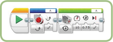
Run the program and it should behave exactly like the previous version, except that now the number for the Power parameter is positive.
a problem with coasting
All the motor control blocks have a Brake at End parameter with the choices Brake and Coast, which we looked at earlier. When the Coast setting is combined with either the On for Rotations or On for Degrees mode, these blocks behave in a way that might be unexpected: After coasting to a stop, the next movement seems to be a little shorter or a little longer than what you specified.
When you run a motion block using these settings, the firmware keeps track of how far the motor actually moved (the firmware is the program that runs on the EV3 and executes the program you write). Because the motor coasts to a stop, it will move a little more than the duration you specified, and the next motion block that runs will adjust its duration to account for the extra distance.
The next program, CoastTest, will demonstrate this. You’ll use a couple of Move Steering blocks to move the motors and use Port View to see how far the motors go. Finally, I’ll show you how to avoid this behavior if it’s causing a problem for your program.
Create a new program named CoastTest.
Add a Move Steering block and keep all the default settings.
Add a Wait block after the Move Steering block. Set the time to 5 seconds.
Add another Move Steering block to the end of the program.
Add another Wait block to the end of the program. Set the time to 5 seconds.
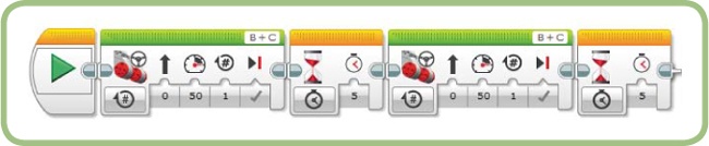
The program should look like Figure 4-25.
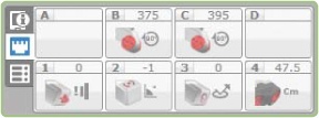
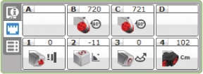
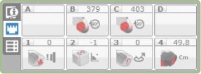
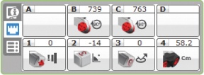
At this point, both Move Steering blocks are set to brake at the end of the move. Run the program and watch the motor positions using the Port View. Figure 4-26 shows the Port View after the first Move Steering block, and Figure 4-27 shows it after the second one. Notice that both blocks worked as expected: Each one moves the motors almost exactly 360 degrees.


Note
While a program is running, a moving pattern of white diagonal strips appears on the colored bar at the top of the currently executing block.
Now modify the program so that the first Move Steering block coasts to a stop.
Change the Brake at End parameter for the first Move Steering block to False. The block should now look like this:

Run the program again and watch the Port View. Figure 4-28 and Figure 4-29 show the Port View after the first and second Move Steering blocks, respectively.
The first Move Steering block moved the motors one rotation, and then they coasted a bit farther (an extra 15 to 35 degrees in this case). Next, instead of making the motors rotate an additional 360 degrees, the second Move Steering block moved the motors just enough so that the total distance covered was two rotations, or 720 degrees (to within one degree). Whether this behavior is “correct” or not really depends on what you wanted the program to do. If you wanted the robot to move a total of 720 degrees, this program works fine, but if you want it to move an additional 360 degrees with the second block no matter how much the robot has moved so far, what do you do?
The problem we need to solve is that the firmware tracks how far the motors coast after a move completes and then uses that information for the next move. To cancel this offset, use a Move Steering block in Stop mode with the Brake at End parameter set to Brake.
Place this block just before the second Move Steering block in the CoastTest program. Because the TriBot isn’t moving at this point in the program, the new block should only cancel the offset caused by the previous coasting.
Add a Move Steering block between the first Wait block and the second Move Steering block.
Set the new block’s mode to Off.
The program should now look like Figure 4-30. Run the program and watch the Port View.
Figure 4-31 and Figure 4-32 show the Port View after the first and second Move Steering blocks, respectively. This time, the first Move Steering block moved the motors 360 degrees, and then it coasted a little farther. The second Move Steering block moved the motors an additional 360 degrees. Adding the new block changed the behavior so that the final Move Steering block moved the full distance.

further exploration
Try these activities for more practice using the blocks introduced in this chapter:
Use the coast option with the ThereAndBack program. Do you notice any change in the transitions between the moves? How does this affect how closely the TriBot gets back to the starting point?
Modify the AroundTheBlock program to use Move Tank blocks instead of Move Steering blocks. First try to replicate the existing turning motion, and then experiment with different combinations of Power settings for the two motors.
Write a new program that uses the same method as the AroundTheBlock program to travel in a triangle instead of a square.
Set up a simple obstacle course and program the TriBot to go through it using a sequence of Move Steering or Move Tank blocks. Notice that getting the TriBot to repeat the same pattern gets more difficult as you add more steps.
conclusion
The EV3 set comes with three motors designed to make it easy to build a wide variety of robots. The EV3 software provides several blocks for controlling the motors, giving you lots of flexibility when deciding how your robot should move. The Move Steering block is the most common choice because it’s simple to use and its ability to synchronize two motors makes it easy to program a two-wheeled robot. The Move Tank block gives you a little more control over each motor. The Large Motor and Medium Motor blocks allow you to control a single motor.
The example programs showed you a few different ways to use these blocks, including one that moves the TriBot around a square. At this point, you should be able to program your robot to follow any course by combining motion blocks. You’ll get plenty more practice using the motors in subsequent chapters.