Chapter 11. variables
Variables let you store a value and use it later in the program. For example, say you want to take a sensor reading and then compare that reading to other sensor readings in the future. To do this, you would save the first sensor reading to a variable, which you could access later and compare to other readings. In this chapter, I’ll show you how to use variables and describe the types of problems they solve. I’ll also show you how to use the Constant block, which lets you use a single value to control multiple blocks throughout your program.
the variable block
Think of a variable as a place in the Brick’s memory where you can store a value. The Variable block, found on the Data Operations palette, can either store or retrieve a value from a variable. You can store any value from a data wire in a variable (this is called writing to the variable). Then, later in your program, you can retrieve that value (this is called reading the value) and use it as the input to other blocks.
To demonstrate how variables are used, we’ll create the VariableTest program, which stores the reading from the Color Sensor in a variable, reads the value out of the variable, and displays it. A Color Sensor block in Measure Color mode provides the reading, followed by a Variable block to store the value.
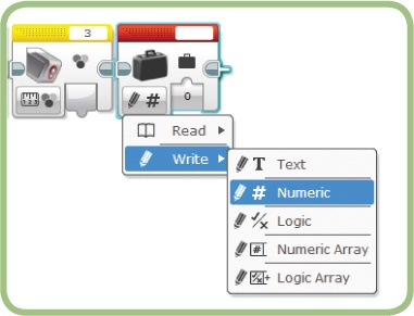
The first thing we need to do with a Variable block is set the mode, which selects the operation (read or write) to perform on the variable and the data type of the variable (see Figure 11-1). To store the reading from the Color Sensor (which is a Number value), select Write Numeric mode. I’ll use only simple data types (Text, Numeric, and Logic) in this chapter. I’ll discuss Array data types in Chapter 15.
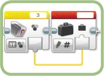
The Write operation stores a value in the variable. That value can be supplied by manually entering a value or by using an input data wire. For this program, we’ll connect the Color Sensor block’s output plug to the Variable block’s input plug (see Figure 11-2). In other programs, you could manually set a variable’s initial value and then use a data wire to change the value later in the program.
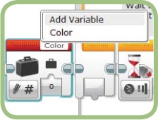
After setting the mode, set the name of the variable by clicking the box at the top right of the block. A menu appears that shows all the variables of the selected data type that have previously been defined, along with an option to add a new variable (see Figure 11-3). Because we haven’t added any variables to this project, the only choice is Add Variable.

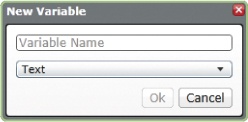
Selecting Add Variable displays the New Variable dialog (see Figure 11-4). Type the name you want to use to create a new variable. Each variable can only hold values of one specific data type (Text, Numeric, Logic, Numeric Array, or Logic Array). When you create a variable, the mode of the Variable block determines the data type that the variable can hold. For this program, we’ll name the variable Color.

Now we need to add another Variable block to read the value, and a Display block to show the value on the EV3 screen. A Wait block at the end of the program prevents the display from clearing before you have a chance to see the result. Figure 11-5 shows the completed program.
After you add the three new blocks to the program, set the new Variable block’s mode to Read Numeric. The Variable Name is automatically set to Color because that’s the only Numeric variable in the project, but in most cases you’ll need to click the Variable Name box and select the variable. The final step in building this program is connecting the output of the Variable block to the Display block’s Text parameter.
When you run this program, it reads the Color Sensor, stores the reading in the Color variable, reads the variable, and finally displays the value. To see the value passed into and out of the Variable blocks, connect the EV3 to your computer and run the program from the EV3 software. Then you can examine the values on the data wires while the program is running, as shown in Chapter 8 (you might want to set the Wait block to pause longer so you have more time to see the values).

the RedOr-BlueCount program
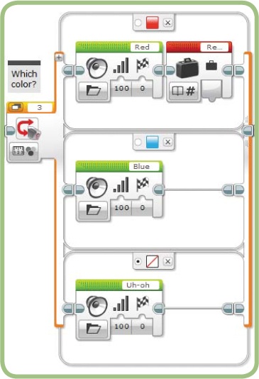
In this section, I’ll take you through the steps for creating the RedOrBlueCount program based on the RedOrBlue program from Chapter 6 (shown in Figure 11-6). The new program uses two variables, named Red Total and Blue Total, to keep track of the number of red and blue objects. As the program runs, it displays the running totals on the EV3 screen. When the program first starts, the count for both colors is zero, so it should display “Red: 0” and “Blue: 0”. After that, it should update the display as the count increases. Example 11-1 shows the pseudocode for the program with the parts you’ll add to the original RedOrBlue program in bold. Note that the program doesn’t count the objects that are neither red nor blue.

set Red Total to 0
set Blue Total to 0
display "Red: 0"
display "Blue: 0"
begin loop
   wait for the Touch Sensor to be bumped
   if the object is red then
      use a Sound block to say "Red"
      read the Red Total value
      add one to the Red Total value
      write the new value to Red Total
      display "Red: " followed by the Red Total
         value
   else if the object is blue then
      use a Sound block to say "Blue"
      read the Blue Total value
      add one to the Blue Total value
      write the new value to Blue Total
      display "Blue: " followed by the Blue Total
         value
   else
      use a Sound block to say "Uh-oh"
   end if
loop forever
creating and initializing the variables
The first step is to create the two variables and give each a starting value. This is called initializing the variables. To count the number of red objects, the Red Total variable needs to start at zero and increase by one each time a red object is detected. When the program begins, a Numeric variable will have 0 for a value by default. Still, I recommend always setting a variable’s initial value just in case you later move the code around or reuse part of the code in other programs.
Start building the RedOrBlueCount program by following these steps:
Make sure the Chapter11 project is open.
Open the Chapter6 project, and copy the RedOrBlue program to the Chapter11 project. Rename the new program (in the Chapter11 project) RedOrBlueCount.
Add a Variable block to the beginning of the program. Leave it in Write Numeric mode, with the value set to 0 (the default mode and value).
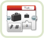
Choosing an appropriate variable name makes your program easier to understand. For example, in a program that counts red and blue objects, a name like Red Total makes it clear how the variable is being used (both for other people reading your program and for yourself if you look back at the program later). It’s helpful to be consistent with your variable names, too. For example, if you use Red Total for the number of red objects, then you should use Blue Total for the number of blue objects, not something different, such as Blue Count. By the same token, avoid names that are difficult to decipher or abbreviations that are too short, such as TtlR or just R. Also keep in mind that the space available for the name on the Variable block is limited, so avoid using really long variable names that start the same way. For example, if you used the names Total Red and Total Blue, then the Variable block looks the same with either name selected (see Figure 11-7), which makes it harder to tell what the program is doing. To see the full name of the variable, hover the cursor over the Name box.
Click the block’s Variable Name box. A menu pops up that contains the Add Variable choice and any Numeric variables that you’ve already created (see Figure 11-8).
Click Add Variable, and the New Variable window appears. Type Red Total (see Figure 11-9) and click Ok. The Variable block should now show the first few letters of the variable name (see Figure 11-10).
Add another Variable block, just to the right of the first one.
Type the Variable Name Blue Total.


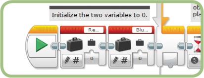
At this point, the beginning of the program should look like Figure 11-11. These two blocks initialize the two variables to 0.
displaying the initial values
To display the initial values, use two Display blocks placed before the Loop block:
Add a Display block after the second Variable block. Set the mode to Text Grid and the row to 2. Set the text to Red: 0.
Add another Display block after the first one. Set the mode to Text Grid and the row to 4. Set the text to Blue: 0.
Set the Clear Screen option to False.
The beginning of the program should now look like Figure 11-12.

counting the red objects
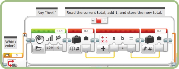
When a red object is detected, you want the program to add one to the Red Total variable and display the new value. To make that happen, you’ll use three blocks: a Variable block to read the current value and send it out on a data wire, a Math block to add one to the current value, and a second Variable block to store the new value. Here’s how to do that:
Add a Variable block to the red case of the Switch block, after the Sound block.
Set the mode to Read Numeric, and make sure the Variable Name is set to Red Total. The Switch block should now look like Figure 11-13.
Add a Math block after the Variable block. Make sure the b value is set to 1.
Add another Variable block after the Math block. Make sure the mode is set to Write Numeric. Select Red Total for the Variable Name.
Connect the blocks by drawing a data wire from the first Variable block to the Math block’s a input, and another data wire from the Math block’s output to the second Variable block’s input, as shown in Figure 11-14.
After the total has been updated, the program should display the new value using a Text block and a Display block. (This is the same technique that you used in the SoundMachine program in Chapter 8.)
Add a Text block after the second Variable block, and set the a value to Red:. (Be sure to include a space after the colon).
Connect the Math block’s Result output to the Text block’s b input.
Add a Display block after the Text block, and set the mode to Text Grid. Set the row to 2. Be sure to set the Clear Screen option to False so that you don’t erase the blue total while writing the red total.
Click the text box in the upper-right corner of the Display Box, and select Wired from the pop-up menu.
Connect the Text block’s Result output to the Text input plug that appears on the Display block.
This section of the program should now look like Figure 11-15.
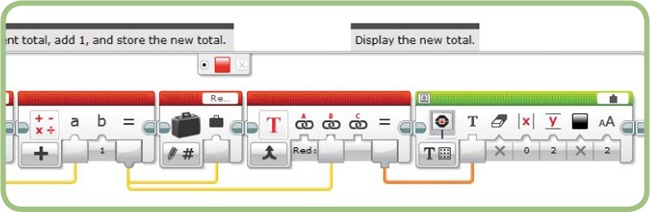
This section of code contains a pattern that you’ll often see to update a variable: Read the current value (with a Variable block), modify it (with a Math block), and write the new result to the variable (with another Variable block).
counting the blue objects
The code for counting the blue objects is almost identical to the code for counting the red objects, so instead of writing the code by hand, you can copy the code with a few changes. Here’s how to duplicate the code:
Select the five new blocks on the Switch block’s upper case (from the first Variable block to the Display block) by drawing a selection rectangle around them or by selecting the Variable block and then pressing SHIFT while clicking the other blocks.
While pressing CTRL, click one of the blocks and drag it to the lower case. (When you drag with the CTRL key pressed, the blocks are copied instead of moved.)
Set both Variable blocks to the Blue Total variable instead of Red Total.
Set the label in the Text block to Blue: (with a space after it).
Set the Display block to use row 4.
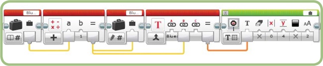
Figure 11-16 shows the section of the program on the lower case.
With these blocks copied and the parameters changed, your program should now correctly count and display the totals for both red and blue objects. Download and test the program to be sure it works for both colors.

managing variables using the project properties page
For the RedOrBlueCount program, you created the two variables by using Variable blocks. You can also create—and delete— variables using the Variables tab on the Project Properties page, which you open by clicking the wrench icon to the left of the program name tabs (see Figure 11-17).
The Variables tab shows the name and data type of all the variables used in the current project. To add a variable to the project, just click the Add button. The New Variable window pops up (see Figure 11-18) so you can set the name and data type of your new variable. You can also delete a variable if you’ve decided not to use it in your programs. To delete a variable, select it in the list and click the Delete button at the bottom of the window. If you delete a variable that a program still uses, the program continues to work but the variable won’t be listed on the Project Properties page or in the list displayed when you click the Variable block’s Name box.
the compare block
For the next program, you’ll use the Compare block to compare two numbers (see Figure 11-19). Let’s take a quick look at how this block works. The Compare block is on the Data Operations palette. You can supply the two Input values using data wires or by manually setting one or both of the parameters. The block compares these two values according to the mode selected, as shown in Figure 11-20, and the result is made available in the block output. For example, the block shown in Figure 11-19 is in Equal To mode, so it checks to see if the two values are equal and sends the result to the output plug.
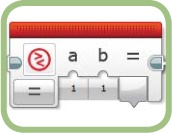

The result from the Compare block is always a Logic value (true or false). When using the Compare block, it’s like you’re asking a question such as “Is the value of the Ultrasonic Sensor greater than 20?” The answer will be a Logic value.
The Compare block is useful for making decisions because the resulting Logic value can be used to control Switch and Loop blocks, and it gives you more flexibility than just using a Switch or Loop block alone. For example, you can compare the readings from two Rotation Sensors, or you can use a Math block to modify a sensor value before comparing it with a Target value.
Typically, the Compare block is used as shown in Figure 11-21. Here, data wires give the block two numbers to compare. In this example, the mode for the block is set to Less Than.
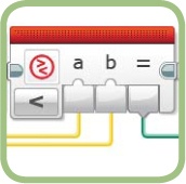
When the block runs, it compares the two input numbers and puts the resulting Logic value on the output data wire. For example, if the A value is 7 and the B value is 12, the result is true because 7 is less than 12. On the other hand, if A is 25 and B is 8, the result is false because 25 is not less than 8.
the LightPointer program
The LightPointer program demonstrates how to use variables to remember values that you want to use later in your program. This program uses the Color Sensor to point the TriBot at a light source by spinning the robot in a circle and remembering where the sensor detected the brightest light. The code and ideas you develop here could be used as part of a larger program, such as a flashlight-following program or a robot that finds the longest clear path through a field of obstacles.
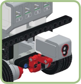
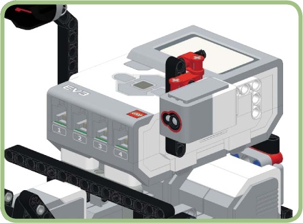
For this program, you can place the Color Sensor at the front of the TriBot (Figure 11-22) or on its side (Figure 11-23). You can, of course, adjust the placement of the sensor depending on the height of the light source.
This program has two distinct stages: First it searches for a light source, and then it points the TriBot at that light source. For the first part, the TriBot slowly spins in a circle as the sensor continuously measures the amount of ambient light. Each reading is compared with the largest reading seen so far, and when a larger reading is measured, the position is recorded.
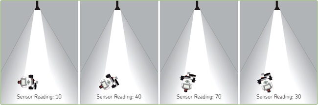
Figure 11-24 shows how the sensor reading changes as the TriBot spins. The robot starts facing away from the light, so the reading is low (10). As the robot spins toward the flashlight, the sensor reading increases to 40, as shown in the second image. When the TriBot is pointing directly at the flashlight, the reading is at its highest level (70 in this example). The sensor reading decreases as the TriBot spins past the flashlight, as shown in the final image.
The second part of the program turns the TriBot back to the position with the largest reading, which should result in the robot pointing at the light source.
defining the variables
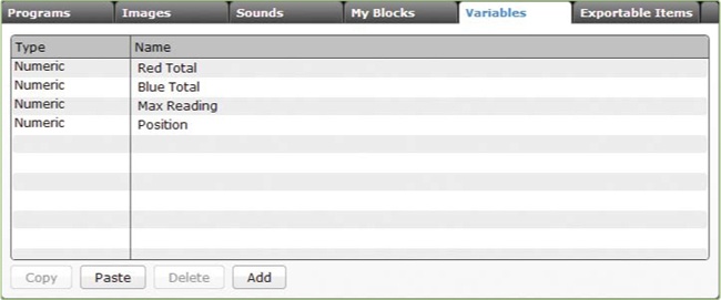
This program needs two variables to hold two different Numeric values. The first one, Max Reading, holds the brightest sensor reading so far. The other variable, Position, holds the robot’s position where Max Reading was measured. Create these two Numeric variables using the Variables tab on the Project Properties page. Remember to set the type to Numeric in the New Variable window. After creating the two variables, the Variables tab should look like Figure 11-25.
finding the light source
The first step in finding the light source is to spin the robot around. We’ll use a Move Steering block with the Steering value set at -100 to do this. We also want to track the robot’s position as it spins, and for that we’ll use the rotation value from the C motor, which increases as the TriBot spins.
The TriBot should spin in a complete circle so that it can find the light source in any direction. A little experimentation shows that a Duration parameter of 900 degrees moves the robot in a full circle. This value doesn’t have to be exact; the program will work just fine if the robot rotates a little past its starting point.
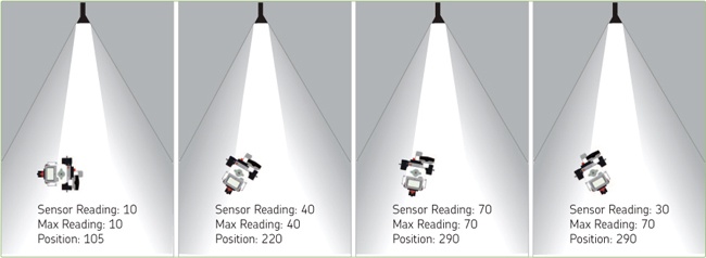
As the TriBot spins, the program compares the reading from the Color Sensor with the highest reading seen so far. If a higher reading is found, Max Reading is set to the new (higher) value and Position is set to the C motor’s position. Figure 11-26 shows what the variable values would be for the positions shown in Figure 11-20. Notice that in the fourth panel, the Max Reading and Position aren’t updated with the newest position and sensor reading because the sensor reading at that position is less than a reading the robot detected earlier.
Example 11-2 shows the pseudocode for this section of the program. Now that you have some experience with variables, I’ve shortened the notation a bit:
Max Reading = Color Sensor readingThe line above is a more concise way of saying “take the Color Sensor reading and store it in the Max Reading variable.”
This notation matches how you would update a variable in many other programming languages, where the equal sign means “store the value on the right in the variable on the left.”
creating the Lightpointer program
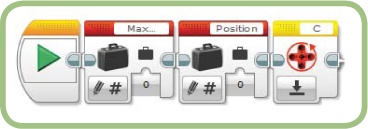
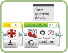
The first three blocks in the LightPointer program initialize the Max Reading and Position variables and reset the C motor’s Rotation Sensor, as shown in Figure 11-27.
With initialization complete, you can begin writing the code for locating the light source using the pseudocode developed in the previous section as a guide. First, start the TriBot spinning by using a Move Steering block, as shown in Figure 11-28. Set the Power to 20 to make the robot spin slowly so that it doesn’t miss the light source.
In the next part of the program, shown in Figure 11-29, a Loop block keeps the robot spinning until the Rotation Sensor reads greater than 900 degrees by using the Motor Rotation - Compare Degrees mode. Each time through the loop, the Color Sensor reading is compared with the Max Reading value. If the sensor reading is greater than the current Max Reading value, the code in the Switch block is executed. This code updates the Max Reading variable and sets the Position variable to the current motor position using the Rotation Sensor. There are no blocks on the other tab of the Switch block.
Let’s go through the blocks in this section one at a time.
The Loop block is configured to run until the reading from the Rotation Sensor for motor C is greater than 900. This keeps the loop body repeating until the TriBot has spun in a complete circle.
The Color Sensor block uses Measure - Ambient Light Intensity mode to measure the brightness of the light in front of the sensor. It sends this value to other blocks using data wires.
The Variable block reads the current value of the Max Reading variable and sends it to the Compare block with a data wire.
The Compare block compares the reading from the Color Sensor block with the Max Reading value. If the Max Reading value is less than the new sensor reading, the result passed to the Switch block is true; otherwise, the result is false.
If the result from the Compare block is true, the Switch block runs the three blocks on the true case shown in Figure 11-29. There are no blocks on the false case.
The first Variable block within the Switch block stores the latest Color Sensor reading in the Max Reading variable. The next time through the loop, the Compare block uses this value.
The Motor Rotation block reads the current position of the C motor.
The second Variable block stores the position of the C motor in the Position variable.
The Loop block runs until the TriBot has spun around in a complete circle. After the loop completes, the Position variable should contain the position of motor C where the brightest light was detected. The second part of the program uses this value to make the TriBot spin in the opposite direction and return to that position.
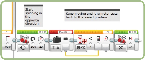
A Move Steering block with the Steering value set to 100 will spin the TriBot the other way around, causing the Rotation Sensor value for the C motor to decrease. The TriBot needs to keep spinning as long as the Rotation Sensor reading is greater than the Position value so that it ends up pointing in the direction where the brightest light was detected. Example 11-3 shows the pseudocode for this section of the program.
start the robot spinning slowly in the opposite
   direction from the first move
read the Position variable
wait until the Rotation Sensor reading reaches the
   Position value
stop the motors
Figure 11-30 shows this section of the program. Notice that the Wait block reads the Rotation Sensor value and compares it with the value stored in the Position variable. The comparison is set to Less Than, making the block wait until the Rotation Sensor reading is less than the stored position. When the Wait block ends, the Move Steering block stops the motors.
Now try out the full program. The TriBot should slowly spin all the way around and then reverse direction and stop so that the robot faces the brightest light source. Try testing this behavior in a dark room with a flashlight shining at the robot.

the constant block
Often, a program uses several blocks with the same settings. For example, the WallFollower program contains seven Move Steering blocks that all use the same Power parameter. If you decide to change this parameter from 35 to 45, you need to make sure you change that parameter on all seven blocks. That can be a hassle if you want to test several different Power parameters—plus, you might forget to change the parameter on one of the blocks by mistake.
The Constant block lets you save a value that you can then use to set parameters in blocks throughout your program. Figure 11-31 shows the Constant block with the Mode menu open. This block resembles the Variable block except that it only has read modes. That’s because you can’t write a new value to a Constant block during a program; you can only set the value ahead of time using the box in the upper-right corner of the block.


For example, Figure 11-32 shows a modified version of the AroundTheBlock program from Chapter 4. Here, a Constant block is used to control both Move Steering blocks, rather than setting the Power value for each Move Steering block separately. This way, if you want to test different Power parameters, you only need to change the Constant block instead of changing each Move Steering block. This also prevents you from accidentally changing a setting on one block and not the other. This can be particularly useful when you’re working with larger programs, such as WallFollower, in which you can use one Constant block to control the Power parameter of seven blocks at once.
further exploration
Here are a few activities involving variables and constants for you to try.
Use a Constant block to set the Power item on all the Move Steering blocks in the WallFollower program. Then use a variable instead of the Constant block. You’ll need one Variable block at the beginning of the program, and then one or more Variable blocks to read the value and pass it to one or more Move Steering blocks. If you use a Variable block, you can avoid the confusion of having long data wires. Do you prefer the solution that uses one Constant block with longer data wires, or the one that uses multiple Variable blocks and shorter data wires? (There’s no right or wrong answer; this is more a question of style and preference.)
Create a new program called ObstaclePointer based on the ObstacleAvoider program. Change the program so that the TriBot points in the direction of the nearest obstacle. You’ll need the program to find the direction where the sensor reads the smallest value instead of the largest. Test objects with different shapes, colors, and textures. You should find that the reading from the sensor depends on more than just the distance between the robot and the object. Hint: Instead of a Max Reading variable, you’ll need a Min Reading one, initialized to 100 instead of 0.
Add a loop around the ObstacleAvoider program, and make the robot move forward a little at the end of each loop. In other words, the robot should check for the clearest path, move forward a little (say, five rotations), check again for the clearest path, move forward again, and so on. Repeating this over and over should allow the robot to navigate through an area filled with obstacles.
conclusion
Variables let you store and update data to use in your programs. The Variable block is used to create and access the variables within your program. Variables add a lot of flexibility to programs and are essential for solving many types of problems. The programs presented in this chapter have shown you a few ways to use variables. You’ll see them used in other ways in the coming chapters.
Constants, created with the Constant block, are useful when you want to use a value that doesn’t change to control multiple blocks. This gives you an easy way to consolidate the parameters for several blocks in one place, so you only need to change one value to affect lots of blocks.
This chapter also introduced the Compare block, which lets your program make more complex decisions than it could with the Switch block alone. In Chapter 13, you’ll learn more about the Math and Logic blocks, which allow you to make even more sophisticated decisions.
Before delving into more math-related blocks, it’s useful to learn about My Blocks, the subject of the next chapter. My Blocks are special blocks that you create from parts of your program and that help make your programs smaller, easier to reuse, and less error prone.