Chapter 10. data wires and the loop block
In this chapter, you’ll learn how to use two special features of the Loop block that were designed to be used with data wires. The Loop block’s Logic mode gives you flexible control over when the Loop block finishes, and the Loop Index output tells you how many times the loop completed.
logic mode
The Loop block’s Logic mode lets you choose when to exit the loop using a Logic value from a data wire. Figure 10-1 shows how a Loop block looks with Logic mode selected and a data wire attached. After the blocks in the loop body run, the value on the data wire is checked. If the value is false, the loop continues and repeats the blocks in the body. If the value is true, the loop exits. The Loop condition is always checked after the body runs, so those blocks will run at least once even if the value on the data wire is true from the beginning.

The Loop block’s Sensor modes are flexible enough for most programs, but there are some situations where Logic mode is a better option. For example, when you already have a block that can perform the comparison you’re interested in, you can simply pass the result of that comparison to the Loop block. The GentleStop program uses an Infrared Sensor block to read the proximity to the wall, so you can use this same block to decide when to exit a loop. Another example is when you want to make a decision based on more than one sensor, such as stopping the loop if the Touch Sensor is pressed or if the Infrared Sensor detects an object closer than a certain distance. You’ll learn how to make this type of decision in Chapter 13.
Using Logic mode, you can rewrite the GentleStop program from Chapter 8 (see Figure 10-2) and make it a little simpler. Instead of using a Switch block to determine when to stop the motors, you can put the Loop block in Logic mode and exit the loop when the TriBot gets close to the wall. This means that the program will no longer stop when the TriBot runs into something. But because the program has been changed to stop the motors before the robot gets to the wall, this shouldn’t be a problem as long as the path between the robot and the wall is clear of obstacles.
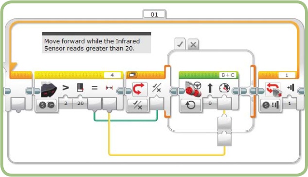
The updated version of the program is shown in Figure 10-3. In addition to removing the Switch block and moving the Move Steering blocks, you’ll need to set the Loop block’s mode to Logic and change the comparison used by the Infrared Sensor block. Because the Loop block exits when the value on the data wire is true, you need the comparison to be Less Than so that the value is false until the TriBot gets near the wall. Notice that the Power parameter of the Move Steering block is still controlled by the Infrared Sensor’s Proximity reading, so the robot should still slow down as it approaches the wall.
Download and run the program; it should behave almost the same as the previous version, moving the TriBot forward quickly at first and then slowing down and stopping close to the wall. This version actually behaves a little better than the previous one because the program exits after stopping. The Switch block version keeps running even though the TriBot stays still.
the loop index
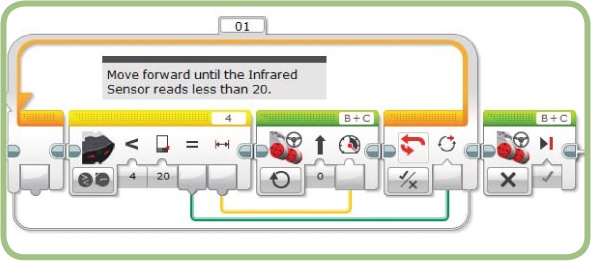
The Loop Index tracks the number of times the loop body has been repeated. The output plug for the Loop Index is on the left side of the Loop block (Figure 10-4). The first time through the loop, this value starts at 0. Each time the program goes back to the beginning of the loop body, the index value increases by one. When the loop finishes, the Loop Index value is one fewer than the number of times the loop completed because it isn’t updated after the last time the body runs.
the LoopIndexTest program
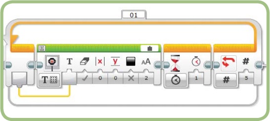
The LoopIndexTest program (shown in Figure 10-5) demonstrates how the Loop Index behaves. The Loop block uses Count mode and is set to repeat five times. Each time through the loop, the Display block shows the Loop Index, and the Wait block adds a short pause to give you time to read the value. When you run this program, the display should show “0”, “1”, “2”, “3”, and “4”.
This program and the two that follow aren’t very interesting to watch (you won’t impress your friends by building a robot that counts to four), but they demonstrate how the Loop block works. When you begin working with a block or feature you haven’t used before, it’s helpful to write small programs like these to explore how they work so you know how to use them in more complex programs.
restarting a loop
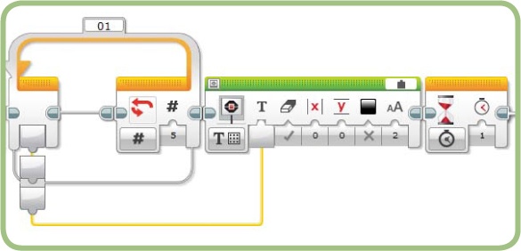
The LoopIndexTest2 program shown in Figure 10-6 shows how a Loop Index works when it’s nested inside another Loop block. The outer Loop block is set to run twice.
The first time the inner loop runs, the display should show “0”, “1”, “2”, “3”, and “4”, just as it did in LoopIndexTest. But what happens the second time the inner loop runs? Will it display “0”, “1”, “2”, “3”, and “4” again or continue counting and show “5”, “6”, “7”, “8”, and “9”?
When you run the program, the display repeats “0”, “1”, “2”, “3”, and “4” twice. This tells you that the Loop Index resets to 0 each time you reach the nested Loop block.

the final loop index value
The LoopIndexTest and LoopIndexTest2 programs use the Loop Index within the loop body. This same value can also be used by blocks that follow the Loop block, as demonstrated by the LoopIndexTest3 program (Figure 10-7). LoopIndexTest3 runs the Loop block five times and then prints the final Loop Index value on the EV3 screen.
This program displays the Loop Index value that’s sent from the data wire after the last run through the loop. This number will be one fewer than the total number of times the loop repeats. (Remember: after the loop runs for the last time, it doesn’t go back to update the Loop Index; it just moves on to the next block.) Because the Loop block is set to run five times, when you run the program, it should print “4” on the display.
the Spiral- LineFinder program
The LineFinder program from Chapter 5 (Figure 10-8) moves the TriBot forward in search of a dark line. That program works fine as long as you start with the robot pointing the right direction, but you can make the program more effective by making the TriBot search in a spiral pattern instead of a simple straight line.
In a rectangular spiral (Figure 10-9), each segment is longer than the previous one, creating an ever-expanding path from a central starting point. The SpiralLineFinder program makes the TriBot follow a rectangular spiral path and stop when the Color Sensor finds a line.
following a spiral
To follow a spiral, the TriBot needs to repeat the following steps: move forward, make a quarter-turn, move forward a little farther than the first move, make a quarter-turn, and so on. By now, you’ve seen that the Loop block is the best way to repeat an action like this. Using Move Steering blocks to move the TriBot forward and make the turn should be familiar as well. The only new idea in this program is changing how far the robot moves forward each time the program goes through the loop by using the Loop Index.
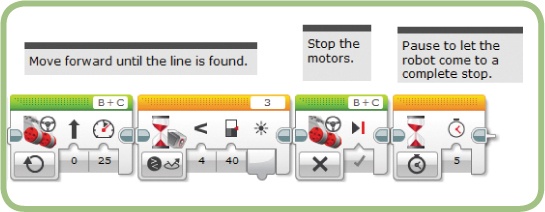
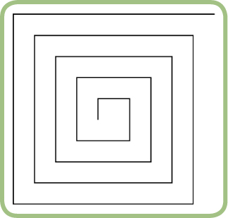

Figure 10-10 shows one way we could make the robot follow a spiral. The first Move Steering block uses On for Rotations mode, in which the number of rotations is set by the Loop Index. Each time through the loop, this block moves the TriBot farther than the last time. The second Move Steering block makes the TriBot spin in place for a quarter-turn.
Note
If you are using the tires in the Education Edition, set the Duration of the second Move Steering block to 160 instead of 210.

Download and run this program and see what happens. You should see the TriBot move in a rectangular spiral pattern—with one possibly unexpected behavior. The first move that the TriBot makes is a turn, rather than a move forward. Why does this happen?
Remember: the Loop Index starts at 0. This means that the first time through the loop, the first Move Steering block is set to move for 0 rotations, so it doesn’t move the robot at all. For this program, it shouldn’t matter which direction the robot is pointing in at the start, so having it turn once before moving forward shouldn’t cause a problem. If you want to change this behavior, you can use a Math block to add 1 to the Loop Index before passing the value to the Move Steering block.
For our SpiralLineFollower program, we’ll do things a bit differently so that the program can constantly check for a line while it’s moving forward. We’ll still use the Loop Index to control how far the robot moves forward, but we’ll pass that value to a Loop block, as you’ll see in a moment.
detecting a line while moving in a spiral
The LineFinder program (shown earlier in Figure 10-8) uses a Wait block in Color Sensor-Reflected Light Intensity mode to detect the line, while a Move Steering block in On mode keeps the robot moving forward. The SpiralLineFollower can’t simply use a Move Steering block in On mode, however, because we want the robot to move in a more sophisticated pattern.
We’ll use a Switch block inside a Loop block to check the Color Sensor while the robot is moving forward and decide when to stop the motor. Start by adding the blocks in Figure 10-11. The first block resets the Rotation Sensor for Motor B to 0. Then the Move Steering block in On mode starts the robot moving, and the Loop block keeps the motors running until the Rotation Sensor reaches the Loop Index. So if the Loop Index value is 2, the robot moves forward until motor B completes two rotations. After the Loop block, a Move Steering block makes the robot turn.
At this point, the program should make the robot move in a spiral, just like our earlier program did in Figure 10-10. This time, however, the Loop block gives us a place to put a Switch block to check the Color Sensor. Be sure to test whether the program works as expected before adding the rest of the code.
Next, we need to add a Switch block inside the Loop block. The Switch block checks the Color Sensor and stops the motors if the reflected light reading is below a threshold (meaning that the robot detected a line). To stop the program when it detects a line, we’ll use a Loop Interrupt block to exit the outer loop.
Figure 10-12 shows the Switch block that needs to be added to the program. The Switch block uses the same Threshold value as the Wait block in the original program. When the condition is true, the motors stop and the loops exit. The name of the outer Loop block is set to 02, and the Loop Interrupt block is configured to match.


When you run the program, the TriBot should move in a rectangular spiral pattern until it finds a dark line, at which point the TriBot stops and the program ends. Experiment with different values for the speed, turning block duration, and Switch block threshold to find the values that give the best results for your test area.
using the gyro sensor for better turns
As the TriBot searches in the spiral pattern, it makes many turns, but it’s impossible to make the TriBot turn exactly a quarter-circle each time. You can (and should) experiment with different values for the duration to get as close as you can to a 90-degree turn, but the movements are not perfectly repeatable, and there are too many other factors that affect how a robot moves (such as battery level, smoothness of the floor, dog hair on the wheels, and so on). Each time the TriBot turns a corner, there is a small amount of error, and as the program runs, these errors add up. After running for a while, you should notice that the rectangle of the spiral starts tilting a little to one side.
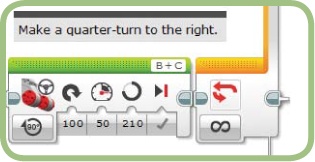
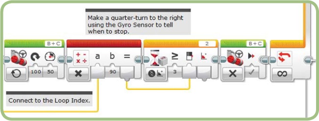
If you have a Gyro Sensor (from the Education Edition, or if you purchased one separately), you can use it to eliminate some of the error. The key is to use the Gyro Sensor to tell when the TriBot reaches increments of 90 degrees as it turns, instead of trying to make the robot turn precisely 90 degrees each time. Figure 10-13 shows the Move Steering block that performs the turn in our original program. Figure 10-14 shows the replacement blocks that perform the same operation using the Gyro Sensor.
The first of the new blocks starts the TriBot turning using On mode so that the program can continue running other blocks while the robot is moving. Each time through the loop, the TriBot should turn 90 degrees. The Math block multiplies the Loop Index by 90 to calculate the Threshold value used by the Wait block. The Wait block uses Gyro Sensor Compare Angle mode to tell when the robot has moved far enough. So when the Loop Index is 1, the robot turns until the Gyro Sensor measures 90 degrees. When the Loop Index is 2, the robot turns until the Gyro Sensor measures a total of 90 × 2, or 180 degrees. This amounts to another 90-degree turn, as the Gyro Sensor measurement isn’t reset anywhere. The final block in the sequence stops the motors.
Download and test the program, and you should find that the path that the TriBot follows doesn’t tilt to one side after the program has been running for a while. In this version, each turn the TriBot makes is not necessarily more accurate than the version that uses the single Move Steering block. The robot might still turn a little past 90 degrees on each turn. The difference with this version is that the errors from each turn don’t accumulate. The second time the robot turns, the program turns the robot until the Gyro Sensor reads 180, regardless of any errors from the previous turn.
You might also notice that the robot now moves forward first, rather than turning first. This is again because the Loop Index starts at 0. This means that the first time through the loop, the robot only turns until the Gyro Sensor reading is greater than or equal to 0, so the turn stops immediately.
further exploration
Try these activities for some more practice with Loop blocks and data wires:
Try making the TriBot follow a circular spiral rather than a rectangular one. You’ll need to adjust the Steering parameter each time through the loop, starting near 100 and then gradually decreasing to make the spiral slowly increase in size.
Use the Loop block to count button presses from the Infrared Remote. You only need a Wait block set to wait for either of two buttons—say, button 1 and button 2. If button 1 is pressed, the loop should repeat, and if button 2 is pressed, the loop should exit. When the loop exits, the Loop Index will match the number of times button 1 was pressed. Hint: You’ll actually need two Wait blocks; the first waits for a button to be pressed, and the second waits for the button state to change. Without the second Wait block, the loop repeats several times for each button press.
With the code from the last challenge, use the number of button presses to set a parameter later in the program. For example, you could use this technique to set the power level of a Move Steering block in order to test a program at different speeds. At the beginning of the program, add code to count the number of button presses and then use the number of presses times 10 as the motor speed.
conclusion
The Loop block can use data wires for both the Loop Index and the loop condition. In this chapter, you modified the GentleStop program to use information from the Infrared Sensor block to control when the loop exits. You’ll use a data wire to set the loop condition again in Chapter 13, where you’ll learn how to combine conditions from multiple sensors.
Once you get used to the Loop Index starting at 0, it’s easy to use it to control blocks in the loop body. The SpiralLineFinder program uses the Loop Index to control the Duration of the MoveSteering block, which makes the TriBot follow a spiral pattern. The Loop Index can be used anytime you want a block’s setting to increase or decrease each time through the loop.