Chapter 9. data wires and the switch block
You can use the Switch block to make decisions about which blocks to run by choosing between two or more alternatives. For example, the WallFollower program in Chapter 7 uses a Switch block that reads the Infrared Sensor and decides whether to move the TriBot toward or away from the wall. In this chapter, you’ll learn how to use the Switch block to make decisions based on a value supplied by a data wire. You’ll also learn how to pass data between the blocks inside the Switch block and the ones that come before or after the Switch block.
the switch block’s value modes
Up until now, you’ve used the Switch block to take a sensor measurement and make a decision based on that measurement. The Switch block can also make a decision based on a value supplied by a data wire. The Text, Logic, and Numeric modes (Figure 9-1) let you create cases to match different possible values passed in to the Switch block from a data wire. The only difference between these three modes is the data type of the value used.
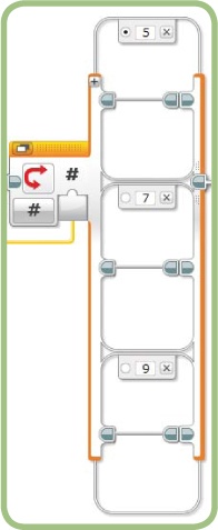
In each of these modes, the Switch block will have a single parameter, which is usually supplied by a data wire. When the block runs, it will choose which case to use based on the value from the data wire. For example, Figure 9-2 shows a Switch block in Numeric mode, with cases for the values 5, 7, and 9. When this block runs, it looks at the value on the data wire. If the value is 5, it chooses the top case; if the value is 7, it chooses the middle case; and if the value is 9, it chooses the bottom case. For other values, the top case is used because it’s marked as the default.

The values in Numeric mode must be integers (whole numbers). For example, if you type in 5.25 to identify a case, the value will be changed to 5. When the Switch block runs, it takes the number on the data wire and rounds it down to the nearest whole number. So in the example above, the middle case will match any value between 7 and 8, including 7 but not including 8.
Text mode works the same way as Numeric mode, except that the values you enter for each case are letters or words instead of numbers. For Numeric or Text mode, you can create as many unique cases as you need. There are only two Logic values, True and False, so Logic mode always has exactly two cases—no more and no less.
rewriting the GentleStop program
Recall that the GentleStop program makes the TriBot slow down and gently stop as it approaches and bumps into a wall. In our first version of the program, the robot stops when the Touch Sensor is pressed, but we could improve the program by making the motors stop when the robot is very close to the wall, before the Touch Sensor is bumped. In this section, you’ll rewrite the GentleStop program to do just that, using the output from the Infrared Sensor block as the trigger for a Switch block.
Note
For the Education Edition, use the Ultrasonic Sensor and Ultrasonic Sensor block in place of the Infrared Sensor and block. The program works equally well with either sensor.

We’ll start by making the TriBot move forward with the Power set to 75 and then stop when the reading from the Infrared Sensor is less than 20. Then we’ll add a data wire so that the Infrared Sensor block controls the Power parameter, as in the original program. This makes the robot move forward (with a Power parameter matching its distance to the wall) until the Infrared Sensor measures a distance of 20 or less. At this point, the robot stops.
Example 9-1 shows the pseudocode for the program, which keeps the TriBot moving forward until the Infrared Sensor reads less than 20, at which point the motors are stopped:
begin loop
read the value from the Infrared Sensor
if the distance > 20 then
move forward, use the Infrared Sensor measurement
for the Power parameter
else
stop moving
end if
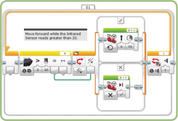
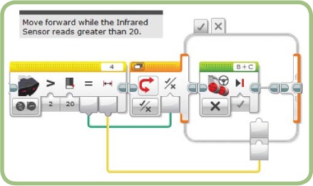
loop until the Touch Sensor is pressedStart by adding and configuring the blocks as shown in Figure 9-3. The Infrared Sensor block uses the Compare - Proximity mode to read the sensor and compare the proximity reading to the Threshold value to determine if it’s greater than 20. The result of this comparison is a Logic value, so set the Switch block to Logic mode to make its decision based on this value. The comparison result is passed to the Switch block using a data wire connected to the Infrared Sensor block’s Compare Result block output. If the value is true, meaning the distance to the wall is greater than 20, the Switch block executes the Move Steering block on the upper case, moving the robot forward. If the distance is 20 or less, the Switch block uses the Move Steering block on the lower case, and the robot stops moving.
Note
For the Ultrasonic Sensor block, select the Measure - Distance Centimeters mode, and set the Threshold value to 15.
Next, we connect another data wire to one of the cases in the Switch block, so we can use the Proximity measurement to control the Power parameter.
passing data into a switch block
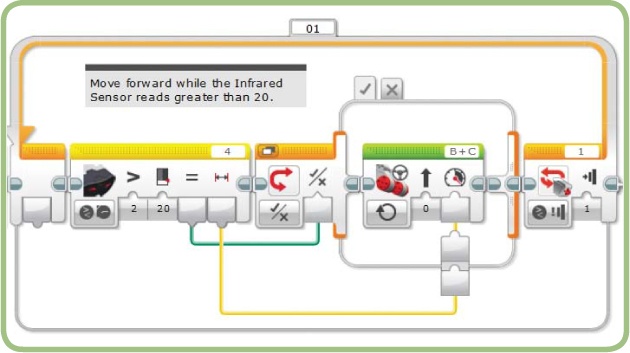
Now we’re going to use a data wire to make the TriBot’s speed depend on its distance from the wall. To connect a data wire from outside the Switch block to a case inside the Switch block, you must put the Switch block in Tabbed View by clicking the Flat/Tabbed View button. When the Switch block is in Tabbed View, you can draw a data wire between the Infrared Sensor block’s Proximity output and the Motor Steering block’s Power input, as shown in Figure 9-4.
When you drag the data wire across the Switch block’s boundary, two block input boxes—called a tunnel—are created: one outside the boundary and one inside. The block input appears on the inside of the Switch block for each tab, and you can choose whether or not to use it in each case. For the Gentle-Stop program, the proximity reading is not used in the case that stops the motor (Figure 9-5), so the block input remains unconnected there.
When you run this version of the program, it should act like the original except that the TriBot should stop the motors when it gets close to the wall instead of bumping into it. One other difference is that the original program ended when the robot hit the wall and pressed the Touch Sensor. In this version, the program keeps running after the robot has stopped moving because the Touch Sensor never gets pressed. We’ll address this issue in the next chapter.
advantages of using a sensor block
In this version of the GentleStop program, we used an Infrared Sensor block to take a measurement, compare it to a threshold, and pass the result to the Switch block instead of using just a Switch block in Infrared Sensor-Compare-Proximity mode to make the measurement. There are several advantages to using a Sensor block with data wires like this rather than just using a Switch block:
A Sensor block gives you access to the sensor reading as well as the result of the comparison. We just took advantage of this in the GentleStop program, where we used the Proximity value to control the Move block’s Power parameter, in addition to using the Comparison Result to stop the robot.
You may want to use a condition that’s more complex than a greater than or less than comparison. Using data wires and the Math, Logic, and Comparison blocks (covered in Chapter 13), you can test for just about any condition you can think of.
The value used by the Switch block can also be passed to other blocks in the program and used to control other behavior.
passing data out of a switch block
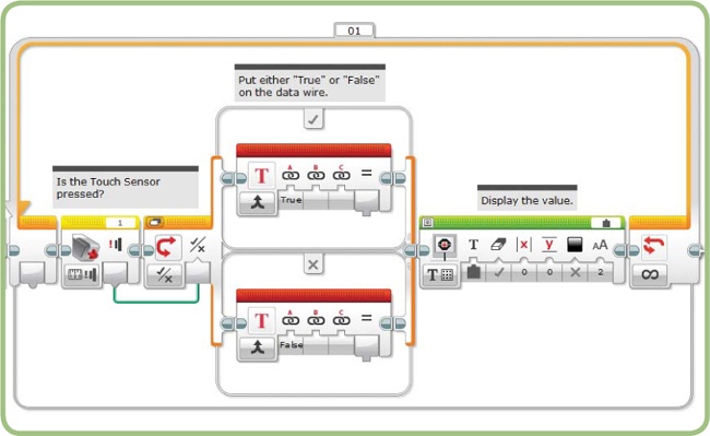
Now let’s build the LogicToText program shown in Figure 9-6 so we can see a simple example of passing data out of a Switch block. This program reads the state of the Touch Sensor and writes “True” on the display if the button is pressed and “False” if it’s not. Both cases of the Switch block contain a Text block with an output plug connected to the Display block. Note that the Text blocks in both cases need to be connected to the Display block.
To build this program, start by configuring the blocks as shown in Figure 9-7. The Touch Sensor block uses the default Measure State mode, and the result is used as the trigger value for the Switch block. The Text block on the Switch block’s upper case generates the text “True”, and the one on the lower case generates “False”. To show the text, set the Display block’s mode to Text Grid, and select Wired in the box where the text normally goes.
Now connect the output from the Text blocks to the Display block by following these steps:
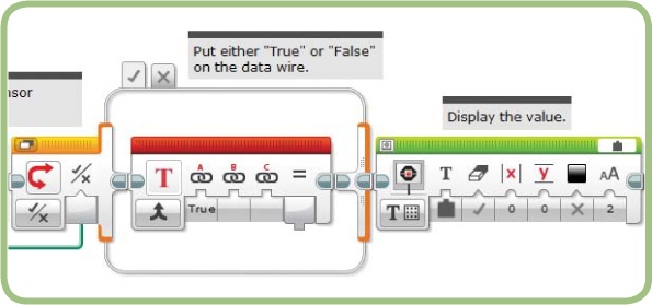
Click the Flat/Tabbed View button of the Switch block. The Switch and Display blocks should look like Figure 9-8.
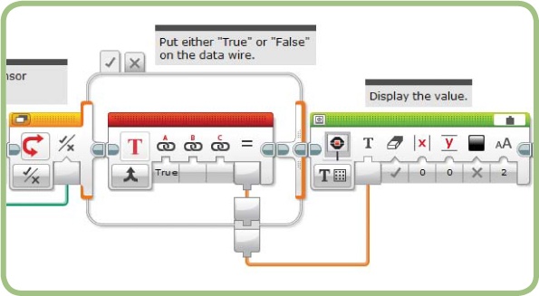
Draw a data wire from the Text block’s Result output to the Display block’s Text input (Figure 9-9). Notice that two block output boxes are created where the data wire crosses the Switch block boundary.
Click the X tab at the top of the Switch block to display the other case.
Connect the Text block’s Result to the block output box on the boundary of the Switch block. This part of the program should now look like Figure 9-10.
When the Switch block runs, it uses only one of the tabs (either the true case or the false case), and the corresponding output of the Text block is sent to the Display block. Try running the program; you should see the display print “True” when the Touch Sensor button is pressed and “False” when it’s released.


simplifying the LineFollower program
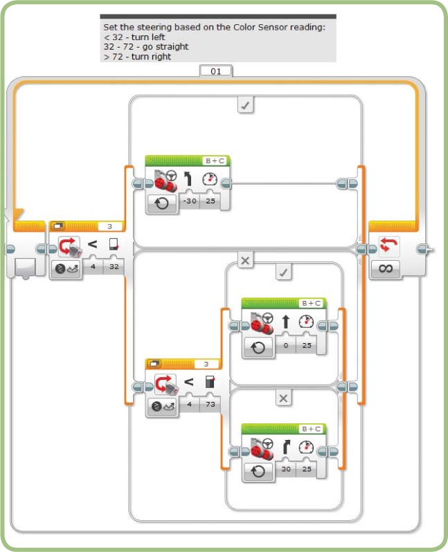
The LineFollower program from Chapter 6 (see Figure 9-11) uses nested Switch blocks to choose between three Move Steering blocks. One block turns the robot to the left, one moves the robot straight, and one turns the robot to the right.
A Switch block in Sensor Comparison mode can only have two cases; either the sensor reading meets the criteria or it doesn’t. To choose from three cases (as in our program above), you need two nested Switch blocks. If you wanted to choose among five cases, you would need four nested Switch blocks. You can see how this can get out of hand quickly.
Because a Switch block in Numeric mode can have any number of cases, you can often replace a group of nested Switch blocks that use a single sensor mode with one Switch block in Numeric mode. Numeric mode lets you add as many cases as you want, without having to nest. At the same time, however, you don’t want to create a different case for each possible sensor reading (from 1 to 100, say). The key is to group all the expected sensor readings into a small set of numbers. This approach, often used in programming, is called binning, which uses a little arithmetic to map the sensor reading ranges you are interested in to a group of small numbers. It’s called binning because it takes a large group of numbers and puts related values into groups or bins. In this version of the LineFollower program, you’ll take the range of expected sensor values and put them into three bins: one set of values that causes the robot to turn to the left, one set that causes the robot to go straight, and one set that causes the robot to turn to the right.
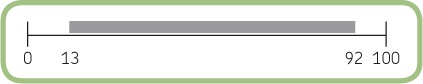
To calculate our bins, we need three numbers: the lowest and highest value you expect from the sensor, and the number of bins. Recall from Chapter 6 that testing the Color Sensor on the line and background revealed that the smallest reading I can expect is 13 and the largest is 92. Figure 9-12 shows a graphical representation of this range of values, out of the possible values from the sensor. When the LineFollower program runs, I expect that all the readings from the Color Sensor will fall in the area marked by the gray box.
The first step in the binning process is to slide the range to the left so that it starts at 0, as shown in Figure 9-13. In the program, you can do this by subtracting 13 (the lowest expected value) from the sensor reading. Once you do that, you’ll have a value in the range of 0 to 79. The range of values has to start at 0 in order for the next step in the process to work correctly.

The second step is to divide the range into three bins (Figure 9-14). I’ve numbered the bins 0, 1, and 2 because that will make the math work out easier. The size of the total range of values I expect is 79, so we can divide that by 3 to find out the size of each bin: 79 divided by 3 is 26.33333, but I find it easier to deal in whole numbers than decimals, and the boundary between each bin doesn’t have to be exact, so I’ll round up to 27 here instead. To go from a sensor value to the bin number, all you need to do is subtract 13 to get a value in the range of 0 to 79, and then divide by 27. The result of the division is a decimal number, but when you pass the result to the Switch block, it rounds the value down to the next lowest whole number, which gives us the bin number. For example, if you divide 60 by 27, you get 2.22, which the Switch block rounds down to 2 to give you the right bin number.

The new version of the program contains one Switch block with three cases—one for each Move Steering block. The value for each case corresponds to the bin numbers (0, 1, and 2). The program uses the binning process to convert the Color Sensor reading into one of the three cases by first subtracting 13 and then dividing by 27 (and then rounding down the result). You can write this as a formula:
Case number = (Sensor reading – 13) / 27
Table 9-1 shows the range of values for each case and the associated program behavior. The ranges shown here are a little different from those used in Chapter 6 because we used a different method for determining the limits of each range.
Color Sensor Reading | Case Number | program Behavior |
13-39 | 0 | Turn left |
40-66 | 1 | Go straight |
67-92 | 2 | Turn right |
Now you’re ready to rewrite the program. The first part of the program uses the Color Sensor block to read the sensor and two Math blocks to subtract 13 and divide by 27 (Figure 9-15). The Color Sensor block uses Measure-Reflected Light Intensity mode, as in the original program.
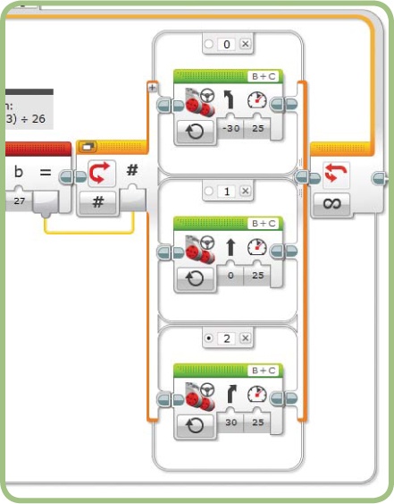
The second part of the program uses a Switch block in Numeric mode to match the bin number to the appropriate Move Steering block (Figure 9-16). I’ve kept the Switch block in Flat View so you can see all three cases; in your own program you may want to use Tabbed View to conserve space. The bottom case (the one for bin 2) is selected as the default so that the program acts reasonably if the sensor value is above 92.
What happens if the sensor value is less than 13? In that case, the result from the second Math block is a small negative number, which is rounded to 0 by the Switch block, and the correct case is selected. It turns out that as long as the sensor reading is within half a bin-width (27 / 2, or 13.5, in this example) of the lowest expected value, the program works correctly. In this case, all the possible values below our lowest value (0-13) fall within half a bin width, so the binning process works even for those readings, but keep this in mind if you use a binning technique with different ranges in other programs. Selecting the right values for the highest and lowest expected sensor readings is very important. You don’t want to end up with unexpected behavior in cases where a reading is outside that range.

When you run the program, it should behave much like the previous version. Essentially, you simplified the Switch block by adding the complexity of the Math blocks. On balance, the program is now more elegant and easier to enhance (such as with the following challenge).
further exploration
Here are some activities you can try that involve using data wires with the Switch block:
Experiment with drawing data wires into and out of a Switch block. Try the following:
Put the Switch block in Flat View and try to draw a data wire into and out of the block.
Put the Switch block in Tabbed View and draw a wire between a block outside and a block inside the Switch block. Then click the Flat/Tabbed View button.
Draw a few data wires into the Switch block. Practice moving the data wires to become familiar with how the data wires can be arranged both inside and outside the Switch block. In addition to moving the data wires, you can drag the tunnels to the place where the wire crosses into or out of the Switch block.
Change the SoundMachine program so that it displays the volume as “Soft”, “Medium”, “Loud”, or “Very Loud” instead of a percentage. Choose the text to display by dividing the volume into four ranges using the binning process.
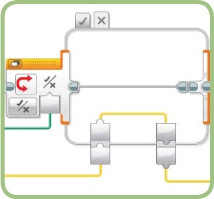
You can use a Switch block with data wires to place a limit on a value. For example, a Sensor block can compare a measurement with a Threshold value and pass the result to a Switch block in Logic mode. One case of the Switch block would pass the value from the Sensor block through the Switch block, and out through a data wire, with no blocks in between (Figure 9-17). The other case would pass on the maximum value instead.
Write a program that moves the TriBot using the ambient light level for the Power parameter of a Move Steering block, but limit the value to a maximum of 75.
conclusion
Using a data wire to supply the input to a Switch block gives you a lot of flexibility in the types of decisions your programs can make. Using a Sensor block, you can perform a comparison outside the Switch block, which allows you to make more complex decisions than the Switch block alone supports. Data wires also allow you to pass data between the blocks inside the Switch block and those before or after, so you can easily customize each choice or make decisions that affect the rest of the program.
Using a Number or Text value as input, you can make the Switch block choose from more than two possible alternatives. This allows your program to more easily make complex decisions and can help avoid deeply nested Switch blocks. The binning process used in the LineFollower program is a very common method for accomplishing this.