
Chapter 8
Local Filestores
This chapter describes the organization and management of data on storage media. 4.4BSD provides three different filestore managers: the traditional Berkeley Fast Filesystem (FFS), the recently added Log-Structured Filesystem (LFS), and the Memory-based Filesystem (MFS) that uses much of the FFS code base. The FFS filestore was designed on the assumption that buffer caches would be small and thus that files would need to be read often. It tries to place files likely to be accessed together in the same general location on the disk. It is described in Section 8.2. The LFS filestore was designed for fast machines with large buffer caches. It assumes that writing data to disk is the bottleneck, and it tries to avoid seeking by writing all data together in the order in which they were created. It assumes that active files will remain in the buffer cache, so is little concerned with the time that it takes to retrieve files from the filestore. It is described in Section 8.3. The MFS filestore was designed as a fast-access repository for transient data. It is used primarily to back the /tmp filesystem. It is described in Section 8.4.
8.1 Overview of the Filestore
The vnode operations defined for doing the datastore filesystem operations are shown in Table 8.1 (on page 266). These operators are fewer and semantically simpler than are those used for managing the name space.
There are two operators for allocating and freeing objects. The valloc operator creates a new object. The identity of the object is a number returned by the operator. The mapping of this number to a name is the responsibility of the name-space code. An object is freed by the vfree operator. The object to be freed is identified by only its number.
The attributes of an object are changed by the update operator. This layer does no interpretation of these attributes; they are simply fixed-size auxiliary data stored outside the main data area of the object. They are typically file attributes, such as the owner, group, permissions, and so on.
Table 8.1 Datastore filesystem operations.
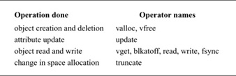
There are five operators for manipulating existing objects. The vget operator retrieves an existing object from the filestore. The object is identified by its number and must have been created previously by valloc. The read operator copies data from an object to a location described by a uio structure. The blkatoff operator is similar to the read operator, except that the blkatoff operator simply returns a pointer to a kernel memory buffer with the requested data, instead of copying the data. This operator is designed to increase the efficiency of operations where the name-space code interprets the contents of an object (i.e., directories), instead of just returning the contents to a user process. The write operator copies data to an object from a location described by a uio structure. The fsync operator requests that all data associated with the object be moved to stable storage (usually by their all being written to disk). There is no need for an analog of blkatoff for writing, as the kernel can simply modify a buffer that it received from blkatoff, mark that buffer as dirty, and then do an fsync operation to have the buffer written back.
The final datastore operation is truncate. This operation changes the amount of space associated with an object. Historically, it could be used only to decrease the size of an object. In 4.4BSD, it can be used both to increase and to decrease the size of an object.
Each disk drive has one or more subdivisions, or partitions. Each such partition can contain only one filestore, and a filestore never spans multiple partitions.
The filestore is responsible for the management of the space within its disk partition. Within that space, its responsibility is the creation, storage, retrieval, and removal of files. It operates in a flat name space. When asked to create a new file, it allocates an inode for that file and returns the assigned number. The naming, access control, locking, and attribute manipulation for the file are all handled by the hierarchical filesystem-management layer above the filestore.
The filestore also handles the allocation of new blocks to files as the latter grow. Simple filesystem implementations, such as those used by early microcomputer systems, allocate files contiguously, one after the next, until the files reach the end of the disk. As files are removed, holes occur. To reuse the freed space, the system must compact the disk to move all the free space to the end. Files can be created only one at a time; for the size of a file other than the final one on the disk to be increased, the file must be copied to the end, then expanded.
As we saw in Section 7.2, each file in a filestore is described by an inode; the locations of its data blocks are given by the block pointers in its inode. Although the filestore may cluster the blocks of a file to improve I/O performance, the inode can reference blocks scattered anywhere throughout the partition. Thus, multiple files can be written simultaneously, and all the disk space can be used without the need for compaction.
The filestore implementation converts from the user abstraction of a file as an array of bytes to the structure imposed by the underlying physical medium. Consider a typical medium of a magnetic disk with fixed-sized sectoring. Although the user may wish to write a single byte to a file, the disk supports reading and writing only in multiples of sectors. Here, the system must read in the sector containing the byte to be modified, replace the affected byte, and write the sector back to the disk. This operation—converting random access to an array of bytes to reads and writes of disk sectors—is called block I/O.
First, the system breaks the user’s request into a set of operations to be done on logical blocks of the file. Logical blocks describe block-sized pieces of a file. The system calculates the logical blocks by dividing the array of bytes into file-store-sized pieces. Thus, if a filestore’s block size is 8192 bytes, then logical block 0 would contain bytes 0 to 8191, logical block 1 would contain bytes 8192 to 16,383, and so on.
The data in each logical block are stored in a physical block on the disk. A physical block is the location on the disk to which the system maps a logical block. A physical disk block is constructed from one or more contiguous sectors. For a disk with 512-byte sectors, an 8192-byte filestore block would be built up from 16 contiguous sectors. Although the contents of a logical block are contiguous on disk, the logical blocks of the file do not need to be laid out contiguously. The data structure used by the system to convert from logical blocks to physical blocks was described in Section 7.2.
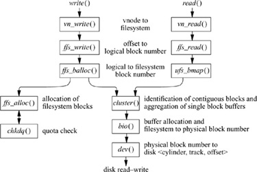
Figure 8.1 (on page 268) shows the flow of information and work required to access the file on the disk. The abstraction shown to the user is an array of bytes. These bytes are collectively described by a file descriptor that refers to some location in the array. The user can request a write operation on the file by presenting the system with a pointer to a buffer, with a request for some number of bytes to be written. As shown in Fig. 8.1, the requested data do not need to be aligned with the beginning or end of a logical block. Further, the size of the request is not constrained to a single logical block. In the example shown, the user has requested data to be written to parts of logical blocks 1 and 2. Since the disk can transfer data only in multiples of sectors, the filestore must first arrange to read in the data for any part of the block that is to be left unchanged. The system must arrange an intermediate staging area for the transfer. This staging is done through one or more system buffers, as described in Section 6.6.
In our example, the user wishes to modify data in logical blocks 1 and 2. The operation iterates over five steps:
Figure 8.1 The block I/O system.
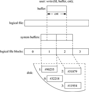
1. Allocate a buffer.
2. Determine the location of the corresponding physical block on the disk.
3. Request the disk controller to read the contents of the physical block into the system buffer and wait for the transfer to complete.
4. Do a memory-to-memory copy from the beginning of the user’s I/O buffer to the appropriate portion of the system buffer.
5. Write the block to the disk and continue without waiting for the transfer to complete.
If the user’s request is incomplete, the process is repeated with the next logical block of the file. In our example, the system fetches logical block 2 of the file and is able to complete the user’s request. Had an entire block been written, the system could have skipped step 3 and have simply written the data to the disk without first reading in the old contents. This incremental filling of the write request is transparent to the user’s process because that process is blocked from running during the entire procedure. The filling is transparent to other processes; because the inode is locked during the process, any attempted access by any other process will be blocked until the write has completed.
8.2 The Berkeley Fast Filesystem
A traditional UNIX filesystem is described by its superblock, which contains the basic parameters of the filesystem. These parameters include the number of data blocks in the filesystem, a count of the maximum number of files, and a pointer to the free list, which is a list of all the free blocks in the filesystem.
A 150-Mbyte traditional UNIX filesystem consists of 4 Mbyte of inodes followed by 146 Mbyte of data. That organization segregates the inode information from the data; thus, accessing a file normally incurs a long seek from the file’s inode to its data. Files in a single directory typically are not allocated consecutive slots in the 4 Mbyte of inodes, causing many nonconsecutive disk blocks to be read when many inodes in a single directory are accessed.
The allocation of data blocks to files also is suboptimal. The traditional filesystem implementation uses a 512-byte physical block size. But the next sequential data block often is not on the same cylinder, so seeks between 512-byte data transfers are required frequently. This combination of small block size and scattered placement severely limits filesystem throughput.
The first work on the UNIX filesystem at Berkeley attempted to improve both the reliability and the throughput of the filesystem. The developers improved reliability by staging modifications to critical filesystem information so that the modifications could be either completed or repaired cleanly by a program after a crash [McKusick & Kowalski, 1994]. Doubling the block size of the filesystem improved the performance of the 4.0BSD filesystem by a factor of more than 2 when compared with the 3BSD filesystem. This doubling caused each disk transfer to access twice as many data blocks and eliminated the need for indirect blocks for many files. In the remainder of this section, we shall refer to the filesystem with these changes as the old filesystem.
The performance improvement in the old filesystem gave a strong indication that increasing the block size was a good method for improving throughput. Although the throughput had doubled, the old filesystem was still using only about 4 percent of the maximum disk throughput. The main problem was that the order of blocks on the free list quickly became scrambled, as files were created and removed. Eventually, the free-list order became entirely random, causing files to have their blocks allocated randomly over the disk. This randomness forced a seek before every block access. Although the old filesystem provided transfer rates of up to 175 Kbyte per second when it was first created, the scrambling of the free list caused this rate to deteriorate to an average of 30 Kbyte per second after a few weeks of moderate use. There was no way of restoring the performance of an old filesystem except to recreate the system.
Organization of the Berkeley Fast Filesystem
The first version of the current BSD filesystem appeared in 4.2BSD [McKusick et al, 1984]. In the 4.4BSD filesystem organization (as in the old filesystem organization), each disk drive contains one or more filesystems. A 4.4BSD filesystem is described by its superblock, located at the beginning of the filesystem’s disk partition. Because the superblock contains critical data, it is replicated to protect against catastrophic loss. This replication is done when the filesystem is created; since the superblock data do not change, the copies do not need to be referenced unless a disk failure causes the default superblock to be corrupted.
So that files as large as 232 bytes can be created with only two levels of indirection, the minimum size of a filesystem block is 4096 bytes. The block size can be any power of 2 greater than or equal to 4096. The block size is recorded in the filesystem’s superblock, so it is possible for filesystems with different block sizes to be accessed simultaneously on the same system. The block size must be selected at the time that the filesystem is created; it cannot be changed subsequently without the filesystem being rebuilt.
The BSD filesystem organization divides a disk partition into one or more areas, each of which is called a cylinder group. Figure 8.2 shows a set of cylinder groups, each comprising one or more consecutive cylinders on a disk. Each cylinder group contains bookkeeping information that includes a redundant copy of the superblock, space for inodes, a bitmap describing available blocks in the cylinder group, and summary information describing the usage of data blocks within the cylinder group. The bitmap of available blocks in the cylinder group replaces the traditional filesystem’s free list. For each cylinder group, a static number of inodes is allocated at filesystem-creation time. The default policy is to allocate one inode for each 2048 bytes of space in the cylinder group, with the expectation that this amount will be far more than will ever be needed. The default may be changed at the time that the filesystem is created.
Figure 8.2 Layout of cylinder groups.
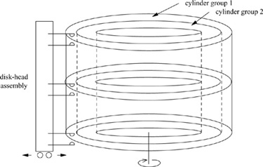
The rationale for using cylinder groups is to create clusters of inodes that are spread over the disk close to the blocks that they reference, instead of them all being located at the beginning of the disk. The filesystem attempts to allocate file blocks close to the inodes that describe them to avoid long seeks between getting the inode and getting its associated data. Also, when the inodes are spread out, there is less chance of losing all of them in a single disk failure.
All the bookkeeping information could be placed at the beginning of each cylinder group. If this approach were used, however, all the redundant information would be on the same platter of a disk. A single hardware failure could then destroy all copies of the superblock. Thus, the bookkeeping information begins at a varying offset from the beginning of the cylinder group. The offset for each successive cylinder group is calculated to be about one track farther from the beginning than in the preceding cylinder group. In this way, the redundant information spirals down into the pack, so that any single track, cylinder, or platter can be lost without all copies of the superblock also being lost. Except for the first cylinder group, which leaves space for a boot block, the space between the beginning of the cylinder group and the beginning of the cylinder-group information is used for data blocks.
Optimization of Storage Utilization
Data are laid out such that large blocks can be transferred in a single disk operation, greatly increasing filesystem throughput. A file in the new filesystem might be composed of 8192-byte data blocks, as compared to the 1024-byte blocks of the old filesystem; disk accesses would thus transfer up to 8 times as much information per disk transaction. In large files, several blocks can be allocated consecutively, so that even larger data transfers are possible before a seek is required.
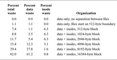
The main problem with larger blocks is that most BSD filesystems contain primarily small files. A uniformly large block size will waste space. Table 8.2 shows the effect of filesystem block size on the amount of wasted space in the filesystem. The measurements used to compute this table were collected from a survey of the Internet conducted in 1993 [Irlam, 1993]. The survey covered 12 million files residing on 1000 filesystems with a total size of 250 Gbyte. The investigators found that the median file size was under 2048 bytes; the average file size was 22 Kbyte. The space wasted is calculated to be the percentage of disk space not containing user data. As the block size increases, the amount of space reserved for inodes decreases, but the amount of unused data space at the end of blocks rises quickly to an intolerable 29.4 percent waste with a minimum allocation of 8192-byte filesystem blocks.
Table 8.2 Amount of space wasted as a function of block size.
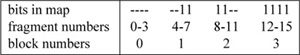
For large blocks to be used without significant waste, small files must be stored more efficiently. To increase space efficiency, the filesystem allows the division of a single filesystem block into one or more fragments. The fragment size is specified at the time that the filesystem is created; each filesystem block optionally can be broken into two, four, or eight fragments, each of which is addressable. The lower bound on the fragment size is constrained by the disk-sector size, which is typically 512 bytes. The block map associated with each cylinder group records the space available in a cylinder group in fragments; to determine whether a block is available, the system examines aligned fragments. Figure 8.3 shows a piece of a block map from a filesystem with 4096-byte blocks and 1024-byte fragments, hereinafter referred to as a 4096/1024 filesystem.
On a 4096/1024 filesystem, a file is represented by zero or more 4096-byte blocks of data, possibly plus a single fragmented block. If the system must fragment a block to obtain space for a small number of data, it makes the remaining fragments of the block available for allocation to other files. As an example, consider an 11000-byte file stored on a 4096/1024 filesystem. This file would use two full-sized blocks and one three-fragment portion of another block. If no block with three aligned fragments were available at the time that the file was created, a full-sized block would be split, yielding the necessary fragments and a single unused fragment. This remaining fragment could be allocated to another file as needed.
Figure 8.3 Example of the layout of blocks and fragments in a 4096/1024 filesystem. Each bit in the map records the status of a fragment; a “-” means that the fragment is in use, whereas a “1” means that the fragment is available for allocation. In this example, fragments 0 through 5, 10, and 11 are in use, whereas fragments 6 through 9 and 12 through 15 are free. Fragments of adjacent blocks cannot be used as a full block, even if they are large enough. In this example, fragments 6 through 9 cannot be allocated as a full block; only fragments 12 through 15 can be coalesced into a full block.
Reading and Writing to a File
Having opened a file, a process can do reads or writes on it. The procedural path through the kernel is shown in Fig. 8.4. If a read is requested, it is channeled through the ffs_read () routine. Ffs_read() is responsible for converting the read into one or more reads of logical file blocks. A logical block request is then handed off to ufs_bmap(). Ufs_bmap() is responsible for converting a logical block number to a physical block number by interpreting the direct and indirect block pointers in an inode. Ffs_read() requests the block I/O system to return a buffer filled with the contents of the disk block. If two or more logically sequential blocks are read from a file, the process is assumed to be reading the file sequentially. Here, ufs_bmap() returns two values: first, the disk address of the requested block; then, the number of contiguous blocks that follow that block on disk. The requested block and the number of contiguous blocks that follow it are passed to the cluster() routine. If the file is being accessed sequentially, the cluster() routine will do a single large I/O on the entire range of sequential blocks. If the file is not being accessed sequentially (as determined by a seek to a different part of the file preceding the read), only the requested block or a subset of the cluster will be read. If the file has had a long series of sequential reads, or if the number of contiguous blocks is small, the system will issue one or more requests for read-ahead blocks in anticipation that the process will soon want those blocks. The details of block clustering are described at the end of this section.
Figure 8.4 Procedural interface to reading and writing.
Each time that a process does a write system call, the system checks to see whether the size of the file has increased. A process may overwrite data in the middle of an existing file, in which case space would usually have been allocated already (unless the file contains a hole in that location). If the file needs to be extended, the request is rounded up to the next fragment size, and only that much space is allocated (see “Allocation Mechanisms” later in this section for the details of space allocation). The write system call is channeled through the ffs_write() routine. Ffs_write() is responsible for converting the write into one or more writes of logical file blocks. A logical block request is then handed off to ffs_balloc(). Ffs_balloc() is responsible for interpreting the direct and indirect block pointers in an inode to find the location for the associated physical block pointer. If a disk block does not already exist, the ffs_alloc() routine is called to request a new block of the appropriate size. After calling chkdq() to ensure that the user has not exceeded their quota, the block is allocated, and the address of the new block is stored in the inode or indirect block. The address of the new or already-existing block is returned. Ffs_write() allocates a buffer to hold the contents of the block. The user’s data are copied into the returned buffer, and the buffer is marked as dirty. If the buffer has been filled completely, it is passed to the cluster() routine. When a maximally sized cluster has been accumulated, a noncontiguous block is allocated, or a seek is done to another part of the file, and the accumulated blocks are grouped together into a single I/O operation that is queued to be written to the disk. If the buffer has not been filled completely, it is not considered immediately for writing. Rather, the buffer is held in the expectation that the process will soon want to add more data to it. It is not released until it is needed for some other block—that is, until it has reached the head of the free list, or until a user process does a sync system call. There is normally a user process called update that does a sync every 30 seconds.
Repeated small write requests may expand the file one fragment at a time. The problem with expanding a file one fragment at a time is that data may be copied many times as a fragmented block expands to a full block. Fragment reallocation can be minimized if the user process writes a full block at a time, except for a partial block at the end of the file. Since filesystems with different block sizes may reside on the same system, the filesystem interface provides application programs with the optimal size for a read or write. This facility is used by the standard I/O library that many application programs use, and by certain system utilities, such as archivers and loaders, that do their own I/O management.
If the layout policies (described at the end of this section) are to be effective, a filesystem cannot be kept completely full. A parameter, termed the free-space reserve, gives the minimum percentage of filesystem blocks that should be kept free. If the number of free blocks drops below this level, only the superuser is allowed to allocate blocks. This parameter can be changed any time that the filesystem is unmounted. When the number of free blocks approaches zero, the filesystem throughput tends to be cut in half because the filesystem is unable to localize blocks in a file. If a filesystem’s throughput drops because of overfilling, it can be restored by removal of files until the amount of free space once again reaches the minimum acceptable level. Users can restore locality to get faster access rates for files created during periods of little free space by copying the file to a new one and removing the original one when enough space is available.
Filesystem Parameterization
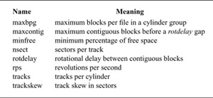
Except for the initial creation of the free list, the old filesystem ignores the parameters of the underlying hardware. It has no information about either the physical characteristics of the mass-storage device or the hardware that interacts with the filesystem. A goal of the new filesystem is to parameterize the processor capabilities and mass-storage characteristics so that blocks can be allocated in an optimum configuration-dependent way. Important parameters include the speed of the processor, the hardware support for mass-storage transfers, and the characteristics of the mass-storage devices. These parameters are summarized in Table 8.3. Disk technology is constantly improving, and a given installation can have several different disk technologies running on a single processor. Each filesystem is parameterized so that it can be adapted to the characteristics of the disk on which it is located.
For mass-storage devices such as disks, the new filesystem tries to allocate a file’s new blocks on the same cylinder and rotationally well positioned. The distance between rotationally optimal blocks varies greatly; optimal blocks can be consecutive or rotationally delayed, depending on system characteristics. For disks attached to a dedicated I/O processor or accessed by a track-caching controller, two consecutive disk blocks often can be accessed without time lost because of an intervening disk revolution. Otherwise, the main processor must field an interrupt and prepare for a new disk transfer. The expected time to service this interrupt and to schedule a new disk transfer depends on the speed of the main processor.
The physical characteristics of each disk include the number of blocks per track and the rate at which the disk spins. The allocation routines use this information to calculate the number of milliseconds required to skip over a block. The characteristics of the processor include the expected time to service an interrupt and to schedule a new disk transfer. Given a block allocated to a file, the allocation routines calculate the number of blocks to skip over such that the next block in the file will come into position under the disk head in the expected amount of time that it takes to start a new disk-transfer operation. For sequential access to large numbers of data, this strategy minimizes the amount of time spent waiting for the disk to position itself.
Table 8.3 Important parameters maintained by the filesystem.
The parameter that defines the minimum number of milliseconds between the completion of a data transfer and the initiation of another data transfer on the same cylinder can be changed at any time. If a filesystem is parameterized to lay out blocks with a rotational separation of 2 milliseconds, and the disk is then moved to a system that has a processor requiring 4 milliseconds to schedule a disk operation, the throughput will drop precipitously because of lost disk revolutions on nearly every block. If the target machine is known, the filesystem can be parameterized for that machine, even though it is initially created on a different processor. Even if the move is not known in advance, the rotational-layout delay can be reconfigured after the disk is moved, so that all further allocation is done based on the characteristics of the new machine.
Layout Policies
The filesystem layout policies are divided into two distinct parts. At the top level are global policies that use summary information to make decisions regarding the placement of new inodes and data blocks. These routines are responsible for deciding the placement of new directories and files. They also calculate rotationally optimal block layouts and decide when to force a long seek to a new cylinder group because there is insufficient space left in the current cylinder group to do reasonable layouts. Below the global-policy routines are the local-allocation routines. These routines use a locally optimal scheme to lay out data blocks. The original intention was to bring out these decisions to user level so that they could be ignored or replaced by user processes. Thus, they are definitely policies, rather than simple mechanisms.
Two methods for improving filesystem performance are to increase the locality of reference to minimize seek latency [Trivedi, 1980], and to improve the layout of data to make larger transfers possible [Nevalainen & Vesterinen, 1977]. The global layout policies try to improve performance by clustering related information. They cannot attempt to localize all data references, but must instead try to spread unrelated data among different cylinder groups. If too much localization is attempted, the local cylinder group may run out of space, forcing further related data to be scattered to nonlocal cylinder groups. Taken to an extreme, total localization can result in a single huge cluster of data resembling the old filesystem. The global policies try to balance the two conflicting goals of localizing data that are concurrently accessed while spreading out unrelated data.
One allocatable resource is inodes. Inodes of files in the same directory frequently are accessed together. For example, the list-directory command, Is, may access the inode for each file in a directory. The inode layout policy tries to place all the inodes of files in a directory in the same cylinder group. To ensure that files are distributed throughout the filesystem, the system uses a different policy to allocate directory inodes. New directories are placed in cylinder groups with a greater-than-average number of free inodes and with the smallest number of directories. The intent of this policy is to allow inode clustering to succeed most of the time. The filesystem allocates inodes within a cylinder group using a next-free strategy. Although this method allocates the inodes randomly within a cylinder group, all the inodes for a particular cylinder group can be accessed with 10 to 20 disk transfers. This allocation strategy puts a small and constant upper bound on the number of disk transfers required to access the inodes for all the files in a directory. In contrast, the old filesystem typically requires one disk transfer to fetch the inode for each file in a directory.
The other major resource is data blocks. Data blocks for a file typically are accessed together. The policy routines try to place data blocks for a file in the same cylinder group, preferably at rotationally optimal positions in the same cylinder. The problem with allocating all the data blocks in the same cylinder group is that large files quickly use up the available space, forcing a spillover to other areas. Further, using all the space causes future allocations for any file in the cylinder group also to spill to other areas. Ideally, none of the cylinder groups should ever become completely full. The heuristic chosen is to redirect block allocation to a different cylinder group after every few Mbyte of allocation. The spillover points are intended to force block allocation to be redirected when any file has used about 25 percent of the data blocks in a cylinder group. In day-today use, the heuristics appear to work well in minimizing the number of completely filled cylinder groups. Although this heuristic appears to benefit small files at the expense of the larger files, it really aids both file sizes. The small files are helped because there are nearly always blocks available in the cylinder group for them to use. The large files benefit because they are able to use rotationally well laid out space and then to move on, leaving behind the blocks scattered around the cylinder group. Although these scattered blocks are fine for small files that need only a block or two, they slow down big files that are best stored on a single large group of blocks that can be read in a few disk revolutions.
The newly chosen cylinder group for block allocation is the next cylinder group that has a greater-than-average number of free blocks left. Although big files tend to be spread out over the disk, several Mbyte of data typically are accessible before a seek to a new cylinder group is necessary. Thus, the time to do one long seek is small compared to the time spent in the new cylinder group doing the I/O.
Allocation Mechanisms
The global-policy routines call local-allocation routines with requests for specific blocks. The local-allocation routines will always allocate the requested block if it is free; otherwise, they will allocate a free block of the requested size that is rotationally closest to the requested block. If the global layout policies had complete information, they could always request unused blocks, and the allocation routines would be reduced to simple bookkeeping. However, maintaining complete information is costly; thus, the global layout policy uses heuristics based on the partial information that is available.
If a requested block is not available, the local allocator uses a four-level allocation strategy:
1. Use the next available block rotationally closest to the requested block on the same cylinder. It is assumed that head-switching time is zero. On disk controllers where this assumption is not valid, the time required to switch between disk platters is incorporated into the rotational layout tables when they are constructed.
2. If no blocks are available on the same cylinder, choose a block within the same cylinder group.
3. If the cylinder group is full, quadratically hash the cylinder-group number to choose another cylinder group in which to look for a free block. Quadratic hash is used because of its speed in finding unused slots in nearly full hash tables [Knuth, 1975]. Filesystems that are parameterized to maintain at least 10 percent free space rarely need to use this strategy. Filesystems used without free space typically have so few free blocks available that almost any allocation is random; the most important characteristic of the strategy used under such conditions is that it be fast.
4. Apply an exhaustive search to all cylinder groups. This search is necessary because the quadratic rehash may not check all cylinder groups.
The task of managing block and fragment allocation is done by ffs_balloc(). If the file is being written and a block pointer is zero or points to a fragment that is too small to hold the additional data, ffs_balloc() calls the allocation routines to obtain a new block. If the file needs to be extended, one of two conditions exists:
1. The file contains no fragmented blocks (and the final block in the file contains insufficient space to hold the new data). If space exists in a block already allocated, the space is filled with new data. If the remainder of the new data consists of more than a full block, a full block is allocated and the first full block of new data is written there. This process is repeated until less than a full block of new data remains. If the remaining new data to be written will fit in less than a full block, a block with the necessary number of fragments is located; otherwise, a full block is located. The remaining new data are written into the located space. However, to avoid excessive copying for slowly growing files, the filesystem allows only direct blocks of files to refer to fragments.
2. The file contains one or more fragments (and the fragments contain insufficient space to hold the new data). If the size of the new data plus the size of the data already in the fragments exceeds the size of a full block, a new block is allocated. The contents of the fragments are copied to the beginning of the block, and the remainder of the block is filled with new data. The process then continues as in step 1. Otherwise, a set of fragments big enough to hold the data is located; if enough of the rest of the current block is free, the filesystem can avoid a copy by using that block. The contents of the existing fragments, appended with the new data, are written into the allocated space.
Figure 8.5 Procedural interface to block allocation.
Ffs_balloc() is also responsible for allocating blocks to hold indirect pointers. It must also deal with the special case in which a process seeks past the end of a file and begins writing. Because of the constraint that only the final block of a file may be a fragment, ffs_balloc() must first ensure that any previous fragment has been upgraded to a full-sized block.
On completing a successful allocation, the allocation routines return the block or fragment number to be used; ffs_balloc() then updates the appropriate block pointer in the inode. Having allocated a block, the system is ready to allocate a buffer to hold the block’s contents so that the block can be written to disk.
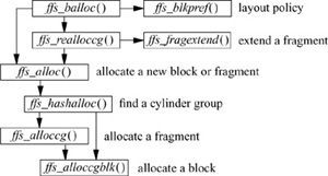
The procedural description of the allocation process is shown in Fig. 8.5. Ffs_balloc() is the routine responsible for determining when a new block must be allocated. It first calls the layout-policy routine ffs_blkpref() to select the most desirable block based on the preference from the global-policy routines that were described earlier in this section. If a fragment has already been allocated and needs to be extended, ffs_balloc() calls ffs_realloccg(). If nothing has been allocated yet, ffs_balloc() calls ffs_alloc().
Ffs_realloccg() first tries to extend the current fragment in place. Consider the sample block of an allocation map with two fragments allocated from it, shown in Fig. 8.6. The first fragment can be extended from a size 2 fragment to a size 3 or a size 4 fragment, since the two adjacent fragments are unused. The second fragment cannot be extended, as it occupies the end of the block, and fragments are not allowed to span blocks. If ffs_realloccg() is able to expand the current fragment in place, the map is updated appropriately and it returns. If the fragment cannot be extended, ffs_realloccg() calls the ffs_alloc() routine to get a new fragment. The old fragment is copied to the beginning of the new fragment, and the old fragment is freed.
Figure 8.6 Sample block with two allocated fragments.
![]()
The bookkeeping tasks of allocation are handled by ffs_alloc(). It first verifies that a block is available in the desired cylinder group by checking the filesystem summary information. If the summary information shows that the cylinder group is full, ffs_alloc() quadratically rehashes through the summary information looking for a cylinder group with free space. Having found a cylinder group with space, ffs_alloc() calls either the fragment-allocation routine or the block-allocation routine to acquire a fragment or block.
The block-allocation routine is given a preferred block. If that block is available, it is returned. If the block is unavailable, the allocation routine tries to find another block on the same cylinder that is rotationally close to the requested block. So that the task of locating rotationally optimal blocks is simplified, the summary information for each cylinder group includes a count of the available blocks at different rotational positions. By default, eight rotational positions are distinguished; that is, the resolution of the summary information is 2 milliseconds for a 3600 revolution-per-minute drive. The superblock contains an array of lists called the rotational-layout table. The array is indexed by rotational position. Each entry in the array lists the index into the block map for every data block contained in its rotational position. When searching for a block to allocate, the system first looks through the summary information for a rotational position with a nonzero block count. It then uses the index of the rotational position to find the appropriate list of rotationally optimal blocks. This list enables the system to limit its scan of the free-block map to only those parts that contain free, rotationally well-placed blocks.
The fragment-allocation routine is given a preferred fragment. If that fragment is available, it is returned. If the requested fragment is not available, and the filesystem is configured to optimize for space utilization, the filesystem uses a best-fit strategy for fragment allocation. The fragment-allocation routine checks the cylinder-group summary information, starting with the entry for the desired size, and scanning larger sizes until an available fragment is found. If there are no fragments of the appropriate size or larger, then a full-sized block is allocated and is broken up.
If an appropriate-sized fragment is listed in the fragment summary, then the allocation routine expects to find it in the allocation map. To speed up the process of scanning the potentially large allocation map, the filesystem uses a table-driven algorithm. Each byte in the map is treated as an index into a fragment-descriptor table. Each entry in the fragment-descriptor table describes the fragments that are free for that corresponding map entry. Thus, by doing a logical AND with the bit corresponding to the desired fragment size, the allocator can determine quickly whether the desired fragment is contained within a given allocation-map entry. As an example, consider the entry from an allocation map for the 8192/1024 filesystem shown in Fig. 8.7. The map entry shown has already been fragmented, with a single fragment allocated at the beginning and a size 2 fragment allocated in the middle. Remaining unused is another size 2 fragment, and a size 3 fragment. Thus, if we look up entry 115 in the fragment table, we find the entry shown in Fig. 8.8. If we were looking for a size 3 fragment, we would inspect the third bit and find that we had been successful; if we were looking for a size 4 fragment, we would inspect the fourth bit and find that we needed to continue. The C code that implements this algorithm is as follows:
Figure 8.7 Map entry for an 8192/1024 filesystem.
![]()
               for (i = 0; i < MAPSIZE; i++)
                   if (fragtbl[allocmap[i]] & (1 << (size - 1)))
                       break;
Using a best-fit policy has the benefit of minimizing disk fragmentation; however, it has the undesirable property that it maximizes the number of fragment-to-fragment copies that must be made when a process writes a file in many small pieces. To avoid this behavior, the system can configure filesystems to optimize for time, rather than for space. The first time that a process does a small write on a filesystem configured for time optimization, it is allocated a best-fit fragment. On the second small write, however, a full-sized block is allocated, with the unused portion being freed. Later small writes are able to extend the fragment in place, rather than requiring additional copy operations. Under certain circumstances, this policy can cause the disk to become heavily fragmented. The system tracks this condition, and automatically reverts to optimizing for space if the percentage of fragmentation reaches one-half of the minimum free-space limit.
Block Clustering
Most machines running 4.4BSD do not have separate I/O processors. The main CPU must take an interrupt after each disk I/O operation; if there is more disk I/O to be done, it must select the next buffer to be transferred and must start the operation on that buffer. Before the advent of track-caching controllers, the filesystem obtained its highest throughput by leaving a gap after each block to allow time for the next I/O operation to be scheduled. If the blocks were laid out without a gap, the throughput would suffer because the disk would have to rotate nearly an entire revolution to pick up the start of the next block.
Figure 8.8 Fragment-table entry for entry 115.
![]()
Track-caching controllers have a large buffer in the controller that continues to accumulate the data coming in from the disk even after the requested data have been received. If the next request is for the immediately following block, the controller will already have most of the block in its buffer, so it will not have to wait a revolution to pick up the block. Thus, for the purposes of reading, it is possible to nearly double the throughput of the filesystem by laying out the files contiguously, rather than leaving gaps after each block.
Unfortunately, the track cache is less useful for writing. Because the kernel does not provide the next data block until the previous one completes, there is still a delay during which the controller does not have the data to write, and it ends up waiting a revolution to get back to the beginning of the next block. One solution to this problem is to have the controller give its completion interrupt after it has copied the data into its cache, but before it has finished writing them. This early interrupt gives the CPU time to request the next I/O before the previous one completes, thus providing a continuous stream of data to write to the disk.
This approach has one seriously negative side effect. When the I/O completion interrupt is delivered, the kernel expects the data to be on stable store. Filesystem integrity and user applications using the fsync system call depend on these semantics. These semantics will be violated if the power fails after the I/O completion interrupt but before the data are written to disk. Some vendors eliminate this problem by using nonvolatile memory for the controller cache and providing microcode restart after power fail to determine which operations need to be completed. Because this option is expensive, few controllers provide this functionality.
The 4.4BSD system uses I/O clustering to avoid this dilemma. Clustering was first done by Santa Cruz Operations [Peacock, 1988] and Sun Microsystems [McVoy & Kleiman, 1991]; the idea was later adapted to 4.4BSD [Seltzer et al, 1993]. As a file is being written, the allocation routines try to allocate up to 64 Kbyte of data in contiguous disk blocks. Instead of the buffers holding these blocks being written as they are filled, their output is delayed. The cluster is completed when the limit of 64 Kbyte of data is reached, the file is closed, or the cluster cannot grow because the next sequential block on the disk is already in use by another file. If the cluster size is limited by a previous allocation to another file, the filesystem is notified and is given the opportunity to find a larger set of contiguous blocks into which the cluster may be placed. If the reallocation is successful, the cluster continues to grow. When the cluster is complete, the buffers making up the cluster of blocks are aggregated and passed to the disk controller as a single I/O request. The data can then be streamed out to the disk in a single uninterrupted transfer.
A similar scheme is used for reading. If the ffs_read() discovers that a file is being read sequentially, it inspects the number of contiguous blocks returned by ufs_bmap() to look for clusters of contiguously allocated blocks. It then allocates a set of buffers big enough to hold the contiguous set of blocks and passes them to the disk controller as a single I/O request. The I/O can then be done in one operation. Although read clustering is not needed when track-caching controllers are available, it reduces the interrupt load from systems that have them, and it speeds low-cost systems that do not have them.
For clustering to be effective, the filesystem must be able to allocate large clusters of contiguous blocks to files. If the filesystem always tried to begin allocation for a file at the beginning of a large set of contiguous blocks, it would soon use up its contiguous space. Instead, it uses an algorithm similar to that used for the management of fragments. Initially, file blocks are allocated via the standard algorithm described in the previous two subsections. Reallocation is invoked when the standard algorithm does not result in a contiguous allocation. The reallocation code searches a cluster map that summarizes the available clusters of blocks in the cylinder group. It allocates the first free cluster that is large enough to hold the file, then moves the file to this contiguous space. This process continues until the current allocation has grown to a size equal to the maximum permissible contiguous set of blocks (typically 16 blocks). At that point, the I/O is done, and the process of allocating space begins again.
Unlike fragment reallocation, block reallocation to different clusters of blocks does not require extra I/O or memory-to-memory copying. The data to be written are held in delayed write buffers. Within that buffer is the disk location to which the data are to be written. When the location of the block cluster is relocated, it takes little time to walk the list of buffers in the cluster and to change the disk addresses to which they are to be written. When the I/O occurs, the final destination has been selected and will not change.
To speed the operation of finding clusters of blocks, the filesystem maintains a cluster map with 1 bit per block (in addition to the map with 1 bit per fragment). It also has summary information showing how many sets of blocks there are for each possible cluster size. The summary information allows it to avoid looking for cluster sizes that do not exist. The cluster map is used because it is faster to scan than is the much larger fragment bitmap. The size of the map is important because the map must be scanned bit by bit. Unlike fragments, clusters of blocks are not constrained to be aligned within the map. Thus, the table-lookup optimization done for fragments cannot be used for look up of clusters.
The filesystem relies on the allocation of contiguous blocks to achieve high levels of performance. The fragmentation of free space may increase with time or with filesystem utilization. This fragmentation can degrade performance as the filesystem ages. The effects of utilization and aging were measured on over 50 filesystems at Harvard University. The measured filesystems ranged in age since initial creation from 1 to 3 years. The fragmentation of free space on most of the measured filesystems caused performance to degrade no more than 10 percent from that of a newly created empty filesystem. The most severe degradation measured was 30 percent on a highly active filesystem that had many small files and was used to spool USENET news [Seltzer et al, 1995].
Synchronous Operations
If the system crashes or stops suddenly because of a power failure, the filesystem may be in an inconsistent state. To ensure that the on-disk state of the filesystem can always be returned deterministically to a consistent state, the system must do three operations synchronously:
1. Write a newly allocated inode to disk before its name is entered into a directory.
2. Remove a directory name before the inode is deallocated.
3. Write a deallocated inode to disk before its blocks are placed into the cylinder-group free list.
These synchronous operations ensure that directory names always reference valid inodes, and that no block is ever claimed by more than one inode. Because the filesystem must do two synchronous operations for each file that it creates, and for each file that it deletes, the filesystem throughput is limited to the disk-write speed when many files are created or deleted simultaneously.
Three techniques have been used to eliminate these synchronous operations:
1. Put stable store (battery–backed-up memory) on the disk-controller board. Filesystem operations can then proceed as soon as the block to be written is copied into the stable store. If the system fails, unfinished disk operations can be completed from the stable store when the system is rebooted [Moran et al, 1990].
2. Keep a log of filesystem updates on a separate disk or in stable store. Filesystem operations can then proceed as soon as the operation to be done is written into the log. If the system fails, unfinished filesystem operations can be completed from the log when the system is rebooted [Chutani et al, 1992].
3. Maintain a partial ordering on filesystem update operations. Before committing a change to disk, ensure that all operations on which it depends have been completed. For example, an operation that would write an inode with a newly allocated block to disk would ensure that a deallocated inode that previously owned the block had been written to disk first. Using a technique of partial rollback to break circular dependencies, this algorithm can eliminate 95 percent of the synchronous writes [Ganger & Patt, 1994].
The first technique ensures that the filesystem is always consistent after a crash and can be used as soon as the system reboots. The second technique ensures that the filesystem is consistent as soon as a log rollback has been done. The third technique still requires that the filesystem-check program be run to restore the consistency of the filesystem; however, it does not require any specialized hardware or additional disk space to do logging. All these techniques have been developed in derivatives of the FFS, although none of them are currently part of the 4.4BSD distribution.
8.3 The Log-Structured Filesystem
The factors that limited the performance of the implementation of the FFS found in historic versions of 4BSD are the FFS’s requirement for synchronous I/O during file creation and deletion, and the seek times between I/O requests for different files. The synchronous I/O used during file creation and deletion is necessary for filesystem recoverability after failures. The worst-case example is that it normally takes five separate disk I/O’s (two synchronous, three asynchronous), each preceded by a seek, to create a new file in the FFS: The file inode is written twice, the containing directory is written once, the containing directory’s inode is written once, and, of course, the file’s data are written. This synchronous behavior is rarely an issue. Unimaginative benchmarks to the contrary, few applications create large numbers of files, and fewer still immediately delete those files.
Seek times between I/O requests to a single file are significant only when the file has been allocated poorly on disk. The FFS does an excellent job of laying out files on disk, and, as long as the disk remains empty enough to permit good allocation, it can read and write individual files at roughly 50 percent of the disk bandwidth, skipping one disk block for every one read or written. In 4.4BSD, where clustering has been added, or when using a disk controller that supports track caching, the FFS can transfer at close to the full bandwidth of the disk. For these reasons, the seek times between I/O requests for different files will often dominate performance. (As an example, on a typical disk, an average seek takes only slightly less time than a disk rotation, so many blocks can be written in the time that it takes to seek to a new location on the disk.)
As the main-memory buffer cache has become larger over the past decade, applications have tended to experience this problem only when writing to the disk. Repeated reads of data will go to the disk only the first time, after which the data are cached and no further I/O is required. In addition, doing read-ahead further amends this problem, as sequential reads of a file will wait for only the first data block to transfer from disk. Later reads will find the data block already in the cache, although a separate I/O will still have been done. In summary, the problem to be solved in modern filesystem design is that of writing a large volume of data, from multiple files, to the disk. If the solution to this problem eliminates any synchronous I/O, so much the better.
The LFS, as proposed by Ousterhout and Douglis [Ousterhout & Douglis, 1989], attempted to address both the problem and the issue of synchronous I/O. The fundamental idea of the LFS is to improve filesystem performance by storing all filesystem data in a single, contiguous log. The LFS is optimized for writing, and no seek is required between writes, regardless of the file to which the writes belong. It is also optimized for reading files written in their entirety over a brief period (as is the norm in workstation environments) because the files are placed contiguously on disk.
The FFS provides logical locality, as it attempts to place related files (e.g., files from the same directory) in the same cylinder group. The LFS provides temporal locality, as it places files created at about the same time together on disk, relying on the buffer cache to protect the application from any adverse effects of this decision. It is important to realize that no performance characteristics of the disk or processor are taken into account by the LFS. The assumption that the LFS makes is that reads are cached, and that writes are always contiguous. Therefore, a simpler model of disk activity suffices.
Organization of the Log-Structured Filesystem
The LFS is described by a superblock similar to the one used by the FFS. In addition, to minimize the additional software needed for the LFS, FFS index structures (inodes) and directories are used almost without change, making tools written to analyze the FFS immediately applicable to the LFS (a useful result in itself). Where the LFS differs from the FFS is in the layout of the inode, directory and file data blocks on disk.
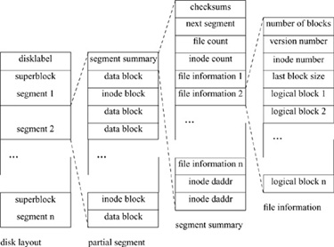
The underlying structure of the LFS is that of a sequential, append-only log. The disk is statically partitioned into fixed-sized contiguous segments, (which are generally 0.5 to 1 Mbyte), as shown by the disk-layout column of Fig. 8.9. The initial superblock is in the same location as in the FFS, and is replicated throughout the disk in selected segments. All writes to the disk are appended to the logical end of the log. Although the log logically grows forever, portions of the log that have already been written must be made available periodically for reuse because the disk is not infinite in length. This process is called cleaning, and the utility that performs this reclamation is called the cleaner. The need for cleaning is the reason that the disk is logically divided into segments. Because the disk is divided into reasonably large static areas, it is easy to segregate the portions of the disk that are currently being written from those that are currently being cleaned. The logical order of the log is not fixed, and the log should be viewed as a linked list of segments, with segments being periodically cleaned, detached from their current position in the log, and reattached after the end of the log.
Figure 8.9 Log-Structured Filesystem layout.
In ideal operation, the LFS accumulates dirty blocks in memory. When enough blocks have been accumulated to fill a segment, they are written to the disk in a single, contiguous I/O operation. Since it makes little sense to write data blocks contiguously and continue to require seeks and synchronous writes to update their inode-modification times, the modified inodes are written into the segment at the same time as the data. As a result of this design goal, inodes are no longer in fixed locations on the disk, and the LFS requires an additional data structure called the inode map, which maps inode numbers to the current disk addresses of the blocks containing them. So that fast recovery after crashes is facilitated, the inode map is also stored on disk (the inode map would be time consuming to recreate after system failure).
As the LFS writes dirty data blocks to the logical end of the log (that is, into the next available segment), modified blocks will be written to the disk in locations different from those of the original blocks. This behavior is called a no-overwrite policy, and it is the responsibility of the cleaner to reclaim space resulting from deleted or rewritten blocks. Generally, the cleaner reclaims space in the filesystem by reading a segment, discarding dead blocks (blocks that belong to deleted files or that have been superseded by rewritten blocks), and rewriting any live blocks to the end of the log.
In a workstation environment, the LFS usually will not accumulate many dirty data blocks before having to write at least some portion of the accumulated data. Reasons that writes must happen include the requirement of the Network Filesystem (NFS) that write operations be flushed to the disk before the write call returns, and that UNIX filesystems (and POSIX standards) have historically guaranteed that closing a file descriptor both updates the inode and flushes pending write operations to the disk.
Because the LFS can only rarely write full segments, each segment is further partitioned into one or more partial segments. A partial segment can be thought of as the result of a single write operation to disk. Each partial segment is composed of a single partial-segment summary, and inode blocks and data blocks, as shown by the partial-segment column of Fig. 8.9. The segment summary describes the inode and data blocks in the partial segment, and is shown by the segment-summary column of Fig. 8.9. The partial-segment summary contains the following information:
• Checksums for the summary information and for the entire partial segment
• The time that the partial segment was written (not shown in Fig. 8.9)
• Directory-operation information (not shown in Fig. 8.9)
• The disk address of the segment to be written immediately after this segment
• The number of file-information structures and the number of inode disk addresses that follow
• A file-information structure for each separate file for which blocks are included in this partial segment (described next)
• A disk address for each block of inodes included in this partial segment
The checksums are necessary for the recovery agent to determine that the partial segment is complete. Because disk controllers do not guarantee that data are written to disk in the order that write operations are issued, it is necessary to be able to determine that the entire partial segment has been written to the disk successfully. Writing a single disk sector’s worth of the partial-segment summary after the rest of the partial segment was known to have been written successfully would largely avoid this problem; however, it would have a catastrophic effect on filesystem performance, as there would be a significant rotational latency between the two writes. Instead, a checksum of 4 bytes in each block of the partial segment is created and provides validation of the partial segment, permitting the filesystem to write multiple partial segments without an intervening seek or rotation.
The file-information structures and inode disk addresses describe the rest of the partial segment. The number of file-information structures and blocks of inodes in the partial segment is specified in the segment-summary portion of the partial segment. The inode blocks are identical to the FFS inode blocks. The disk address of each inode block is also specified in the partial-segment summary information, and can be retrieved easily from that structure. Blocks in the partial segment that are not blocks of inodes are file data blocks, in the order listed in the partial-segment summary information.
The file-information structures are as shown by the file-information column of Fig. 8.9. They contain the following information:
• The number of data blocks for this file contained in this partial segment
• Aversion number for the file, intended for use by the cleaner
• The file’s inode number
• The size of the block written most recently to the file in this partial segment
• The logical block number for the data blocks in this partial segment
Index File
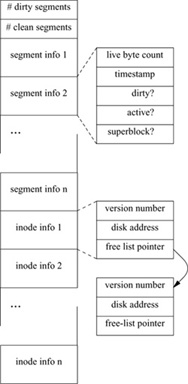
The final data structure in the LFS is known as the index file (shown in Fig. 8.10), because it contains a mapping from the inode number to the disk address of the block that contains the inode. The index file is maintained as a regular, read-only file visible in the filesystem, named ifile by convention.
Figure 8.10 Log-Structured Filesystem index-file structure.
There are two reasons for the index file to be implemented as a regular file. First, because the LFS does not allocate a fixed position for each inode when created, there is no reason to limit the number of inodes in the filesystem, as is done in the FFS. This feature permits the LFS to support a larger range of uses because the filesystem can change from being used to store a few, large files (e.g., an X11 binary area) to storing many files (e.g., a home directory or news partition) without the filesystem being recreated. In addition, there is no hard limit to the number of files that can be stored in the filesystem. However, this lack of constraints requires that the inode map be able to grow and shrink based on the filesystem’s inode usage. Using an already established mechanism (the kernel file code) minimizes the special-case code in the kernel.
Second, the information found in the index file is used by the cleaner. The LFS cleaner is implemented as a user-space process, so it is necessary to make the index-file information accessible to application processes. Again, because the index file is visible in the filesystem, no additional mechanism is required, minimizing the special-case code in both the kernel and the cleaner.
Because the index file’s inode and data blocks are themselves written to new locations each time that they are written, there must be a fixed location on the disk that can be used to find them. This location is the superblock. The first superblock is always in the same position on the disk and contains enough information for the kernel to find the disk address of the block of inodes that contains the index file’s inode.
In addition to the inode map, the index file includes the other information that is shared between the kernel and the cleaner. The index file contains information:
• It contains the number of clean and dirty segments.
• It records segment-usage information, one entry per segment (rather than per partial segment) on the disk. The segment-usage information includes the number of live bytes currently found in the segment; the most recent modification time of the segment; and flags that show whether the segment is currently being written, whether the segment was written since the most recent checkpoint (checkpoints are described in the writing to the log subsection), whether the segment has been cleaned, and whether the segment contains a copy of the superblock. Because segment-based statistics are maintained on the amount of useful information that is currently in the segment, it is possible to clean segments that contain a high percentage of useless data, so that the maximum amount of space is made available for reuse with the minimal amount of cleaning.
• It maintains inode information, one entry per current inode in the filesystem. The inode information includes the current version number of the inode, the disk address of the block of inodes that contains the inode, and a pointer if the inode is unused and is on the current list of free inodes.
So that calculations are simplified, segment-summary-information entries and inode-map entries are block aligned and are not permitted to span block boundaries, resulting in a fixed number of each type of entry per block. This alignment makes it possible for the filesystem to calculate easily the logical block of the index file that contains the correct entry.
Reading of the Log
To clarify the relationships among these structures, we shall consider the steps necessary to read a single block of a file if the file’s inode number is known and there is no other information available.
1. Read in the superblock. The superblock contains the index file’s inode number, and the disk address of the block of inodes that contains the index file’s inode.
2. Read in the block of inodes that contains the index file’s inode. Search the block and find the index file’s inode. Inode blocks are searched linearly. No more complicated search or data structure is used, because, on the average, in an 8-Kbyte–block filesystem, only 32 or so memory locations need to be checked for any given inode in a block to be located.
3. Use the disk addresses in the index file’s inode and read in the block of the index file that contains the inode-map entry for the requested file’s inode.
4. Take the disk address found in the inode-map entry and use it to read in the block of inodes that contains the inode for the requested file. Search the block to find the file’s inode.
5. Use the disk addresses found in the file’s inode to read in the blocks of the requested file.
Normally, all this information would be cached in memory, and the only real I/O would be a single I/O operation to bring the file’s data block into memory. However, it is important to minimize the information stored in the index file to ensure that the latter does not reserve unacceptable amounts of memory.
Writing to the Log
When a dirty block must be flushed to the disk for whatever reason (e.g., because of a fsync or sync system call, or because of closing a file descriptor), the LFS gathers all the dirty blocks for the filesystem and writes them sequentially to the disk in one or more partial segments. In addition, if the number of currently dirty buffers approaches roughly one-quarter of the total number of buffers in the system, the LFS will initiate a segment write regardless.
The filesystem does the write by traversing the vnode lists linked to the filesystem mount point and collecting the dirty blocks. The dirty blocks are sorted by file and logical block number (so that files and blocks within files will be written as contiguously as possible), and then are assigned disk addresses. Their associated meta-data blocks (inodes and indirect blocks) are updated to reflect the new disk addresses, and the meta-data blocks are added to the information to be written. This information is formatted into one or more partial segments, partial segment summaries are created, checksums are calculated, and the partial segments are written into the next available segment. This process continues until all dirty blocks in the filesystem have been written.
Periodically, the LFS synchronizes the information on disk, such that all disk data structures are completely consistent. This state is known as a filesystem checkpoint. Normally, a checkpoint occurs whenever the sync system call is made by the update utility, although there is no reason that it cannot happen more or less often. The only effect of changing how often the filesystem checkpoints is that the time needed to recover the filesystem after system failure is inversely proportional to the frequency of the checkpoints. The only requirement is that the filesystem be checkpointed between the time that a segment is last written and the time that the segment is cleaned, to avoid a window where system failure during cleaning of a segment could cause the loss of data that the kernel has already confirmed as being written safely to disk.
For the filesystem to be checkpointed, additional data structures must be written to disk. First, because each file inode is written into a new location each time that it is written, the index file must also be updated and its dirty meta-data blocks written. The flags in the segment usage information that note if each segment was written since the most recent checkpoint must be toggled and written as part of this update. Second, because the index-file inode will have been modified, it too must be written, and the superblock must be updated to reflect its new location. Finally, the superblock must be written to the disk. When these objects have been updated and written successfully, the filesystem is considered checkpointed.
The amount of information needing to be written during a filesystem checkpoint is proportional to the amount of effort the recovery agent is willing to make after system failure. For example, it would be possible for the recovery agent to detect that a file was missing an indirect block, if a data block existed for which there was no appropriate indirect block, in which case, indirect blocks for files would not have to be written during normal writes or checkpoints. Or, the recovery agent could find the current block of inodes that contains the latest copy of the index file inode by searching the segments on the disk for a known inode number, in which case the superblock would not need to be updated during checkpoint. More aggressively, it would be possible to rebuild the index file after system failure by reading the entire disk, so the index file would not have to be written to complete a checkpoint. Like the decision of how often to checkpoint, the determination of the tradeoff between what is done by the system during filesystem checkpoint and what is done by the recovery agent during system recovery is a flexible decision.
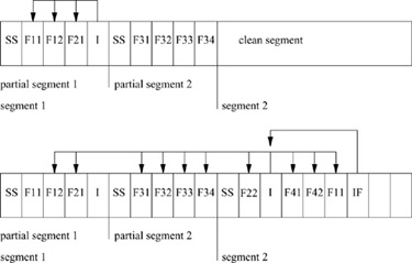
Writes to a small fragment of a LFS are shown in Fig. 8.11. Note that the no-overwrite policy of the LFS results in the latter using far more disk space than is used by the FFS, a classic space–time tradeoff: Although more space is used, because the disk I/O is contiguous on disk, it requires no intermediate seeks.
Block Accounting
Block accounting in the LFS is far more complex than in the FFS. In the FFS, blocks are allocated as needed, and, if no blocks are available, the allocation fails. The LFS requires two different types of block accounting.
The first form of block accounting is similar to that done by the FFS. The LFS maintains a count of the number of disk blocks that do not currently contain useful data. The count is decremented whenever a newly dirtied block enters the buffer cache. Many files die in the cache, so this number must be incremented whenever blocks are deleted, even if the blocks were never written to disk. This count provides a system-administration view of how much of the filesystem is currently in use. However, this count cannot be used to authorize the acceptance of a write from an application because the calculation implies that blocks can be written successfully into the cache that will later fail to be written to disk. For example, this failure could be caused by the disk filling up because the additional blocks necessary to write dirty blocks (e.g., meta-data blocks and partial-segment summary blocks) were not considered in this count. Even if the disk were not full, all the available blocks might reside in uncleaned segments, and new data could not be written.
Figure 8.11 Log-Structured Filesystem fragment. In the first snapshot, the first partial segment contains a segment summary (SS), two blocks from file 1 (F11 and F12), a single block from file 2 (F21), and a block of inodes (I). The block of inodes contains the inodes (and therefore the disk addresses) for files F1 and F2. The second partial segment contains a segment summary and four blocks from file 3. In the second snapshot, a block has been appended to file 2 (F22); a new file, file 4, has been written that has two blocks (F41 and F42); and the first block of file 1 (F11) has been modified and therefore rewritten. Because the disk addresses for files 1 and 2 have changed, and the inodes for files 3 and 4 have not yet been written, those files‘ inodes are written (I). Note that this inode block still references disk addresses in the first and second partial segments, because blocks F12 and F21, and the blocks from file 3, are still live. Since the locations of the files‘ inodes have changed, if the filesystem is to be consistent on disk, the modified blocks from the index file (IF) must be written as well.
The second form of block accounting is a count of the number of disk blocks currently available for writing—that is, that reside in segments that are clean and ready to be written. This count is decremented whenever a newly dirtied block enters the cache, and the count is not incremented until the block is discarded or the segment into which it is written is cleaned. This accounting value is the value that controls cleaning initiation. If an application attempts to write data, but there is no space currently available for writing, the application will block until space is available. Using this pessimistic accounting to authorize writing guarantees that, if the operating system accepts a write request from the user, it will be able to do that write, barring system failure.
The accounting support in the LFS is complex. This complexity arises because allocation of a block must also consider the allocation of any necessary meta-data blocks and any necessary inode and partial-segment summary blocks. Determining the actual disk space required for any block write is difficult because inodes are not collected into inode blocks, and indirect blocks and segment summaries are not created until the partial segments are actually written. Every time an inode is modified in the inode cache, a count of inodes to be written is incremented. When blocks are dirtied, the number of available disk blocks is decremented. To decide whether there is enough disk space to allow another write into the cache, the system computes the number of segment summaries necessary to write the dirty blocks already in the cache, adds the number of inode blocks necessary to write the dirty inodes, and compares that number to the amount of space currently available to be written. If insufficient space is available, either the cleaner must run or dirty blocks in the cache must be deleted.
The Buffer Cache
Before the integration of the LFS into 4BSD, the buffer cache was thought to be filesystem-independent code. However, the buffer cache contained assumptions about how and when blocks are written to disk. The most significant problem was that the buffer cache assumed that any single dirty block could be flushed to disk at any time to reclaim the memory allocated to the block. There are two problems with this assumption:
1. Flushing blocks a single block at a time would destroy any possible performance advantage of the LFS, and, because of the modified meta-data and partial-segment summary blocks, the LFS would use enormous amounts of disk space.
2. Also because of the modified meta-data and partial-segment summary blocks, the LFS requires additional memory to write: If the system were completely out of memory, it would be impossible for the LFS to write anything at all.
For these reasons, the LFS needs to guarantee that it can obtain the additional buffers that it needs when it writes a segment, and that it can prevent the buffer cache from attempting to flush blocks backed by a LFS. To handle these problems, the LFS maintains its dirty buffers on the kernel LOCKED queue, instead of on the traditional LRU queue, so that the buffer cache does not attempt to reclaim them. Unfortunately, maintaining these buffers on the LOCKED queue exempts most of the dirty LFS blocks from traditional buffer-cache behavior, which undoubtedly alters system performance in unexpected ways. To prevent the LFS from locking down all the available buffers and to guarantee that there are always additional buffers available when they are needed for segment writing, the LFS begins segment writing as described previously, when the number of locked-down buffers exceeds a threshold. In addition, the kernel blocks any process attempting to acquire a block from a LFS if the number of currently locked blocks is above a related access threshold. Buffer allocation and management will be much more reasonably handled by systems with better integration of the buffer cache and virtual memory.
Another problem with the historic buffer cache was that it was a logical buffer cache, hashed by vnode and file logical block number. In the FFS, since indirect blocks did not have logical block numbers, they were hashed by the vnode of the raw device (the file that represents the disk partition) and the disk address. Since the LFS does not assign disk addresses until the blocks are written to disk, indirect blocks have no disk addresses on which to hash. So that this problem could be solved, the block name space had to incorporate meta-data block numbering. Block numbers were changed to be signed integers, with negative block numbers referencing indirect blocks and zero and positive numbers referencing data blocks. Singly indirect blocks take on the negative block number of the first data block to which they point. Doubly and triply indirect blocks take the next-lower negative number of the singly or doubly indirect block to which they point. This approach makes it possible for the filesystem to traverse the indirect block chains in either direction, facilitating reading a block or creating indirect blocks. Because it was possible for the FFS also to use this scheme, the current hash chains for both filesystems are done in this fashion.
Directory Operations
Directory operations include those system calls that affect more than one inode (typically a directory and a file). They include create, link, mkdir, mknod, remove, rename, rmdir, and symlink. These operations pose a special problem for the LFS. Since the basic premise of the LFS is that small I/O operations can be postponed and then coalesced to provide larger I/O operations, retaining the synchronous behavior of directory operations would make little sense. In addition, the UNIX semantics of directory operations are defined to preserve ordering (e.g., if the creation of one file precedes the creation of another, any recovery state of the filesystem that includes the second file must also include the first). This semantic is used in UNIX filesystems to provide mutual exclusion and other locking protocols. Since directory operations affect multiple inodes, we must guarantee that either all inodes and associated changes are written successfully to the disk, or that any partially written information is ignored during recovery.
The basic unit of atomicity in LFS is the partial segment because the checksum information guarantees that either all or none of the partial segment will be considered valid. Although it would be possible to guarantee that the inodes for any single directory operation would fit into a partial segment, that would require each directory operation to be flushed to the disk before any vnode participating in it is allowed to participate in another directory operation, or a potentially extremely complex graph of vnode interdependencies has to be maintained. Instead, a mechanism was introduced to permit directory operations to span multiple partial segments. First, all vnodes participating in any directory operation are flagged. When the partial segment containing the first of the flagged vnodes is written, the segment summary flag SS_DIROP is set. If the directory-operation information spans multiple partial segments, the segment summary flag SS_CONT also is set. So that the number of partial segments participating in a set of directory operations is minimized, vnodes are included in partial segments based on whether they participated in a directory operation. Finally, so that directory operations are prevented from being only partially reflected in a segment, no new directory operations are begun while the segment writer is writing a partial segment containing directory operations, and the segment writer will not write a partial segment containing directory operations while any directory operation is in progress.
During recovery, partial segments with the SS_DIROP or SS_CONT flag set are ignored unless the partial segment completing the directory operation was written successfully to the disk. For example, if the recovery agent finds a segment with both SS_DIROP and SS_CONT set, it ignores all such partial segments until it finds a later partial segment with SS_DIROP set and SS_CONT unset (i.e. the final partial segment including any part of this set of directory operations). If no such partial segment is ever found, then all the segments from the initial directory operation on are discarded.
Creation of a File
Creating a file in the LFS is a simple process. First, a new inode must be allocated from the filesystem. There is a field in the superblock that points to the first free inode in the linked list of free inodes found in the index file. If this pointer references an inode, that inode is allocated in the index file, and the pointer is updated from that inode’s free-list pointer. Otherwise, the index file is extended by a block, and the block is divided into index-file inode entries. The first of these entries is then allocated as the new inode.
The inode version number is then incremented by some value. The reason for this increment is that it makes the cleaner’s task simpler. Recall that there is an inode version number stored with each file-information structure in the segment. When the cleaner reviews a segment for live data, mismatching version numbers or an unallocated index file inode makes detection of file removal simple.
Conversely, deleting a file from the LFS adds a new entry to the index file’s free-inode list. Contrasted to the multiple synchronous operations required by the FFS when a file is created, creating a file in LFS is conceptually simple and blindingly fast. However, the LFS pays a price for avoiding the synchronous behavior: It cannot permit segments to be written at the same time as files are being created, and the maintenance of the allocation information is significantly more complex.
Reading and Writing to a File
Having created a file, a process can do reads or writes on it. The procedural path through the kernel is largely identical to that of the FFS, as shown by Fig. 8.4 with the ffs_ routines changed to lfs_. The code for ffs_read() and lfs_read(), and that for ffs_write() and lfs_write(), is the same, with some C preprocessing #defines added for minor tailoring. As in the FFS, each time that a process does a write system call, the system checks to see whether the size of the file has increased. If the file needs to be extended, the request is rounded up to the next fragment size, and only that much space is allocated. A logical block request is handed off to lfs_balloc(), which performs the same functions as ffs_balloc(), allocating any necessary indirect blocks and the data block if it has not yet been allocated, and reallocating and rewriting fragments as necessary.
Filesystem Cleaning
Because the disk is not infinite, cleaning must be done periodically to make new segments available for writing. Cleaning is the most challenging aspect of the LFS, in that its effect on performance and its interactions with other parts of the system are still not fully understood.
Although a cleaner was simulated extensively in the original LFS design [Rosenblum & Ousterhout, 1992], the simulated cleaner was never implemented, and none of the implemented cleaners (including the one in 4BSD) have ever been simulated. Cleaning must be done often enough that the filesystem does not fill up; however, the cleaner can have a devastating effect on performance. Recent research [Seltzer et al, 1995] shows that cleaning segments while the LFS is active (i.e., writing other segments) can result in a performance degradation of about 35 to 40 percent for some transaction-processing–oriented applications. This degradation is largely unaffected by how full the filesystem is; it occurs even when the filesystem is half empty. However, even at 40-percent degradation, the LFS performs comparably to the FFS on these applications. Recent research also shows that typical workstation workloads can permit cleaning during disk idle periods [Blackwell et al, 1995], without introducing any user-noticeable latency.
Cleaning in the LFS is implemented by a user utility named lfs_cleanerd. This functionality was placed in user space for three major reasons.
First, experimentation with different algorithms, such as migrating rarely accessed data to the same segment or restricting cleaning to disk idle times, probably will prove fruitful, and making this experimentation possible outside the operating system will encourage further research. In addition, a single cleaning algorithm is unlikely to perform equally well for all possible workloads. For example, coalescing randomly updated files during cleaning should dramatically improve later sequential-read performance for some workloads.
Second, the cleaner may potentially require large amounts of memory and processor time, and previous implementations of the cleaner in the kernel have caused noticeable latency problems in user response. When the cleaner is moved to user space, it competes with other processes for processor time and virtual memory, instead of tying down a significant amount of physical memory.
Third, given the negative effect that the cleaner can have on performance, and the many possible algorithms for deciding when and what segments to clean, running the cleaner is largely a policy decision, always best implemented outside the kernel.
The number of live bytes of information in a segment, as determined from the segment-usage information in the index file, is used as a measure of cleaning importance. A simple algorithm for cleaning would be always to clean the segment that contains the fewest live bytes, based on the argument that this rule would result in the most free disk space for the least effort. The cleaning algorithm in the current LFS implementation is based on the simulation in Rosenblum and Ousterhout, 1992. This simulation shows that selection of segments to clean is an important design parameter in minimizing cleaning overhead, and that the cost–benefit policy defined there does well for the simulated workloads. Briefly restated, each segment is assigned a cleaning cost and benefit. The I/O cost to clean a segment is equal to
1 + utilization,
where 1 represents the cost to read the segment to be cleaned, and utilization is the fraction of live data in the segment that must be written back into the log. The benefit of cleaning a segment is
free bytes generated × age of segment,
where free bytes generated is the fraction of dead blocks in the segment (1 – utilization) and age of segment is the number of seconds since the segment was written to disk. The selection of the age of segment metric can have dramatic effects on the frequency with which the cleaner runs (and interferes with system performance).
When the filesystem needs to reclaim space, the cleaner selects the segment with the largest benefit-to-cost ratio:
![]()
Once a segment has been selected for cleaning, by whatever mechanism, cleaning proceeds as follows:
1. Read one (or more) target segments.
2. Determine the blocks that contain useful data. For the cleaner to determine the blocks in a segment that are live, it must be able to identify each block in a segment; so, the summary block of each partial segment identifies the inode and logical block number of every block in the partial segment.
3. Write the live blocks back into the filesystem.
4. Mark the segments as clean.
The cleaner shares information with the kernel via four new system calls and the index file. The new system calls interface to functionality that was used by the kernel (e.g., the translation of file logical block numbers to disk addresses done by ufs_bmap()) and to functionality that must be in the kernel to avoid races between the cleaner and other processes.
The four system calls added for the cleaner are as follows:
1. lfs_bmapv: Take an array of inode number and logical block number pairs, and return the current disk address, if any, for each block. If the disk address returned to the cleaner is the one in the segment that it is considering, the block is live.
2. lfs_markv: Take an array of inode number and logical block number pairs and write their associated data blocks into the filesystem in the current partial segment. Although it would be theoretically possible for the cleaner to accomplish this task itself, the obvious race with other processes writing or deleting the same blocks, and the need to do the write without updating the inode’s access or modification times, made it simpler for this functionality to be in the kernel.
3. lfs_segclean: Mark a segment clean. After the cleaner has rewritten all the live data in the segment, this system call marks the segment clean for reuse. It is a system call so that the kernel does not have to search the index file for new segments and so that the cleaner does not have to modify the index file.
4. lfs_segwait: Make a special-purpose sleep call. The calling process is put to sleep until a specified timeout period has elapsed or, optionally, until a segment has been written. This operation lets the cleaner pause until there may be a requirement for further cleaning.
When a segment is selected and read into memory, the cleaner processes each partial segment in the segment sequentially. The segment summary specifies the blocks that are in the partial segment. Periodically, the cleaner constructs an array of pairs consisting of an inode number and a logical block number, for file blocks found in the segment, and uses the lfs_bmapv system call to obtain the current disk address for each block. If the returned disk address is the same as the location of the block in the segment being examined, the block is live. The cleaner uses the lfs_markv system call to rewrite each live block into another segment in the filesystem.
Before rewriting these blocks, the kernel must verify that none of the blocks have been superseded or deleted since the cleaner called lfs_bmapv. Once the call to lfs_markv begins, only blocks specified by the cleaner are written into the log, until the lfs_markv call completes, so that, if cleaned blocks die after the lfs_markv call verifies that they are alive, the partial segments written after the lfs_markv partial segments will update their status properly.
The separation of the lfs_bmapv and lfs_markv functionality was done deliberately to make it easier for LFS to support new cleaning algorithms. There is no requirement that the cleaner always call lfs_markv after each call to lfs_bmapv, or that it call lfs_markv with the same arguments. For example, the cleaner might use lfs_markv to do block coalescing from several segments.
When the cleaner has written the live blocks using lfs_markv, the cleaner calls lfs_segclean to mark the segment clean. When the cleaner has cleaned enough segments, it calls lfs_segwait, sleeping until the specified timeout elapses or a new segment is written into the filesystem.
Since the cleaner is responsible for producing free space, the blocks that it writes must get preference over all other dirty blocks to be written, so that the system avoids running out of free space. In addition, there are degenerative cases where cleaning a segment can consume more space than it reclaims. So that the cleaner can always run and will eventually generate free space, all writing by any process other than the cleaner is blocked by the kernel when the number of clean segments drops below 3.
Filesystem Parameterization
Parameterization in the LFS is minimal. At filesystem-creation time, it is possible to specify the filesystem block and fragment size, the segment size, and the percentage of space reserved from normal users. Only the last of these parameters may be altered after filesystem creation without recreation of the filesystem.
Filesystem-Crash Recovery
Historic UNIX systems spend a significant amount of time in filesystem checks while rebooting. As disks become ever larger, this time will continue to increase. There are two aspects to filesystem recovery: bringing the filesystem to a physically consistent state and verifying the logical structure of the filesystem. When the FFS or the LFS adds a block to a file, there are several different pieces of information that may be modified: the block itself, its inode, indirect blocks, and, of course, the location of the most recent allocation. If the system crashes between any of the operations, the filesystem is likely to be left in a physically inconsistent state.
There is currently no way for the FFS to determine where on the disk or in the filesystem hierarchy an inconsistency is likely to occur. As a result, it must rebuild the entire filesystem state, including cylinder-group bitmaps and all meta-data after each system failure. At the same time, the FFS verifies the filesystem hierarchy. Traditionally, fsck is the utility that performs both of these functions. Although the addition of filesystem-already-clean flags and tuning fsck has provided a significant decrease in the time that it takes to reboot in 4BSD, it can still take minutes per filesystem before applications can be run.
Because writes are localized in the LFS, the recovery agent can determine where any filesystem inconsistencies caused by the system crash are located, and needs to check only those segments, so bringing a LFS to a consistent state normally requires only a few seconds per filesystem. The minimal time required to achieve filesystem consistency is a major advantage for the LFS over the FFS. However, although fast recovery from system failure is desirable, reliable recovery from media failure is necessary. The high level of robustness that fsck provides for the FFS is not maintained by this consistency checking. For example, fsck is capable of recovering from the corruption of data on the disk by hardware, or by errant software overwriting filesystem data structures such as a block of inodes.
Recovery in the LFS has been separated into two parts. The first part involves bringing the filesystem into a consistent state after a system crash. This part of recovery is more similar to standard database recovery than to fsck. It consists of three steps:
1. Locate the most recent checkpoint—the last time at which the filesystem was consistent on disk.
2. Initialize all the filesystem structures based on that checkpoint.
3. Roll forward, reading each partial segment from the checkpoint to the end of the log, in write order, and incorporating any modifications that occurred, except as noted previously for directory operations.
Support for rolling forward is the purpose of much of the information included in the partial-segment summary. The next-segment pointers are provided so that the recovery agent does not have to search the disk to find the next segment to read. The recovery agent uses the partial-segment checksums to identify valid partial segments (ones that were written completely to the disk). It uses the partial segment time-stamps to distinguish partial segments written after the checkpoint from those that were written before the checkpoint and that were later reclaimed by the cleaner. It uses the file and block numbers in the file-information structures to update the index file (the inode map and segment-usage information) and the file inodes, to make the blocks in the partial segment appear in the file. The latter actions are similar to those taken in cleaning. As happens in database recovery, the filesystem-recovery time is proportional to the interval between filesystem checkpoints.
The second part of recovery in the LFS involves the filesystem-consistency checks performed for the FFS by fsck. This check is similar to the functionality of fsck, and, like fsck, will take a long time to run. (This functionality has not been implemented in 4.4BSD.)
The LFS implementation permits fast recovery, and applications are able to start running as soon as the roll forward has been completed, while basic sanity checking of the filesystem is done in the background. There is the obvious problem of what to do if the sanity check fails. If that happens, the filesystem must be downgraded forcibly to read-only status, and fixed. Then, writes can be enabled once again. The only applications affected by this downgrade are those that were writing to the filesystem. Of course, the root filesystem must always be checked completely after every reboot, to avoid a cycle of reboot followed by crash followed by reboot if the root has become corrupted,
Like the FFS, the LFS replicates the superblock, copying the latter into several segments. However, no cylinder placement is taken into account in this replication, so it is theoretically possible that all copies of the superblock would be on the same disk cylinder or platter.
8.4 The Memory-Based Filesystem
Memory-based filesystems have existed for a long time; they have generally been marketed as random-access–memory disks (RAM-disk) or sometimes as software packages that use the machine’s general-purpose memory. A RAM disk is designed to appear like any other disk peripheral connected to a machine. It is normally interfaced to the processor through the I/O bus, and is accessed through a device driver similar or sometimes identical to the device driver used for a normal magnetic disk. The device driver sends requests for blocks of data to the device, and the hardware then transfers the requested data to or from the requested disk sectors. Instead of storing its data on a rotating magnetic disk, the RAM disk stores its data in a large array of RAM or bubble memory. Thus, the latency of accessing the RAM disk is nearly zero, whereas 15 to 50 milliseconds of latency are incurred when rotating magnetic media are accessed. RAM disks also have the benefit of being able to transfer data at the memory bandwidth of the system, whereas magnetic disks are typically limited by the rate at which the data pass under the disk head.
Software packages simulating RAM disks operate by allocating a fixed partition of the system memory. The software then provides a device-driver interface similar to the one used by disk hardware. Because the memory used by the RAM disk is not available for other purposes, software RAM-disk solutions are used primarily for machines with limited addressing capabilities, such as 16-bit computers that do not have an effective way to use the extra memory.
Most software RAM disks lose their contents when the system is powered down or rebooted. The system can save the contents either by using battery–backed-up memory, or by storing critical filesystem data structures in the filesystem and running a consistency-check program after each reboot. These conditions increase the hardware cost and potentially slow down the speed of the disk. Thus, RAM-disk filesystems are not typically designed to survive power failures; because of their volatility, their usefulness is limited to storage of transient or easily recreated information, such as might be found in /tmp. Their primary benefit is that they have higher throughput than do disk-based filesystems [Smith, 1981]. This improved throughput is particularly useful for utilities that make heavy use of temporary files, such as compilers. On fast processors, nearly one-half of the elapsed time for a compilation is spent waiting for synchronous operations required for file creation and deletion. The use of the MFS nearly eliminates this waiting time.
Use of dedicated memory to support a RAM disk exclusively is a poor use of resources. The system can improve overall throughput by using the memory for the locations with high access rates. These locations may shift between supporting process virtual address spaces and caching frequently used disk blocks. Memory dedicated to the filesystem is used more effectively in a buffer cache than as a RAM disk. The buffer cache permits faster access to the data because it requires only a single memory-to-memory copy from the kernel to the user process. The use of memory in a RAM-disk configuration may require two memory-to-memory copies: one from the RAM disk to the buffer cache, then another from the buffer cache to the user process.
The 4.4BSD system avoids these problems by building its RAM-disk filesystem in pageable memory, instead of in dedicated memory. The goal is to provide the speed benefits of a RAM disk without paying the performance penalty inherent in dedicating to the RAM disk part of the physical memory on the machine. When the filesystem is built in pageable memory, it competes with other processes for the available memory. When memory runs short, the paging system pushes its least recently used pages to backing store. Being pageable also allows the filesystem to be much larger than would be practical if it were limited by the amount of physical memory that could be dedicated to that purpose. The /tmp filesystem can be allocated a virtual address space that is larger than the physical memory on the machine. Such a configuration allows small files to be accessed quickly, while still allowing /tmp to be used for big files, although at a speed more typical of normal, disk-based filesystems.
An alternative to building a MFS would be to have a filesystem that never did operations synchronously, and that never flushed its dirty buffers to disk. However, we believe that such a filesystem either would use a disproportionately large percentage of the buffer-cache space, to the detriment of other filesystems, or would require the paging system to flush its dirty pages. Waiting for other filesystems to push dirty pages subjects all filesystems to delays while they are waiting for the pages to be written [Ohta & Tezuka, 1990].
Organization of the Memory-Based Filesystem
The implementation of the MFS in 4.4BSD was done before the FFS had been split into semantic and filestore modules. Thus, to avoid rewriting the semantics of the 4.4BSD filesystem, it instead used the FFS in its entirety. The current design does not take advantage of the memory-resident nature of the filesystem. A future implementation probably will use the existing semantic layer, but will rewrite the filestore layer to reduce its execution expense and to make more efficient use of the memory space.
The user creates a filesystem by invoking a modified version of the newfs utility, with an option telling newfs to create a MFS. The newfs utility allocates a section of virtual address space of the requested size, and builds a filesystem in the memory, instead of on a disk partition. When the filesystem has been built, newfs does a mount system call specifying a filesystem type of MFS. The auxiliary data parameter to the mount call specifies a pointer to the base of the memory in which it has built the filesystem. The mount call does not return until the filesystem is unmounted. Thus, the newfs process provides the context to support the MFS.
The mount system call allocates and initializes a mount-table entry, and then calls the filesystem-specific mount routine. The filesystem-specific routine is responsible for doing the mount and for initializing the filesystem-specific portion of the mount-table entry. It allocates a block-device vnode to represent the memory disk device. In the private area of this vnode, it stores the base address of the filesystem and the process identifier of the newfs process for later reference when doing I/O. It also initializes an I/O list that it uses to record outstanding I/O requests. It can then call the normal FFS mount system call, passing the special block-device vnode that it has created, instead of the usual disk block-device vnode. The mount proceeds just like any other local mount, except that requests to read from the block device are vectored through the MFS block-device vnode, instead of through the usual block-device I/O function. When the mount is completed, mount does not return as most other filesystem mount system calls do; instead, it sleeps in the kernel awaiting I/O requests. Each time an I/O request is posted for the filesystem, a wakeup is issued for the corresponding newfs process. When awakened, the process checks for requests on its I/O list. The filesystem services a read request by copying to a kernel buffer data from the section of the newfs address space corresponding to the requested disk block. Similarly, the filesystem services a write request by copying data to the section of the newfs address space corresponding to the requested disk block from a kernel buffer. When all the requests have been serviced, the newfs process returns to sleep to await more requests.
Once the MFS is mounted, all operations on files are handled by the FFS code until they get to the point where the filesystem needs to do I/O on the device. Here, the filesystem encounters the second piece of the MFS. Instead of calling the special-device strategy routine, it calls the memory-based strategy routine. Usually, the filesystem services the request by linking the buffer onto the I/O list for the MFS vnode, and issuing a wakeup to the newfs process. This wakeup results in a context switch to the newfs process, which does a copyin or copyout, as described previously. The strategy routine must be careful to check whether the I/O request is coming from the newfs process itself, however. Such requests happen during mount and unmount operations, when the kernel is reading and writing the superblock. Here, the MFS strategy routine must do the I/O itself, to avoid deadlock.
The final piece of kernel code to support the MFS is the close routine. After the filesystem has been unmounted successfully, the device close routine is called. This routine flushes any pending I/O requests, then sets the I/O list head to a special value that is recognized by the I/O servicing loop as an indication that the filesystem is unmounted. The mount system call exits, in turn causing the newfs process to exit, resulting in the filesystem vanishing in a cloud of dirty pages.
The paging of the filesystem does not require any additional code beyond that already in the kernel to support virtual memory. The newfs process competes with other processes on an equal basis for the machine’s available memory. Data pages of the filesystem that have not yet been used are zero-fill-on-demand pages that do not occupy memory. As long as memory is plentiful, the entire contents of the filesystem remain memory resident. When memory runs short, the oldest pages of newfs are pushed to backing store as part of the normal paging activity. The pages that are pushed usually hold the contents of files that have been created in the MFS, but that have not been accessed recently (or have been deleted).
Filesystem Performance
The performance of the current MFS is determined by the memory-to-memory copy speed of the processor. Empirically, the throughput is about 45 percent of this memory-to-memory copy speed. The basic set of steps for each block written is as follows:
1. Memory-to-memory copy from the user process doing the write to a kernel buffer
2. Context switch to the newfs process
3. Memory-to-memory copy from the kernel buffer to the newfs address space
4. Context switch back to the writing process
Thus, each write requires at least two memory-to-memory copies, accounting for about 90 percent of the CPU time. The remaining 10 percent is consumed in the context switches and in the filesystem-allocation and block-location code. The actual context-switch count is only about one-half of the worst case outlined previously because read-ahead and write-behind allow multiple blocks to be handled with each context switch.
The added speed of the MFS is most evident for processes that create and delete many files. The reason for the speedup is that the filesystem must do two synchronous operations to create a file: first, writing the allocated inode to disk; then, creating the directory entry. Deleting a file similarly requires at least two synchronous operations. Here, the low latency of the MFS is noticeable compared to that of a disk-based filesystem because a synchronous operation can be done with just two context switches, instead of incurring the disk latency.
Future Work
The most obvious shortcoming of the current implementation is that filesystem blocks are copied twice: once between the newfs process address space and the kernel buffer cache, and once between the kernel buffer and the requesting process. These copies are done in different process contexts, necessitating two context switches per group of I/O requests. When the MFS was built, the virtual-memory system did not support paging of any part of the kernel address space. Thus, the only way to build a pageable filesystem was to do so in the context of a normal process. The current virtual-memory system allows parts of the kernel address space to be paged. Thus, it is now possible to build a MFS that avoids the double copy and context switch. One potential problem with such a scheme is that many kernels are limited to a small address space (usually a few Mbyte). This restriction limits the size of MFS that such a machine can support. On such a machine, the kernel can describe a MFS that is larger than its address space and can use a window to map the larger filesystem address space into its limited address space. The window maintains a cache of recently accessed pages. The problem with this scheme is that, if the working set of active pages is greater than the size of the window, then much time is spent remapping pages and invalidating translation buffers. Alternatively, a separate address space could be constructed for each MFS, as in the current implementation. The memory-resident pages of each address space could be mapped exactly as other cached pages are accessed.
The current system uses the existing local filesystem structures and code to implement the MFS. The major advantages of this approach are the sharing of code and the simplicity of the approach. There are several disadvantages, however. One is that the size of the filesystem is fixed at mount time. Thus, only a fixed number of files and data blocks can be supported. Currently, this approach requires enough swap space for the entire filesystem and prevents expansion and contraction of the filesystem on demand. The current design also prevents the filesystem from taking advantage of the memory-resident character of the filesystem. For example, the current filesystem structure is optimized for magnetic disks. It includes replicated control structures, cylinder groups with separate allocation maps and control structures, and data structures that optimize rotational layout of files. None of these optimizations are useful in a MFS (at least when the backing store for the filesystem is allocated dynamically and is not contiguous on a single disk type). Alternatively, directories could be implemented using dynamically allocated memory organized as linked lists or trees, rather than as files stored in disk blocks. Allocation and location of pages for file data might use virtual-memory primitives and data structures, rather than direct and indirect blocks.
Exercises
8.1 What are the four classes of operations handled by the datastore filesystem?
8.2 Under what circumstances can a write request avoid reading a block from the disk?
8.3 What is the difference between a logical block and a physical block? Why is this distinction important?
8.4 Give two reasons why increasing the basic block size in the old filesystem from 512 bytes to 1024 bytes more than doubled the system’s throughput.
8.5 Why is the per-cylinder group information placed at varying offsets from the beginning of the cylinder group?
8.6 How many blocks and fragments are allocated to a 31,200-byte file on a FFS with 4096-byte blocks and 1024-byte fragments? How many blocks and fragments are allocated to this file on a FFS with 4096-byte blocks and 512-byte fragments? Also answer these two questions assuming that an inode had only six direct block pointers, instead of 12.
8.7 Explain why the FFS maintains a 5 to 10 percent reserve of free space. What problems would arise if the free-space reserve were set to zero?
8.8 What is a quadratic hash? Describe for what it is used in the FFS, and why it is used for that purpose.
8.9 Why are the allocation policies for inodes different from those for data blocks?
8.10 Under what circumstances does block clustering provide benefits that cannot be obtained with a disk-track cache?
8.11 What are the FFS performance bottlenecks that the LFS filesystem attempts to address?
8.12 Why does the LFS provide on-disk checksums for partial segments?
8.13 Why does the LFS segment writer require that no directory operations occur while it runs?
8.14 Which three FFS operations must be done synchronously to ensure that the filesystem can always be recovered deterministically after a crash (barring unrecoverable hardware errors)?
*8.15 What problems would arise if files had to be allocated in a single contiguous piece of the disk? Consider the problems created by multiple processes, random access, and files with holes.
*8.16 Construct an example of an LFS segment where cleaning would lose, rather than gain, free blocks.
**8.17 Inodes could be allocated dynamically as part of a directory entry. Instead, inodes are allocated statically when the filesystem is created. Why is the latter approach used?
**8.18 The no-overwrite policy of the LFS offers the ability to support new features such as unrm, which offers the ability to un-remove a file. What changes would have to be made to the system to support this feature?
**8.19 The LFS causes wild swings in the amount of memory used by the buffer cache and the filesystem, as compared to the FFS. What relationship should the LFS have with the virtual-memory subsystem to guarantee that this behavior does not cause deadlock?
References
Blackwell et al, 1995.
T. Blackwell, J. Harris, & M. Seltzer, “Heuristic Cleaning Algorithms in Log-Structured File Systems,” USENIX Association Conference Proceedings, p. 277–288, January 1995.
Chutani et al, 1992.
S. Chutani, O. Anderson, M. Kazar, W. Mason, & R. Sidebotham, “The Episode File System,” USENIX Association Conference Proceedings, p. 43–59, January 1992.
Ganger & Patt, 1994.
G. Ganger & Y. Patt, “Metadata Update Performance in File Systems,” USENIX Symposium on Operating Systems Design and Implementation, p. 49–60, November 1994.
Irlam, 1993.
G. Irlam, Unix File Size Survey—1993, http://www.base.com/gordoni/-/ufs93.html, email:<[email protected]>, November 1993.
Knuth, 1975.
D. Knuth, The Art of Computer Programming, Volume 3—Sorting and Searching, p. 506–549, Addison-Wesley, Reading, MA, 1975.
McKusick et al, 1984.
M. K. McKusick, W. N. Joy, S. J. Leffler, & R. S. Fabry, “A Fast File System for UNIX,” ACM Transactions on Computer Systems, vol. 2, no. 3, p. 181–197, Association for Computing Machinery, August 1984.
McKusick & Kowalski, 1994.
M. K. McKusick & T. J. Kowalski, “Fsck: The UNIX File System Check Program,” in 4.4BSD System Manager’s Manual, p. 3:1–21, O‘Reilly & Associates, Inc., Sebastopol, CA, 1994.
McVoy & Kleiman, 1991.
L. McVoy & S. Kleiman, “Extent-Like Performance from a Unix File System,” USENIX Association Conference Proceedings, p. 33–44, January 1991.
Moran et al, 1990.
J. Moran, R. Sandberg, D. Coleman, J. Kepecs, & B. Lyon, “Breaking Through the NFS Performance Barrier,” Proceedings of the Spring 1990 European UNIX Users Group Conference, p. 199–206, April 1990.
Nevalainen & Vesterinen, 1977.
O. Nevalainen & M. Vesterinen, “Determining Blocking Factors for Sequential Files by Heuristic Methods,” The Computer Journal, vol. 20, no. 3, p. 245–247, August 1977.
Ohta & Tezuka, 1990.
M. Ohta & H. Tezuka, “A Fast /tmp File System by Async Mount Option,” USENIX Association Conference Proceedings, p. 145–150, June 1990.
Ousterhout & Douglis, 1989.
J. Ousterhout & F. Douglis, “Beating the I/O Bottleneck: A Case for Log-Structured File Systems,” Operating Systems Review, vol. 23, 1, p. 11–27, January 1989.
Peacock, 1988.
J. Peacock, “The Counterpoint Fast File System,” USENIX Association Conference Proceedings, p. 243–249, January 1988.
Rosenblum & Ousterhout, 1992.
M. Rosenblum & J. Ousterhout, “The Design and Implementation of a Log-Structured File System,” ACM Transactions on Computer Systems, vol. 10, no. 1, p. 26–52, Association for Computing Machinery, February 1992.
Seltzer et al, 1993.
M. Seltzer, K. Bostic, M. K. McKusick, & C. Staelin, “An Implementation of a Log-Structured File System for UNIX,” USENIX Association Conference Proceedings, p. 307–326, January 1993.
Seltzer et al, 1995.
M. Seltzer, K. Smith, H. Balakrishnan, J. Chang, S. McMains, & V. Padmanabhan, “File System Logging Versus Clustering: A Performance Comparison,” USENIX Association Conference Proceedings, p. 249–264, January 1995.
Smith, 1981.
A. J. Smith, “Bibliography on File and I/O System Optimizations and Related Topics,” Operating Systems Review, vol. 14, no. 4, p. 39–54, October 1981.
Trivedi, 1980.
K. Trivedi, “Optimal Selection of CPU Speed, Device Capabilities, and File Assignments,” Journal of the ACM, vol. 27, no. 3, p. 457–473, July 1980.