
Chapter 11
Interprocess Communication
Historically, UNIX systems were weak in the area of interprocess communication. Before the release of 4.2BSD, the only standard interprocess-communication facility found in UNIX was the pipe—a reliable, flow-controlled, byte stream that could be established only between two related processes on the same machine. The limiting nature of pipes inspired many experimental facilities, such as the Rand Corporation UNIX system’s ports [Sunshine, 1977], multiplexed files that were an experimental part of Version 7 UNIX [UPMV7, 1983], and the Accent IPC facility developed at Carnegie-Mellon University [Rashid, 1980]. Some communication facilities were developed for use in application-specific versions of UNIX—for example, the shared memory, semaphores, and message queues that were part of the Columbus UNIX System. The requirements of the DARPA research community, which drove much of the design and development of 4.2BSD, resulted in a significant effort to address the lack of a comprehensive set of interprocess-communication facilities in UNIX. The facilities designed and implemented in 4.2BSD were refined following that version’s release. As a result, 4.4BSD provides a rich set of interprocess-communication facilities intended to support the construction of distributed programs built on top of communications primitives.
The interprocess-communication facilities are described in this chapter. The layer of software that implements these facilities is strongly intertwined with the network subsystem. The architecture of the network system is described in Chapter 12, and the networking protocols themselves are examined in Chapter 13. You will find it easiest to understand the material in these three chapters if you first read Chapter 11, and then Chapters 12 and 13. At the end of Chapter 13 is a section devoted to tying everything together.
11.1 Interprocess-Communication Model
There were several goals in the design of the interprocess-communication enhancements to UNIX. The most immediate need was to provide access to communication networks such as the DARPA Internet [Cerf, 1978]. Previous work in providing network access had focused on the implementation of the network protocols, exporting the transport facilities to applications via special-purpose—and often awkward—character-device interfaces [D. Cohen, 1977; Gurwitz, 1981]. As a result, each new network implementation resulted in a different application interface, requiring most existing programs to be altered significantly or rewritten completely. The 4.2BSD interprocess-communication facilities were intended to provide a sufficiently general interface to allow network-based applications to be constructed independently of the underlying communication facilities.
The second goal was to allow multiprocess programs, such as distributed databases, to be implemented. The UNIX pipe requires all communicating processes to be derived from a common parent process. The use of pipes forced systems such as the Ingres database system to be designed with a somewhat contorted structure [Kalash et al, 1986]. New communication facilities were needed to support communication between unrelated processes residing locally on a single host computer and residing remotely on multiple host machines.
Finally, the emerging networking and workstation technology required that the new communication facilities allow construction of local-area network services, such as file servers. The intent was to provide facilities that could be used easily in supporting resource sharing in a distributed environment; the intention was not to build a distributed UNIX system.
The interprocess-communication facilities were designed to support the following:
• Transparency: Communication between processes should not depend on whether the processes are on the same machine.
• Efficiency: The applicability of any interprocess-communication facility is limited by the performance of the facility. In 4.2BSD, interprocess communication was layered on top of network communication for performance reasons. The alternative is to provide network communication as a service accessed via the interprocess-communication facilities. Although this design is more modular, it would have required that network-communication facilities be accessed through one or more server processes. At the time that 4.2BSD was designed, the prevalent hardware on which the system ran had such a slow process context-switch time that the performance of the communication facilities in a distributed environment would have been seriously constrained. Thus, the most efficient implementation of interprocess-communication facilities layers interprocess communication on top of network-communication facilities. Although current hardware is much faster than was the hardware used at the time of the initial design, the desire for maximal network performance is no less.
• Compatibility: Existing naive processes should be usable in a distributed environment without change. A naive process is characterized as a process that performs its work by reading from the standard input file and writing to the standard output file. A sophisticated process is one that manages other processes or uses knowledge about specific devices, such as a terminal. A major reason why UNIX has been successful is the operating system’s support for modularity by naive processes that act as byte-stream filters. Although sophisticated applications such as shells and screen editors exist, they are far outnumbered by the collection of naive application programs.
While designing the interprocess-communication facilities, the developers identified the following requirements to support these goals, and they developed a unifying concept for each:
• The system must support communication networks that use different sets of protocols, different naming conventions, different hardware, and so on. The notion of a communication domain was defined for these reasons. A communication domain embodies the standard semantics of communication and naming. Different networks almost always have different standards for specifying the name of a communication endpoint. Names may also vary in their properties. In one network, a name may be a fixed address for a communication endpoint, whereas in another it may be used to locate a process that can move between locations. The semantics of communication can include the cost associated with the reliable transport of data, the support for multicast transmissions, the ability to pass access rights or capabilities, and so on. By distinguishing communication properties, applications can select a domain appropriate to their needs.
• A unified abstraction for an endpoint of communication is needed that can be manipulated with a file descriptor. The socket is the abstract object from which messages are sent and received. Sockets are created within a communication domain, just as files are created within a filesystem. Unlike files, however, sockets exist only as long as they are referenced.
• The semantic aspects of communication must be made available to applications in a controlled and uniform way. That is, applications must be able to request styles of communication, such as virtual circuits or datagrams, but these styles must be provided consistently across all communication domains. All sockets are typed according to their communication semantics. Types are defined by the subset of semantic properties that a socket supports. These properties are
1. In-order delivery of data
2. Unduplicated delivery of data
3. Reliable delivery of data
4. Connection-oriented communication
5. Preservation of message boundaries
6. Support for out-of-band messages
Pipes have the first four properties, but not the fifth or sixth. An out-of-band message is one that is delivered to the receiver outside the normal stream of incoming, in-band data. It usually is associated with an urgent or exceptional condition. A connection is a mechanism that protocols use to avoid having to transmit the identity of the sending socket with each packet of data. Instead, the identity of each endpoint of communication is exchanged before transmission of any data, and is maintained at each end so that it can be presented at any time. On the other hand, connectionless communications require a source and destination address associated with each transmission. A datagram socket models potentially unreliable, connectionless packet communication; a stream socket models a reliable connection-based byte stream that may support out-of-band data transmission; and a sequenced packet socket models sequenced, reliable, unduplicated connection-based communication that preserves message boundaries. In the latter case, a message is also known as a record. Other types of sockets are desirable and can be added.
• Processes must be able to locate endpoints of communication so that they can rendezvous without being related; hence, sockets can be named. A socket’s name is meaningfully interpreted only within the context of the communication domain in which the socket is created. The names used by most applications are human-readable strings. However, the name for a socket that is used within a communication domain is usually a low-level address. Rather than placing name-to-address translation functions in the kernel, 4.4BSD provides functions for application programs to use in translating names to addresses. In the remainder of this chapter, we refer to the name of a socket as an address.
Use of Sockets
Use of sockets is reasonably straightforward. First, a socket must be created with the socket system call:
         s= socket(domain, type, protocol);
         int s, domain, type, protocol;
The type of socket is selected according to the characteristic properties required by the application. For example, if reliable communication is required, a stream socket might be selected. The type parameter is a socket type defined in a system header file. The domain parameter specifies the communication domain (or protocol family, see Section 11.4) in which the socket should be created; this domain is dependent on the environment in which the application is working. The most common domain for intermachine communication is the Internet communication domain because of the many hosts that support the Internet communication protocols. The final parameter, the protocol, can be used to indicate a specific communication protocol for use in supporting the socket’s operation. Protocols are indicated by well-known (standard) constants specific to each communication domain. If the protocol is specified as zero, the system picks an appropriate protocol. The socket system call returns a file descriptor (a small integer number; see Section 6.4) that is then used in later socket operations. The socket call is similar to open, except that it creates a new instance of an object of the specified type, whereas open creates a new reference to an existing object, such as a file or device.
After a socket has been created, the next step depends on the type of socket being used. The most commonly used type of socket requires a connection before it can be used. Creation of a connection between two sockets usually requires that each socket have an address bound to it. Applications may explicitly specify a socket’s address or may permit the system to assign one. A socket’s address is normally immutable, although some protocols refine an under-specified address as needed. Socket addresses may be reused if the communication domain permits, although domains normally ensure that a socket address is unique on each host, so that the association between two sockets is unique within the communication domain. The address to be bound to a socket must be formulated in a socket address structure. Applications find addresses of well-known services by looking up their names in a database. The format of addresses can vary among domains; to permit a wide variety of different formats, the system treats addresses as variable-length byte arrays, which are prefixed with a length and a tag that identifies their format. The call to bind an address to a socket is
        error = bind(s, addr, addrlen);
        int error, s;
        struct sockaddr *addr;
        int addrlen;
where s is the descriptor returned from a previous socket system call.
For several reasons, binding a name to a socket was separated from creating a socket. First, sockets are potentially useful without names. If all sockets had to be named, users would be forced to devise meaningless names without reason. Second, in some communication domains, it may be necessary to supply additional, nonstandard information to the system before binding a name to a socket—for example, the “type of service” required when a socket is used. If a socket’s name had to be specified at the time that the socket was created, supplying this information would not be possible without further complicating the interface.
In connection-based communication, the process that initiates a connection normally is termed a client process, whereas the process that receives, or responds to, a connection is termed a server process. In the client process, a connection is initiated with a connect system call:
        error = connect(s, serveraddr, serveraddrlen);
        int error, s;
        struct sockaddr *serveraddr;
        int serveraddrlen;
In the server process, the socket is first marked to specify that incoming connections are to be accepted on it:
error = listen(s, backlog); int error, s, backlog;
Connections are then received, one at a time, with
snew = accept(s, clientaddr, clientaddrlen); int snew, s; struct sockaddr *clientaddr; int *clientaddrlen;
The backlog parameter in the listen call specifies an upper bound on the number of pending connections that should be queued for acceptance. Processes can obtain a new connected socket with the accept call, and can also obtain the address of the client by specifying the clientaddr and clientaddrlen parameters. Note that accept returns a file descriptor associated with a new socket. This new socket is the socket through which client–server communication can take place. The original socket s is used solely for managing the queue of connection requests in the server.
Sockets that are not connection based may also use the connect system call to fix a peer’s address, although this step is not required. The system calls available for sending and receiving data (described later in this subsection) permit connectionless sockets to be used without a fixed peer address via specification of the destination with each transmitted message. Likewise, connectionless sockets do not need to bind an address to a socket before using the socket to transmit data. However, in some communication domains, addresses are assigned to sockets when the latter are first used, if no specific address was bound.
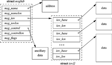
A variety of calls is available for sending and receiving data. The usual read (readv) and write (writev) system calls, as well as the newer send and recv calls, can be used with sockets that are in a connected state. Send and recv differ from the more common interface in that they both support an additional flags parameter. The flags can be used to peek at incoming data on reception (MSG_PEEK), to send or receive out-of-band data (MSG_OOB), and to send data without network routing (MSG_DONTROUTE). The sendto and recvfrom system calls have all the capabilities of send and recv and, in addition, permit callers to specify or receive the address of the peer with whom they are communicating; these calls are most useful for connectionless sockets, where the peer may vary on each message transmitted or received. (The send and recv calls were originally system calls; they are now implemented as library routines using sendto and recvfrom with null addresses.) Finally, the sendmsg and recvmsg system calls support the full interface to the interprocess-communication facilities. Besides scatter-gather operations being possible, an address may be specified or received, the optional flags described previously are available, and specially interpreted ancillary data or control information may be passed (see Fig. 11.1). Ancillary data may include protocol-specific data, such as addressing or options, and also specially interpreted data, called access rights.
Figure 11.1 Data structures for the sendmsg and recvmsg system calls.
In addition to these system calls, several other calls are provided to access miscellaneous services. The socketpair call provides a mechanism by which two connected sockets can be created without binding addresses. This facility is almost identical to a pipe, except for the potential for bidirectional flow of data; pipes are implemented internally as a pair of sockets. The getsockname call returns the locally bound address of a socket, whereas the getpeername call returns the address of the socket at the remote end of a connection. The shutdown call terminates data transmission or reception at a socket, and two ioctl -style calls—setsockopt and getsockopt—can be used to set and retrieve various parameters that control the operation of a socket or of the underlying network protocols. These options include the ability to transmit broadcast messages, to set the size of a socket’s send and receive data buffers, and to await the transmission of queued data when a socket is destroyed. Sockets are discarded with the normal close system call.
The interface to the interprocess-communication facilities was purposely designed to be orthogonal to the existing standard system interfaces—that is, to the open, read, and write system calls. This decision was made to avoid overloading the familiar interface with undue complexity. In addition, the developers thought that using an interface that was completely independent of the filesystem would improve the portability of software, because, for example, pathnames would not be involved. Backward compatibility, for the sake of naive processes, was still deemed important; thus, the familiar read–write interface was augmented to permit access to the new communication facilities wherever that made sense (e.g., when connected stream sockets were used).
11.2 Implementation Structure and Overview
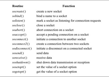
The interprocess-communication facilities are layered on top of the networking facilities, as shown in Fig. 11.2. Data flows from the application through the socket layer to the networking support, and vice versa. State required by the socket level is fully encapsulated in the socket layer, whereas any protocol-related state is maintained in auxiliary data structures that are specific to the supporting protocols. Responsibility for storage associated with transmitted data is passed from the socket level to the network level. Consistent adherence to this rule assists in simplifying details of storage management. Within the socket layer, the socket data structure is the focus of all activity. The system-call interface routines manage the actions related to a system call, collecting the system-call parameters (see Section 3.2) and converting user data into the format expected by the second-level routines. Most of the socket abstraction is implemented within the second-level routines. All second-level routines have names with a so prefix, and directly manipulate socket data structures and manage the synchronization between asynchronous activities; these routines are listed in Table 11.1.
The remainder of this chapter focuses on the implementation of the socket layer. Section 11.3 discusses how memory is managed at the socket level and below in the networking subsystem; Section 11.4 covers the socket and related data structures; Section 11.5 presents the algorithms for connection setup; Section 11.6 discusses data transfer; and Section 11.7 describes connection shutdown. Throughout this chapter, references to the supporting facilities provided by the network-communication protocols are made with little elaboration; a complete description of the interaction between the network protocols and the socket layer appears in Chapter 12, and the internals of the network protocols are presented in Chapter 13.
Figure 11.2 Interprocess-communication implementation layering. The boxes on the left name the standard layers; the boxes on the right name specific examples of the layers that might be used by an individual socket.

Table 11.1 Socket-layer support routines.
11.3 Memory Management
The requirements placed on a memory-management scheme by interprocess-communication and network protocols tend to be substantially different from those of other parts of the operating system. Although all require the efficient allocation and reclamation of memory, communication protocols in particular need memory in widely varying sizes. Memory is needed for variable-sized structures such as communication protocol packets. Protocol implementations must frequently prepend headers or remove headers from packetized data. As packets are sent and received, buffered data may need to be divided into packets, and received packets may be combined into a single record. In addition, packets and other data objects must be queued when awaiting transmission or reception. A special-purpose memory-management facility was created for use by the interprocess-communication and networking systems to address these needs.
Mbufs
The memory-management facilities revolve around a data structure called an mbuf (see Fig. 11.3 on page 370). Mbufs, or memory buffers, are 128 bytes long, with 100 or 108 bytes of this space reserved for data storage. For large messages, the system can associate larger sections of data with an mbuf by referencing an external mbuf cluster from a private virtual memory area. The size of an mbuf cluster may vary by architecture, and is specified by the macro MCLBYTES (traditionally 1 Kbyte).
Figure 11.3 Memory-buffer (mbuf) data structure.
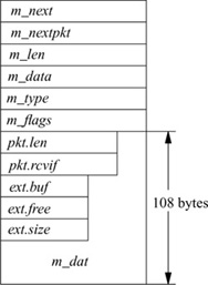
There are three sets of header fields that might be present in an mbuf. The first set is always present and resides at the beginning of the mbuf structure. The second set of header fields is optional. The third set of header fields is used when an external mbuf cluster is associated with an mbuf.
Data are stored either in the internal data area or in the external cluster, but never in both. Data in either location are accessed via a data pointer within the mbuf, and thus may begin at a location other than the beginning of the buffer area. In addition to the data-pointer field used to reference the data associated with an mbuf, a length field also is maintained. The length field shows the number of bytes of valid data to be found at the data-pointer location. The data and length fields allow routines to trim data efficiently at the start or end of an mbuf. In deletion of data at the start of an mbuf, the pointer is incremented and the length is decremented. In deletion of data at the end of an mbuf, only the length is decremented. When space is available within an mbuf, data can be added at either end. This flexibility to add and delete space without copying is particularly useful in communication-protocol implementation. Protocols routinely strip protocol information off the front or back of a message before the message’s contents are handed to a higher-level processing module, or add protocol information as a message is passed to lower levels.
The ability to refer to mbuf clusters from an mbuf permits data to be copied without a memory-to-memory copy operation. When multiple copies of a block of data are required, the same mbuf cluster can be referenced from multiple mbufs to avoid physical copies. An array of reference counts is maintained for a virtual array of mbuf clusters to support this style of sharing (see the next subsection).
Multiple mbufs can be linked to hold an arbitrary quantity of data. This linkage is done with the m_next field of the mbuf. By convention, a chain of mbufs linked in this way is treated as a single object. For example, the communication protocols build packets from chains of mbufs. A second field, m_nextpkt, links objects built from chains of mbufs into lists of objects. (This field was previously known as m_act.) Throughout our discussions, a collection of mbufs linked together with the m_next field will be called a chain; chains of mbufs linked together with the m_nextpkt field will be called a queue.
The mbuf structure also contains a type field. Each mbuf is typed according to its use. The mbuf type serves two purposes. The only operational use of the type is to distinguish optional components of a message in an mbuf chain that is queued for reception on a socket data queue. Otherwise, the type information is used in maintaining statistics about storage use and, if there are problems, as an aid in tracking mbufs.
The final header component of the standard mbuf structure is the flags field. The flags are logically divided into two sets: flags that describe the usage of an individual mbuf and those that describe an object stored in an mbuf chain. The flags describing an mbuf specify whether the mbuf references external storage (M_EXT), whether the second set of header fields is present (M_PKTHDR), and whether the mbuf completes a record (M_EOR). A packet normally would be stored in an mbuf chain (of one or more mbufs) with the M_PKTHDR flag set on the first mbuf of the chain. The mbuf flags describing the packet would be set in the first mbuf and could include either the broadcast flag (M_BCAST) or the multicast flag (M_MCAST). The latter flags specify that a transmitted packet should be sent as a broadcast or multicast, respectively, or that a received packet was sent in that manner.
If the M_PKTHDR flag is set on an mbuf, the mbuf has a second set of header fields immediately following the standard header. This addition causes the mbuf data area to shrink from 108 bytes to 100 bytes. The second header is used on only the first mbuf of a chain. It includes two fields: the total length of the object in the mbuf chain, and, for received packets, a field that identifies the network interface on which the packet was received.
An mbuf that uses external storage is marked with the M_EXT flag. Here, a third header area overlays the internal data area of an mbuf. The fields in this header describe the external storage, including the start of the buffer and its size. A third field is designated to point to a routine to free the buffer, in theory allowing various types of buffers to be mapped by mbufs. In the current implementation, however, the free function is not used, and the external storage is assumed to be a standard mbuf cluster.
Mbufs have fixed-sized, rather than variable-sized, data areas for several reasons. First, the fixed size minimizes memory fragmentation. This consideration was important at the time the networking software was designed originally, as a targeted machine was the BBN C70, which had a 20-bit physical address space. Second, communication protocols are frequently required to prepend or append headers to existing data areas, to split data areas, or to trim data from the beginning or end of a data area. The mbuf facilities are designed to handle such changes without reallocation or copying whenever possible. Finally, the dtom () function, described in the subsection on mbuf utility routines later in this section, would be much more expensive if mbufs were not fixed in size. (Note, however, that the dtom () function is now deprecated.)
The mbuf structure has changed substantially since its initial design. The flags field and the two optional sets of header fields were added since 4.3BSD. In addition, the data pointer replaces a field used as an offset in the initial version of the mbuf. The use of an offset was not portable when the data referenced could be in an mbuf cluster. The addition of a flags field allowed the use of a flag indicating external storage; earlier versions tested the magnitude of the offset to see whether the data were in the internal mbuf data area. The addition of the broadcast flag allowed network-level protocols to know whether packets were received as link-level broadcasts, as was required for standards conformance.
The two new headers were designed to avoid redundant calculations of the size of an object, to make it easier to identify the incoming network interface of a received packet, and to generalize the use of external storage by an mbuf. The design has not been completely successful. The packet header contains only two fields (8 bytes), although we anticipated that a timestamp or other fields would be added. It is probably not worth the complexity of having a variable-sized header on an mbuf for the packet header; instead, those fields probably should have been included in all mbufs, even if they were not used. Also, as we noted, the header describing the external storage includes a pointer to a free function. The header file includes an unused sample macro to use that function, in theory allowing other types of external storage. However, the example is incorrect. The problem is that the code continues to use the array of mbuf-cluster reference counts, which is one for one with mbuf clusters. If an mbuf mapped some other external buffer, indexing into this array of reference counts would be incorrect. Rather than providing a function to free the buffer, the mbuf header should have a function to adjust the reference count, freeing the buffer when the final reference is removed.
Storage-Management Algorithms
The system allocates mbuf structures with the standard memory allocator, the malloc () function. Mbuf clusters are managed differently, via three central resources: a pool of pages allocated from the system memory allocator, a fixed-sized area of kernel virtual memory for mapping pages used for mbuf clusters, and an array of counters used in maintaining reference counts on mbuf clusters. A free list is maintained for mbuf clusters. When additional mbuf clusters are required, the system allocates a page of memory, maps the page into the reserved area of kernel virtual memory, and divides the page into one or more mbuf clusters, depending on the page size. The array of reference counts is large enough for every mbuf cluster that could be allocated within this area of virtual memory, and is one for one with the virtual array of clusters. When the system is booted, the mbuf-allocation routines initialize the free list by allocating 4 Kbyte of physical memory for mbuf clusters. Further memory may be allocated as the system operates, up to a compile-time configurable limit (256 Kbyte by default, or 512 Kbyte if the GATEWAY configuration option is enabled). Once memory is allocated for mbuf clusters, it is never freed.
Mbuf-allocation requests indicate either that they must be fulfilled immediately or that they can wait for available resources. If a request is marked as “can wait” and the requested resources are unavailable, the process is put to sleep to aw ait available resources. The nonblocking allocation request is necessary for code that executes at interrupt level. If mbuf allocation has reached its limit or kernel memory is unavailable, the mbuf-allocation routines ask the network-protocol modules to give back any available resources that they can spare. A nonblocking request will fail if no resources are available.
An mbuf-allocation request is made through a call to m_get (), m_gethdr (), or through an equivalent macro used for efficiency purposes. Space for the mbuf is allocated by the malloc () function and is then initialized. For m_gethdr (), the mbuf is initialized with the optional packet header. The MCLGET macro adds an mbuf cluster to an mbuf.
Release of mbuf resources is straightforward; m_free () frees a single mbuf, and m_freem () frees a chain of mbufs. When an mbuf that references an mbuf cluster is freed, the reference count for the cluster is decremented. Mbuf clusters are placed onto the free list when their reference counts reach zero.
Mbuf Utility Routines
Many useful utility routines exist for manipulating mbufs within the kernel networking subsystem. Those routines that will be used in Chapter 12 are described briefly here.
The m_copym () routine makes a copy of an mbuf chain starting at a logical offset, in bytes, from the start of the data. This routine may be used to copy all or only part of a chain of mbufs. If an mbuf is associated with an mbuf cluster, the copy will reference the same data by incrementing the reference count on the cluster; otherwise, the data portion is copied as well. The m_copydata () function is similar, but copies data from an mbuf chain into a caller-provided buffer.
The m_adj () routine adjusts the data in an mbuf chain by a specified number of bytes, shaving data off either the front or back. No data are ever copied; m_adj() operates purely by manipulating the offset and length fields in the mbuf structures.
The mtod () macro takes a pointer to an mbuf header and a data type and returns a pointer to the data in the buffer, cast to the given type. The dtom () function is the inverse: It takes a pointer to an arbitrary address in the data of an mbuf, and returns a pointer to the mbuf header (rather than to the head of the mbuf chain). This operation is done through simple truncation of the data address to an mbuf-sized boundary. This function works only when data reside within the mbuf. In part because this restriction may force extra data copies, this function has been deprecated; it is no longer used in the main code paths of the network.
The m_pullup () routine rearranges an mbuf chain such that a specified number of bytes of data resides in a contiguous data area within the mbuf (not in external storage). This operation is used so that objects such as protocol headers are contiguous and can be treated as normal data structures, and so that dtom () will work when the object is freed. (If the dtom () macro is eventually removed, m_pullup() will no longer be forced to move data from mbuf clusters.) If there is room, m_pullup () will increase the size of the contiguous region up to the maximum size of a protocol header in an attempt to avoid being called in the future.
The M_PREPEND () macro adjusts an mbuf chain to prepend a specified number of bytes of data. If possible, space is made in place, but an additional mbuf may have to be allocated at the beginning of the chain. It is not currently possible to prepend data within an mbuf cluster because different mbufs might refer to data in different portions of the cluster.
11.4 Data Structures
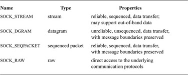
Sockets are the basic objects used by communicating processes. A socket’s type defines the basic set of communication semantics, whereas the communication domain defines auxiliary properties important to the use of the socket, and may refine the set of available communication semantics. Table 11.2 shows the four types of sockets currently supported by the system. To create a new socket, applications must specify the socket type and communication domain in which the socket is to be created. The request may also indicate a specific network protocol to be used by the socket. If no protocol is specified, the system selects an appropriate protocol from the set of protocols supported by the communication domain. If the communication domain is unable to support the type of socket requested (i.e., no suitable protocol is available), the request will fail.
Sockets are described by a socket data structure that is dynamically created at the time of a socket system call. Communication domains are described by a domain data structure that is statically defined within the system based on the system’s configuration (see Section 14.5). Communication protocols within a domain are described by a protosw structure that is also statically defined within the system for each protocol implementation configured. When a request is made to create a socket, the system uses the value of the communication domain to search linearly the list of configured domains. If the domain is found, the domain’s table of supported protocols is consulted for a protocol appropriate for the type of socket being created or for a specific protocol requested. (A wildcard entry may exist for a raw socket.) Should multiple protocol entries satisfy the request, the first is selected. We shall begin discussion of the data structures by examining the domain structure. The protosw structure is discussed in Section 12.1.
Table 11.2 Socket types supported by the system.
Communication Domains
The domain structure is shown in Fig. 11.4. The dom_name field is the ASCII name of the communication domain. (In the original design, communication domains were to be specified with ASCII strings; they are now specified with manifest constants.) The dom_family field identifies the protocol family used by the domain; possible values are shown in Table 11.3 (on page 376). Protocol families refer to the suite of communication protocols of a domain used to support the communication semantics of a socket. A protocol family generally has an associated address family defining an addressing structure, although it can use other addressing formats. The dom_protosw field points to the table of protocols supported by the communication domain, and the dom_NPROT OSW pointer marks the end of the table. The remaining entries contain pointers to domain-specific routines used in the management and transfer of access rights (described in Section 11.6) and fields relating to routing initialization for the domain.
Figure 11.4 Communication-domain data structure.


Sockets
The socket data structure is shown in Fig. 11.5. Storage for the socket structure is allocated dynamically via the malloc () routine. Sockets contain information about their type, the supporting protocol in use, and their state (Table 11.4). Data being transmitted or received are queued at the socket as a list of mbuf chains. Various fields are present for managing queues of sockets created during connection establishment. Each socket structure also holds a process-group identifier. The process-group identifier is used in delivering the SIGURG and SIGIO signals; SIGURG is sent when an urgent condition exists for a socket, and SIGIO is used by the asynchronous I/O facility (see Section 6.4). The socket contains an error field, which is needed for storing asynchronous errors to be reported to the owner of the socket.
Sockets are located through a process’s file descriptor via the file table. When a socket is created, the f_data field of the file structure is set to point at the socket structure, and the f_ops field to point to the set of routines defining socket-specific file operations. In this sense, the socket structure is a direct parallel of the vnode structure used by the filesystems.
Figure 11.5 Socket data structure.
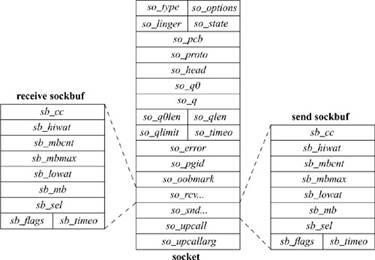
The socket structure acts as a queueing point for data being transmitted and received. As data enter the system as a result of system calls, such as write or send, the socket layer passes the data to the networking subsystem as a chain of mbufs for immediate transmission. If the supporting protocol module decides to postpone transmission of the data, or if a copy of the data is to be maintained until an acknowledgment is received, the data are queued in the socket’s transmit buffer. When the network has consumed the data, it discards them from the outgoing queue. On reception, the network passes data up to the socket layer, also in mbuf chains, where they are then queued until the application makes a system call to request them. The socket layer can also make an upcall to an internal kernel client of the network when data arrive, allowing the data to be processed without a context switch. Upcalls are used by the NFS server (see Chapter 9).
Table 11.4 Socket states.

To avoid resource exhaustion, sockets impose upper bounds on the number of bytes of data that can be queued in a socket data buffer, and also on the amount of storage space that can be used for data. This high watermark is initially set by the protocol, although an application can change the value up to a system maximum, normally 256 Kbyte. The network protocols can examine the high watermark and use the value in flow-control policies. A low watermark also is present in each socket data buffer. The low watermark allows applications to control data flow by specifying a minimum number of bytes required to satisfy a reception request, with a default of 1 byte and a maximum of the high watermark. For output, the low watermark sets the minimum amount of space available before transmission can be attempted; the default is the size of an mbuf cluster. These values also control the operation of the select system call when it is used to test for ability to read or write the socket.
When connection indications are received at the communication-protocol level, the connection may require further processing to complete. Depending on the protocol, that processing may be done before the connection is returned to the listening process, or the listening process may be allowed to confirm or reject the connection request. Sockets used to accept incoming connection requests maintain two queues of sockets associated with connection requests. The list of sockets headed by the so_q0 field represents a queue of connections that must be completed at the protocol level before being returned. The so_q field heads a list of sockets that are ready to be returned to the listening process. Like the data queues, the queues of connections also have an application-controllable limit. The limit applies to both queues. Because the limit may include sockets that cannot yet be accepted, the system enforces a limit 50-percent larger than the nominal limit.
Note that, although a connection may be established by the network protocol, the application may choose not to accept the established connection, or may close down the connection immediately after discovering the identity of the client. It is also possible for a network protocol to delay completion of a connection until after the application has obtained control with the accept system call. The application might then accept or reject the connection explicitly with a protocol-specific mechanism. Otherwise, if the application does a data transfer, the connection is confirmed; if the application closes the socket immediately, the connection is rejected.
Socket Addresses
Sockets may be labeled so that peers can connect to them. The socket layer treats an address as an opaque object. Applications supply and receive addresses as tagged, variable-length byte strings. Addresses are placed in mbufs within the socket layer. A structure called a sockaddr, shown in Fig. 11.6, may be used as a template for referring to the identifying tag and length of each address. Most protocol layers support a single address type as identified by the tag, known as the address family. In general, the address-family values are one-for-one with protocol family values.
Figure 11.6 Socket-address template structure.
![]()
It is common for addresses passed in by an application to reside in mbufs only long enough for the socket layer to pass them to the supporting protocol for transfer into a fixed-sized address structure, for example, when a protocol records an address in a protocol state block. The sockaddr structure is the common means by which the socket layer and network-support facilities exchange addresses. The size of the generic data array was chosen to be large enough to hold many addresses directly, although generic code cannot depend on having sufficient space in a sockaddr structure for an arbitrary address. The local communication domain (formerly known as the UNIX domain), for example, stores filesystem pathnames in mbufs and allows socket names as large as 104 bytes, as shown in Fig. 11.7. The Internet communication domain, on the other hand, uses a fixed-size structure that combines a DARPA Internet address and a port number. The Internet protocols reserve space for addresses in an Internet control-block data structure, and free up mbufs that contain addresses after copying the addresses. The ISO (OSI) domain uses a variable-sized structure with a fixed-size initial component. The initial portion has space for a network-level address plus a local transport selector.
Figure 11.7 Network system, Internet, and local-domain address structures.
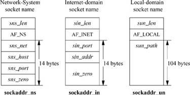
A larger space may be needed for larger transport selectors or for higher-level selectors. Another example of a variable-length structure is the link-layer address format, which includes an optional network interface name as a string, an optional interface index, and an optional link-layer address.
11.5 Connection Setup
For two processes to pass information between them, an association must be established. The steps involved in creating an association (socket, connect, listen, accept, etc.) were described in Section 11.1. In this section, we shall study the operation of the socket layer in establishing associations. As the state associated with a connectionless transfer of data is fully encapsulated in each message that is sent, our discussion will focus on connection-based associations established with the connect, listen, and accept system calls.
Connection establishment in the client–server model is asymmetric. A client process actively initiates a connection to obtain service, whereas a server process passively accepts connections to provide service. Fig. 11.8 shows the state-transition diagram for a socket used to initiate or accept connections. State transitions are initiated either by user actions (i.e., system calls) or by protocol actions that result from receiving network messages or servicing timers that expire.
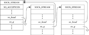
Sockets are normally used to send and receive data. When they are used in establishing a connection, they are treated somewhat differently. If a socket is to be used to accept a connection, a listen system call must be used. The listen call invokes solisten (), which notifies the supporting protocol that the socket will be receiving connections, establishes an empty list of pending connections at the socket (through the so_q field), and then marks the socket as accepting connections, SO_ACCEPTCON. At the time a listen is done, a backlog parameter is specified by the application. This parameter sets a limit on the number of incoming connections that the system will queue awaiting acceptance by the application. (The system enforces a maximum on this limit.) Once a socket is set up to receive connections, the remainder of the work in creating connections is managed by the protocol layers. For each connection established at the server side, a new socket is created with the sonewconn1 () routine. These new sockets may be placed on the socket’s queue of partially established connections while the connections are being completed, or they may be placed directly into the queue of connections ready to be passed to the application via the accept call. The new sockets might be ready to be passed to the application either because no further protocol action is necessary to establish the connection, or because the protocol allows the listening process to confirm or reject the connection request. In the latter case, the socket is marked as confirming (state bit SS_CONFIRMING), so that the pending connection request will be confirmed or rejected as needed. Once sockets on the queue of partly established connections are ready, they are moved to the queue of connections completed and pending acceptance by an application (see Fig. 11.9). When an accept system call is made to obtain a connection, the system verifies that a connection is present on the socket’s queue of ready connections. If no connection is ready to be returned, the system puts the process to sleep until one arrives (unless nonblocking I/O is being used with the socket, in which case an error is returned). When a connection is available, the associated socket is removed from the queue, a new file descriptor is allocated to reference the socket, and the result is returned to the caller. If the accept call indicates that the peer’s identity is to be returned, the peer’s address is obtained from the protocol layer and is copied into the supplied buffer.
Figure 11.8 Socket state transitions during process rendezvous.
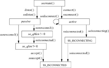
Figure 11.9 Connections queued at a socket awaiting an accept call.
On the client side, an application requests a connection with the connect system call, supplying the address of the peer socket to which to connect. The system verifies that a connection attempt is not already in progress for that socket, then invokes soconnect () to initiate the connection. The soconnect () routine first checks the socket to see whether the latter is already connected. If the socket is already connected, the existing connection is first terminated (this disconnection is done with datagram sockets only). With the socket in an unconnected state, soconnect() then marks the state as connecting, and makes a request to the protocol layer to initiate the new connection. Once the connection request has been passed to the protocol layer, if the connection request is incomplete, the system puts the process to sleep to await notification by the protocol layer that a completed connection exists. A nonblocking connect may return at this point, but a process awaiting a completed connection will awaken only when the connection request has been completed—either successfully or with an error condition.
A socket’s state during connection establishment is managed jointly by the socket layer and the supporting protocol layer. The socket’s state value is never altered directly by a protocol; to promote modularity, all modifications are performed by surrogate socket-layer routines, such as soisconnected (). These routines modify the socket state as indicated and notify any waiting processes. The supporting protocol layers never use process synchronization or signaling facilities directly. Errors that are detected asynchronously are communicated to a socket in its so_error field. For example, if a connection request fails because the protocol layer detects that the requested service is unavailable, the so_error field usually is set to ECONNREFUSED before the requesting process is awakened. The socket layer always inspects the value of so_error on return from a call to tsleep (); this field is used to report errors detected asynchronously by the protocol layers.
11.6 Data Transfer
Most of the work done by the socket layer lies in sending and receiving data. Note that the socket layer itself explicitly refrains from imposing any structure on data transmitted or received via sockets other than optional record boundaries. This policy is in contrast to that of other interprocess-communication facilities [Fitzgerald & Rashid, 1986]. Within the overall interprocess-communication model, any data interpretation or structuring is logically isolated in the implementation of the communication domain. An example of this logical isolation is the ability to pass file descriptors between processes using local-domain sockets.
Sending and receiving of data can be done with any one of several system calls. The system calls vary according to the amount of information to be transmitted and received, and according to the state of the socket doing the operation. For example, the write system call may be used with a socket that is in a connected state, as the destination of the data is implicitly specified by the connection; but the sendto or sendmsg system calls allow the process to specify the destination for a message explicitly. Likewise, when data are received, the read system call allows a process to receive data on a connected socket without receiving the sender’s address; the recvfrom and recvmsg system calls allow the process to retrieve the incoming message and the sender’s address. The recvmsg and sendmsg system calls allow scatter-gather I/O with multiple user-provided buffers. In addition, recvmsg reports additional information about a received message, such as whether it was expedited (out of band), whether it completes a record, or whether it was truncated because a buffer was too small. The decision to provide many different system calls, rather than to provide only a single general interface, is debatable. It would have been possible to implement a single system-call interface and to provide simplified interfaces to applications via user-level library routines. However, the single system call would have to be the most general call, which has somewhat higher overhead. Internally, all transmission and reception requests are converted to a uniform format and are passed to the socket-layer sendit() and recvit () routines, respectively.
Transmitting Data
The sendit () routine is responsible for gathering all system-call parameters that the application has specified into the kernel’s address space (except the actual data), and then for invoking the sosend () routine to do the transmission. The parameters may include the following components, illustrated in Fig. 11.1:
• An address to which data will be sent, if the socket has not been connected
• Optional ancillary data (control data) associated with the message; ancillary data can include protocol-specific data associated with a message, protocol option information, or access rights
• Normal data, specified as an array of buffers (see Section 6.4)
• Optional flags, including out-of-band and end-of-record flags
The sosend () routine handles most of the socket-level data-transmission options, including requests for transmission of out-of-band data and for transmission without network routing. This routine is also responsible for checking socket state—for example, seeing whether a required connection has been made, whether transmission is still possible on the socket, and whether a pending error should be reported rather than transmission attempted. In addition, sosend () is responsible for putting processes to sleep when their data transmissions exceed the buffering available in the socket’s send buffer. The actual transmission of data is done by the supporting communication protocol; sosend () copies data from the user’s address space into mbufs in the kernel’s address space, and then makes calls to the protocol to transfer the data.
Most of the work done by sosend () lies in checking the socket state, handling flow control, checking for termination conditions, and breaking up an application’s transmission request into one or more protocol transmission requests. The request must be broken up only when the size of the user’s request plus the number of data queued in the socket’s send data buffer exceeds the socket’s high watermark. It is not permissible to break up a request if the protocol is atomic, because each request made by the socket layer to the protocol modules implicitly indicates a boundary in the data stream. Most datagram protocols are of this type. Honoring each socket’s high watermark ensures that a protocol will always have space in the socket’s send buffer to enqueue unacknowledged data. It also ensures that no process, or group of processes, can monopolize system resources.
For sockets that guarantee reliable data delivery, a protocol will normally maintain a copy of all transmitted data in the socket’s send queue until receipt is acknowledged by the receiver. Protocols that provide no assurance of delivery normally accept data from sosend () and directly transmit the data to the destination without keeping a copy. But sosend () itself does not distinguish between reliable and unreliable delivery.
Sosend() always ensures that a socket’s send buffer has enough space available to store the next section of data to be transmitted. If a socket has insufficient space in its send buffer to hold all the data to be transmitted, sosend () uses the following strategy. If the protocol is atomic, sosend () verifies that the message is no larger than the send buffer size; if the message is larger, it returns an EMSGSIZE error. If the available space in the send queue is less then the send low watermark, the transmission is deferred; if the process is not using nonblocking I/O, the process is put to sleep until more space is available in the send buffer; otherwise, an error is returned. When space is available, a protocol transmit request is formulated according to the available space in the send buffer. Sosend () copies data from the user’s address space into mbuf clusters whenever the data would fill more than two mbufs, on the theory that two allocations are required for an mbuf plus a cluster. If a transmission request for a nonatomic protocol is large, each protocol transmit request will normally contain a full mbuf cluster. Although additional data could be appended to the mbuf chain before delivery to the protocol, it is preferable to pass the data to lower levels immediately. This strategy allows better pipelining, as data reach the bottom of the protocol stack earlier, and can begin physical transmission sooner. This procedure is repeated until insufficient space remains; it resumes each time that additional space becomes available.
This strategy tends to preserve the application-specified message size and helps to avoid fragmentation at the network level. The latter benefit is important, because system performance is significantly improved when data-transmission units are large, e.g. the mbuf cluster size.
The sosend () routine, in manipulating a socket’s send data buffer, takes care to ensure that access to the buffer is synchronized among multiple sending processes. It does so by bracketing accesses to the data structure with calls to sblock() and sbunlock (). Interlocking against asynchronous network activity is also a concern here, as the network-protocol modules that operate at network-interrupt level cannot wait for access to a data structure such as a socket data buffer. Thus, they do not honor the locking protocol used between processes. To block network-protocol modules, sosend () must raise the processor priority level to splnet to ensure that no protocol processing takes place that might alter the state of a socket being manipulated while it is testing that state.
Receiving Data
The soreceive () routine receives data queued at a socket. As the counterpart to sosend(), soreceive () appears at the same level in the internal software structure and does similar tasks. Three types of data may be queued for reception at a socket: in-band data, out-of-band data, and ancillary data such as access rights. In-band data may also be tagged with the sender’s address. Handling of out-of-band data varies by protocol. They may be placed at the beginning of the receive buffer, may be placed at the end of the buffer to appear in order with other data, or may be managed in the protocol layer separate from the socket’s receive buffer. In the first two cases, they are returned by normal receive operations. In the final case, they are retrieved through a special interface when requested by the user. These options allow varying styles of urgent data transmission.
Soreceive() checks the socket’s state, including the received data buffer, for incoming data, errors, or state transitions, and processes queued data according to their type and the actions specified by the caller. A system-call request may specify that only out-of-band data should be retrieved (MSG_OOB), or that data should be returned but not removed from the data buffer (by specifying the MSG_PEEK flag). Receive calls normally return as soon as the low watermark is reached; thus, by default, the call returns when any data are present. The MSG_WAITALL flag specifies that the call should block until it can return all the requested data if possible. On the other hand, the MSG_DONTWAIT flag causes the call to act as though the socket was in nonblocking mode, returning EWOULDBLOCK rather than blocking.
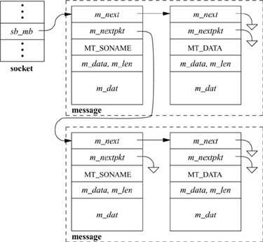
Data present in the receive data buffer are organized in one of several ways, depending on whether message boundaries are preserved. There are three common cases, for stream, datagram, and sequenced-packet sockets. In the general case, the receive data buffer is organized as a list of messages (see Fig. 11.10 on page 386). Each message can include a sender’s address (for datagram protocols), ancillary data, and normal data. Depending on the protocol, it is also possible for expedited or out-of-band data to be placed into the normal receive buffer. Each mbuf chain on a list represents a single message or, for the final chain, a possibly incomplete record. Protocols that supply the sender’s address with each message place a single mbuf containing the address at the front of message. Immediately following any address is an optional mbuf containing any ancillary data. Regular data mbufs follow the ancillary data. Names and ancillary data are distinguished by the type field in an mbuf; addresses are marked as MT_SONAME, whereas ancillary data are tagged as MT_CONTROL. Each message other than the final one is considered to be terminated. The final message is terminated implicitly when an atomic protocol is used, such as most datagram protocols. Sequenced packet protocols could treat each message as an atomic record, or they could support records that could be arbitrarily long (as is done in OSI). In the latter case, the final record in the buffer might or might not be complete, and a flag on the final mbuf, M_EOR, marks the termination of a record. Record boundaries (if any) are generally ignored by a stream protocol. However, transition from out-of-band data to normal data in the buffer, or presence of ancillary data, causes logical boundaries. A single receive operation never returns data that cross a logical boundary. Note that the storage scheme used by sockets allows them to compact data of the same type into the minimal number of mbufs required to hold those data.
Figure 11.10 Data queueing for datagram socket.
On entry to soreceive (), a check is made to see whether out-of-band data are being requested. If they are, the protocol layer is queried to see whether any such data are available; if the data are available, they are returned to the caller. As regular data cannot be retrieved simultaneously with out-of-band data, soreceive () then returns. Otherwise, data from the normal queue have been requested. The soreceive() function first checks whether the socket is in confirming state, with the peer awaiting confirmation of a connection request. If it is, no data can arrive until the connection is confirmed, and the protocol layer is notified that the connection should be completed. Soreceive () then checks the receive-data-buffer character count to see whether data are available. If they are, the call returns with at least the data currently available. If no data are present, soreceive () consults the socket’s state to find out whether data might be forthcoming. Data may no longer be received because the socket is disconnected (and a connection is required to receive data), or because the reception of data has been terminated with a shutdown by the socket’s peer. In addition, if an error from a previous operation was detected asynchronously, the error needs to be returned to the user; soreceive() checks the so_error field after checking for data. If no data or error exists, data might still arrive, and if the socket is not marked for nonblocking I/O, soreceive() puts the process to sleep to await the arrival of new data.
When data arrive for a socket, the supporting protocol notifies the socket layer by calling sorwakeup(). Soreceive() can then process the contents of the receive buffer, observing the data-structuring rules described previously. Soreceive () first removes any address that must be present, then optional ancillary data, and finally normal data. If the application has provided a buffer for the receipt of ancillary data, they are passed to the application in that buffer; otherwise, they are discarded. The removal of data is slightly complicated by the interaction between in-band and out-of-band data managed by the protocol. The location of the next out-of-band datum can be marked in the in-band data stream and used as a record boundary during in-band data processing. That is, when an indication of out-of-band data is received by a protocol that holds out-of-band data separately from the normal buffer, the corresponding point in the in-band data stream is marked. Then, when a request is made to receive in-band data, only data up to the mark will be returned. This mark allows applications to synchronize the in-band and out-of-band data streams, so that, for example, received data can be flushed up to the point at which out-of-band data are received. Each socket has a field, so_oobmark, that contains the character offset from the front of the receive data buffer to the point in the data stream at which the last out-of-band message was received. When in-band data are removed from the receive buffer, the offset is updated, so that data past the mark will not be mixed with data preceding the mark. The SS_RCVATMARK bit in a socket’s state field is set when so_oobmark reaches zero to show that the out-of-band data mark is at the beginning of the socket receive buffer. An application can test the state of this bit with the SIOCATMARK ioctl call to find out whether all in-band data have been read up to the point of the mark.
Once data have been removed from a socket’s receive buffer, soreceive () updates the state of the socket and notifies the protocol layer that data have been received by the user. The protocol layer can use this information to release internal resources, to trigger end-to-end acknowledgment of data reception, to update flow-control information, or to start a new data transfer. Finally, if any access rights were received as ancillary data, soreceive () passes them to a communication-domain−specific routine to convert them from their internal representation to the external representation.
The soreceive () function returns a set of flags that are supplied to the caller of the recvmsg system call via the msg_flags field of the msghdr structure (see Fig. 11.1). The possible flags include MSG_EOR to specify that the received data complete a record for a nonatomic sequenced packet protocol, MSG_OOB to specify that expedited (out-of-band) data were received from the normal socket receive buffer, MSG_TRUNC to specify that an atomic record was truncated because the supplied buffer was too small, and MSG_CTRUNC to specify that ancillary data were truncated because the control buffer was too small.
Passing Access Rights
In addition to the transmission and reception of uninterpreted data, the system also supports the passage of typed ancillary data that have special meaning, either to a protocol layer or to an application. Access rights are one such type of ancillary data. These data normally represent the right to do operations on associated objects. The data used to represent access rights, or capabilities, normally are meaningful only within the context of the process that created or obtained the right; thus, their transmission requires system support to make them meaningful in a receiving process’s context. For example, in 4.4BSD, access rights to files in the filesystem or sockets are encapsulated as file descriptors. A file descriptor is a small integer number that is meaningful only in the context of the process that opened or created the associated file. To pass a file descriptor from one process to another, the system must create a reference to the associated file-table structure in the receiving process’s user structure.
Access rights, or capabilities, are categorized as internalized or externalized. Internalized capabilities require the support of trusted agents to be useful. Ke ys associated with these capabilities are created by a trusted agent, and, when presented for accessing a protected object, are deemed valid according to their interpretation in the context of the presenter.
Externalized capabilities, on the other hand, use keys that require no specific trusted agent for their use. That is, the validation of the right to access an object is based solely on the possession and presentation of the requisite key. Systems that use externalized capabilities frequently use a public-key encryption algorithm. Ke ys for externalized capabilities normally have the properties that they are long lived and that they may be stored in locations such as a filesystem without losing their usefulness.
No specific system support is required to support externalized capabilities. To support internalized capabilities, however, the operating system, acting as a trusted agent, must verify and translate keys when transmitting them as messages between processes. The interprocess-communication system provides facilities, on a per-communication domain basis, to process all access rights transmitted and received in messages, and to dispose of rights that are not received.
Sending and receiving of access rights requires the internalization and externalization of these rights. Internalization converts a key held by a sending process into an internal form that can be passed as data in a message. Externalization reverses this process, converting the internal form into an external form that is meaningful in the context of the receiving process. Internalization of access rights is done at the protocol layer when the sosend () routine requests transmission of data containing access rights. The access rights to be transmitted are passed as an mbuf chain separate from the regular data. When soreceive () encounters access rights on the receive data queue, it invokes the communication domain’s dom_externalize routine to externalize the rights. The socket layer implicitly presumes that access rights stored in socket data queues will be valid as long as the system remains up. That is, there are no mechanisms to expedite the delivery of access rights, or to time out or invalidate rights stored on a socket data queue.
Passing Access Rights in the Local Domain
In the local domain, the internalization of file descriptors results in their conversion to system file-table pointers, whereas externalization requires allocation of new file descriptors for the receiving process. File descriptors passed in messages are really duplicates of the ones held by the sending process (as though they had been created by dup). The sending process must explicitly close a file descriptor after that descriptor has been sent to give the descriptor away.
A garbage-collection facility is provided to reclaim resources associated with access rights that are not delivered properly. Access rights may not be delivered for several reasons: because the receiving socket has insufficient space, because the user does not request them with the proper system call when receiving data from the socket, or because the socket is closed while access rights are still present in the receive buffer. In addition, it is possible for access rights in a socket receive buffer to become inaccessible because the socket itself is not accessible. For example, if a socket pair is created, each socket of the pair is sent as access rights on one of the sockets, and then both sockets are closed; then all the remaining references to the two sockets will be in access rights that can never be received. Garbage collection is used because of this problem, and because normal message processing does not permit a protocol to access a message after the protocol has passed on that message for delivery. This inability to access a message after it has been transmitted means that, if access rights in a message are not delivered, these rights will be discarded without being reclaimed. In the local domain, reclamation of access rights ensures that files associated with these rights are closed, so that system resources, such as file-table entries, are not depleted.
For garbage collection to be implemented, each file-table entry must contain a count of references held by file descriptors present in socket receive queues, f_msgcount. Another variable, unp_rights, tracks the number of file descriptors held in all the local-domain sockets in use. When a file descriptor is internalized to a file-table pointer for transmission, the f_msgcount for the file is incremented. On reception, when the file descriptor is externalized, f_msgcount is decremented. When a local-domain socket is reclaimed and unp_rights is nonzero, the garbage-collection routine, unp_gc (), is invoked to scan the file table and all local-domain sockets to reclaim unaccounted-for file-table references.
Unp_gc() uses a mark-and-sweep algorithm in doing its duties [J. Cohen, 1981]. The basic strategy is to locate all references to files that are accessible and to mark them. Files in a process’s open file array have a reference not in a message, and are thus accessible. If the file is a socket that is accessible, access rights held in its receive buffer can be accessed once received, and thus the files to which they refer are marked as well.† This search is repeated while there are newly marked files whose buffers have not been scanned, accounting for sockets that are reachable only via receipt of access rights, which in turn contain other access rights. The garbage collector can then reclaim lost references by searching the file table for un marked entries for which all references are indicated as being in socket receive queues.
† If a listening socket is accessible, then any queued connections that it holds are also accessible; the garbage collector in 4.4BSD fails to take this fact into account.
Note that the garbage collector is invoked only when a local-domain socket is closed and file descriptors are known to be queued awaiting reception; thus, the overhead associated with the garbage collector is limited. Also, the garbage collector reclaims only those file-table entries that were lost while being passed in messages; references that might be lost in other parts of the system are not reclaimed.
11.7 Socket Shutdown
Although closing a socket and reclaiming its resources at first glance appears to be a straightforward operation, it can be complicated. The complexity arises because of the implicit semantics of the close system call. In certain situations (e.g., when a process exits), a close call is never expected to fail. However, when a socket promising reliable delivery of data is closed with data still queued for transmission or awaiting acknowledgment of reception, the socket must attempt to transmit the data, perhaps indefinitely, for the close call to maintain the socket’s advertised semantics. If the socket discards the queued data to allow the close to complete successfully, it violates its promise to deliver data reliably. Discarding data can cause naive processes, which depend on the implicit semantics of close, to work unreliably in a network environment. However, if sockets block until all data have been transmitted successfully, then, in some communication domains, a close may never complete!
The socket layer compromises in an effort to address this problem yet to maintain the semantics of the close system call. Figure 11.11 shows the possible state transitions for a socket from a connected to a closed state. In normal operation, closing a socket causes any queued but unaccepted connections to be discarded. If the socket is in a connected state, a disconnect is initiated. The socket is marked to indicate that a file descriptor is no longer referencing it, and the close operation returns successfully. When the disconnect request completes, the network support notifies the socket layer and the socket resources are reclaimed. The network layer may attempt to transmit any data queued in the socket’s send buffer, although there is no guarantee that it will. However, commonly used connection-oriented protocols generally attempt to transmit any queued data asynchronously after the close call returns, preserving the normal semantics of close on a file.
Figure 11.11 Socket-state transitions during shutdown.
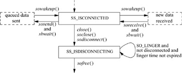
Alternatively, a socket may be marked explicitly to force the application process to linger when closing until pending data have drained and the connection has shut down. This option is marked in the socket data structure using the setsockopt system call with the SO_LINGER option. When an application indicates that a socket is to linger, it also specifies a duration for the lingering period. The application can then block for as long as the specified duration while waiting for pending data to drain. If the lingering period expires before the disconnect is completed, the socket layer then notifies the network that it is closing, possibly discarding any data still pending. Some protocols handle the linger option differently; in particular, if the linger option is set with a duration of zero, the protocol may discard pending data, rather than attempt to deliver them asynchronously.
Exercises
11.1 What limitation in the use of pipes inspired the developers to design alternative interprocess-communication facilities?
11.2 Why are the 4.4BSD interprocess-communication facilities designed to be independent of the filesystem for naming sockets?
11.3 Why is interprocess communication layered on top of networking in 4.4BSD, rather than the other way around?
11.4 Would a screen editor be considered a naive or a sophisticated program, according to the definitions given in this chapter? Explain your answer.
11.5 What are out-of-band data? What types of socket support the communication of out-of-band data? Describe one use for out-of-band data.
11.6 Give two requirements that interprocess communication places on a memory-management facility.
11.7 How many mbufs and mbuf clusters would be needed to hold a 3024-byte message? Draw a picture of the necessary mbuf chain and any associated mbuf clusters.
11.8 Why does an mbuf have two link pointers? For what is each pointer used?
11.9 Each socket’s send and receive data buffers have high and low watermarks. For what are these watermarks used?
11.10 Consider a socket with a network connection that is queued at the socket aw aiting an accept system call. Is this socket on the queue headed by the so_q or by the so_q0 field in the socket structure? What is the use of the queue that does not contain the socket?
11.11 Describe two types of protocols that would immediately place incoming connection requests into the queue headed by the so_q field in the socket structure.
11.12 How does the protocol layer communicate an asynchronous error to the socket layer?
11.13 Sockets explicitly refrain from interpreting the data that they send and receive. Do you believe that this approach is correct? Explain your answer.
11.14 Why does the sosend () routine ensure there is enough space in a socket’s send buffer before making a call to the protocol layer to transmit data?
11.15 How is the type information in each mbuf used in the queueing of data at a datagram socket? How is this information used in the queueing of data at a stream socket?
11.16 Why does the soreceive () routine optionally notify the protocol layer when data are removed from a socket’s receive buffer?
11.17 Describe an application where the ability to pass file descriptors is useful. Is there another way to simulate this facility in 4.4BSD?
11.18 What is the difference between an internalized capability and an externalized capability? Would file descriptors be considered externalized or internalized capabilities, according to the definitions given in this chapter?
11.19 What might cause a connection to linger forever when closing?
*11.20 What effect might storage compaction have on the performance of network-communication protocols?
**11.21 Why is releasing mbuf-cluster storage back to the system complicated? Explain why it might be desirable.
**11.22 In the original design of the interprocess-communication facilities, a reference to a communication domain was obtained with a domain system call,
int d; d = domain(“inet”);
(where d is a descriptor, much like a file descriptor), and sockets then were created with
                            s= socket(type, d, protocol);
                            int s, type, protocol;
What advantages and disadvantages does this scheme have compared to the one that is used in 4.4BSD? What effect does the introduction of a domain descriptor type have on the management and use of descriptors within the kernel?
References
Cerf, 1978.
V. Cerf, “The Catenet Model for Internetworking,” Technical Report IEN 48, SRI Network Information Center, Menlo Park, CA, July 1978.
D. Cohen, 1977.
D. Cohen, “Network Control Protocol (NCP) Software,” University of Illinois Software Distribution, University of Illinois, Champaign-Urbana, IL, 1977.
J. Cohen, 1981.
J. Cohen, “Garbage Collection of Linked Data Structures,” Computing Surveys, vol. 13, no. 3, p. 341−367, September 1981.
Fitzgerald & Rashid, 1986.
R. Fitzgerald & R. F. Rashid, “The Integration of Virtual Memory Management and Interprocess Communication in Accent,” ACM Transactions on Computer Systems, vol. 4, no. 2, p. 147−177, May 1986.
Gurwitz, 1981.
R. F. Gurwitz, “VAX-UNIX Networking Support Project—Implementation Description,” Technical Report IEN 168, SRI Network Information Center, Menlo Park, CA, January 1981.
Kalash et al, 1986.
J. Kalash, L. Rodgin, Z. Fong, & J. Anton, “Ingres Version 8 Reference Manual,” in UNIX Programmer’s Supplementary Documents, Volume 2, 4.3 Berkeley Software Distribution, Virtual VAX-11 Version, p. 10:1−88, USENIX Association, Berkeley, CA, 1986.
Rashid, 1980.
R. F. Rashid, “An Inter-Process Communication Facility for UNIX,” Technical Report, Carnegie-Mellon University, Pittsburgh, PA, August 14, 1980.
Sunshine, 1977.
C. Sunshine, “Interprocess Communication Extensions for the UNIX Operating System: Design Considerations,” Technical Report R-2064/1-AF, Rand Corporation, Santa Monica, CA, June 1977.
UPMV7, 1983.
UPMV7, UNIX Programmer’s Manual, Seventh ed, Volumes 1 and 2, Holt, Rinehart & Winston, New York, NY, 1983.