
Chapter 13
Network Protocols
Chapter 12 presented the network-communications architecture of 4.4BSD. In this chapter, we examine the network protocols implemented within this framework. The 4.4BSD system supports four major communication domains: DARPA Internet, Xerox Network Systems (NS), ISO/OSI, and local domain (formerly known as the UNIX domain). The local domain does not include network protocols because it operates entirely within a single system. The Internet protocol suite was the first set of protocols implemented within the network architecture of 4.2BSD. Following the release of 4.2BSD, several proprietary protocol families were implemented by vendors within the network architecture. However, it was not until the addition of the Xerox NS protocols in 4.3BSD that the system’s ability to support multiple network-protocol families was visibly demonstrated. Although some parts of the protocol interface were previously unused and thus unimplemented, the changes required to add a second network-protocol family did not substantially modify the network architecture. The implementation of the ISO OSI networking protocols, as well as other changing requirements, led to a further refinement of the network architecture in 4.4BSD.
In this chapter, we shall concentrate on the organization and implementation of the Internet protocols. This protocol implementation is used widely, both in 4BSD systems and in many other systems, because it was publicly available when many vendors were looking for tuned and reliable communication protocols. Developers have implemented other protocols, including Xerox NS and OSI, by following the same general framework set forth by the Internet protocol routines. After describing the overall architecture of the Internet protocols, we shall examine their operation according to the structure defined in Chapter 12. We shall also describe the significant algorithms used by the Internet protocols. We then shall discuss changes that the developers made in the system motivated by aspects of the OSI protocols and their implementation.
13.1 Internet Network Protocols
The Internet network protocols were developed under the sponsorship of DARPA, for use on the ARPANET [McQuillan & Walden, 1977; DARPA, 1983]. They are commonly known as TCP/IP, although TCP and IP are only two of the many protocols in the family. Unlike earlier protocols used within the ARPANET (the ARPANET Host-to-Host Protocol, sometimes called the Network Control Program (NCP)) [Carr et al, 1970], these protocols do not assume a reliable subnetwork that ensures delivery of data. Instead, the Internet protocols were devised for a model in which hosts were connected to networks with varying characteristics, and the networks were interconnected by routers (generally called gateways at the time). Such a model is called a catenet [Cerf, 1978]. The Internet protocols were designed for packet-switching networks ranging from the ARPANET or X.25, which provide reliable message delivery or notification of failure, to pure datagram networks such as Ethernet, which provide no indication of datagram delivery.
This model leads to the use of at least two protocol layers. One layer operates end to end between two hosts involved in a conversation. It is based on a lower-level protocol that operates on a hop-by-hop basis, forwarding each message through intermediate routers to the destination host. In general, there exists at least one protocol layer above the other two: it is the application layer. This three-level layering has been called the ARPANET Reference Model [Padlipsky, 1985]. The three layers correspond roughly to levels 3 (network), 4 (transport), and 7 (application) in the ISO Open Systems Interconnection reference model [ISO, 1984].
The Internet communications protocols that support this model have the layering illustrated in Fig. 13.1. The Internet Protocol (IP) is the lowest-level protocol in the ARPANET Reference Model; this level corresponds to the ISO network layer. IP operates hop by hop as a datagram is sent from the originating host to the destination via any intermediate routers. It provides the network-level services of host addressing, routing, and, if necessary, packet fragmentation and reassembly if intervening networks cannot send an entire packet in one piece. All the other protocols use the services of IP. (The version of IP used in 4.4BSD is version 4. The next generation of IP, version 6, was in development about the time of the release of 4.4BSD.) The Transmission Control Protocol (TCP) and User Datagram Protocol (UDP) are transport-level protocols that provide additional facilities to IP. Each protocol adds a port identifier to IP’s host address so that local and remote sockets can be identified. TCP provides reliable, unduplicated, and flow-controlled transmission of data; it supports the stream socket type in the Internet domain. UDP provides a data checksum for checking integrity in addition to a port identifier, but otherwise adds little to the services provided by IP. UDP is the protocol used by datagram sockets in the Internet domain. The Internet Control Message Protocol (ICMP) is used for error reporting and for other network-management tasks; it is logically a part of IP, but like the transport protocols is layered above IP. It is usually not accessed by users. Raw access to the IP and ICMP protocols is possible through raw sockets; see Section 12.7 for information on this facility.
Figure 13.1 Internet protocol layering. TCP—Transmission Control Protocol; UDP—User Datagram Protocol; IP—Internet Protocol; ICMP—Internet Control Message Protocol.

The Internet protocols were designed to support heterogeneous host systems and architectures. These systems use a wide variety of internal data representations. Even the basic unit of data, the byte, was not the same on all host systems; one common type of host supported variable-sized bytes. The network protocols, however, require a standard representation. This representation is expressed in terms of the octet—an 8-bit byte. We shall use this term as it is used in the protocol specifications to describe network data, although we continue to use the term byte to refer to data or storage within the system. All fields in the Internet protocols that are larger than an octet are expressed in network byte order, with the most significant octet first. The 4.4BSD network implementation uses a set of routines or macros to convert 16-bit and 32-bit integer fields between host and network byte order on hosts (such as the VAX and i386-compatible systems) that have a different native ordering.
Internet Addresses
An Internet host address is a 32-bit number that identifies both the network on which a host is located and the host on that network. Network identifiers are assigned by a central agency, whereas host identifiers are assigned by each network’s administrator. It follows that a host with network interfaces attached to multiple networks has multiple addresses. Figure 13.2 shows the original addressing scheme that was tied to the subnetwork addressing used on the ARPANET; each host was known by the number of the ARPANET IMP to which it was attached and by its host port number on that IMP (Interface Message Processor). The IMP and host numbers each occupied one octet of the address. One remaining octet was used to designate the network and the other was available for uses such as multiplexed host connections—thus the name logical host. This encoding of the address limits the number of networks to 255, a number that quickly proved to be too small. Figure 13.2 shows how the network portion of the address was encoded such that it could be variable in size. The most significant bits of the network part of the address determine the class of an address. Three classes of network address are defined, A, B and C, with high-order bits of 0, 10, and 110; they use 8, 16, and 24 bits, respectively, for the network part of the address. Each class has fewer bits for the host part of each address, and thus supports fewer hosts than do the higher classes. This form of frequency encoding supports a larger number of networks of varying size, yet is compatible with the old encoding of ARPANET addresses.
Figure 13.2 Internet addresses. IMP—Interface Message Processor.

Subnets
The basic Internet addressing scheme uses a 32-bit address that contains both a network and a host identifier. All interconnected networks must be known to a central collection of routing agents for full connectivity. This scheme does not handle a large number of interconnected networks well because of the excessive routing information necessary to ensure full connectivity. Furthermore, when networks are installed at a rapid pace, the administrative overhead is significant. However, many networks are installed at organizations such as universities, companies, and research centers that have many interconnected local-area networks with only a few points of attachment to external networks. To handle these problems, the notion of a subnet addressing scheme was added [Mogul & Postel, 1985]; it allows a collection of networks to be known by a single network number.
Subnets allow the addition of another level of hierarchy to the Internet address space. They partition a network assigned to an organization into multiple address spaces (see Fig. 13.3). This partitioning, each part of which is termed a subnet, is visible to only those hosts and routers on the subnetted network. To hosts that are not on the subnetted network, the subnet structure is not visible. Instead, all hosts on subnets of a particular network are perceived externally as being on a single network. The scheme allows Internet routing to be done on a site-by-site basis, as all hosts on a site’s subnets appear to off-site hosts and routers to be on a single Internet network. This partitioning scheme also permits sites to have greater local autonomy over the network topology at their site.
When a subnet addressing scheme is set up at a site, a partitioning of the assigned Internet address space for that site must be chosen. Consider Fig. 13.3: If a site has a class B network address assigned to it, it has 16 bits of the address in which to encode a subnet number and the identifier of a host on that subnet. An arbitrary subdivision of the 16 bits is permitted, but sites must balance the number of subnets they will need against the number of hosts that may be addressed on each subnet. To inform the system of the desired partitioning scheme, the site administrator specifies a network mask for each network interface. This mask shows which bits in the Internet address specify the network part of the local address. The mask includes the normal network portion, as well as the subnet field. This mask also is used when the host part of an address is extracted. When interpreting an address that is not local, the system uses the mask corresponding to the class of the address. The mask does not need to be uniform throughout a subnetted network, although uniformity is common.
The implementation of subnets is isolated, for the most part, to the routines that manipulate Internet addresses. Each Internet address assigned to a network interface is maintained in an in_ifaddr structure that contains an interface address structure and additional information for use in the Internet domain (see Fig. 13.4 on page 440). When an interface’s network mask is specified, it is recorded in the ia_subnetmask field of the address structure. The network mask, ia_netmask, is calculated based on the type of the network number (class A, B, or C) when the interface’s address is assigned. For nonsubnetted networks, the two masks are identical. The system then interprets local Internet addresses using these values. An address is considered to be local to the subnet if the field under the subnetwork mask matches the subnetwork field of an interface address. The system can also determine whether an address is on the logical network using the network mask and number.
Figure 13.3 Example of subnet address partitioning.
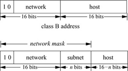
Figure 13.4 Internet interface address structure (in_ifaddr).

As the number of Internet networks has grown, it has become necessary to generalize the handling of Internet addresses to avoid exhausting the set of available network numbers. The new scheme is based on Classless Inter-Domain Routing (CIDR) [Fuller et al, 1993]. The allocation of network addresses does not necessarily follow the boundaries according to class (A, B or C). Instead, an organization may be assigned a contiguous group of addresses described by a single value and mask, such as a group of 16 class C networks (using a 20-bit mask), or one-half of a class C network (using a 25-bit mask). This group of addresses may in turn be subnetted within the organization. In addition, these blocks of addresses are often assigned from a larger block by an Internet service provider, allowing aggregation of routes to clients of the provider. In general, 4.4BSD handles classless addressing in the same fashion as subnets, setting the local network mask along with each address. The local network mask can be set to a value either longer or shorter than that of the mask associated with the network class (A, B, or C). When such a network is subnetted, it would sometimes be desirable to set both the network and subnet masks, although the network mask has little remaining significance. As network routes now include explicit masks (see Section 12.5), the system can route to subnets, traditional network classes, and clusters of networks using the same mechanism.
Broadcast Addresses
On networks capable of supporting broadcast datagrams, 4.2BSD used the address with a host part of zero for broadcasts. After 4.2BSD was released, the Internet broadcast address was defined as the address with a host part of all 1s [Mogul, 1984]. This change and the introduction of subnets both complicated the recognition of broadcast addresses. Hosts may use a host part of 0 or 1s to signify broadcast, and some may understand the presence of subnets, whereas others may not. For these reasons, 4.3BSD and later systems set the broadcast address for each interface to be the host value of all 1s, but allow the alternate address to be set for backward compatibility. If the network is subnetted, the subnet field of the broadcast address contains the normal subnet number. The logical broadcast address for the network also is calculated when the address is set; this address would be the standard broadcast address if subnets were not in use. This address is needed by the IP input routine to filter input packets. On input, 4.4BSD recognizes and accepts subnet and network broadcast addresses with host parts of 0s or 1s, as well as the address with 32 bits of 1 (“broadcast on this physical network”).
Internet Multicast
Many link-layer networks, such as the Ethernet, provide a multicast capability that can address groups of hosts, but is more selective than broadcast because it provides a number of different multicast group addresses. IP provides a similar facility at the network-protocol level, using link-layer multicast where available [Deering, 1989]. IP multicasts are sent using class D destination addresses with high-order bits 1110. Unlike host addresses in classes A, B, and C, class D addresses do not contain network and host portions; instead, the entire address names a group, such as a group of hosts using a particular service. These groups can be created dynamically, and the members of the group can change over time. IP multicast addresses map directly to physical multicast addresses on networks such as the Ethernet, using the low 24 bits of the IP address along with a constant 24-bit prefix to form a 48-bit link-layer address.
For a socket to use multicast, it must join a multicast group using the setsockopt system call. This call informs the link layer that it should receive multicasts for the corresponding link-layer address, and also sends a multicast membership report using the Internet Group Management Protocol (IGMP). Multicast agents on the network can thus keep track of the members of each group. Multicast agents receive all multicast packets from directly attached networks and forward multicast datagrams as needed to group members on other networks. This function is similar to the role of routers that forward normal (unicast) packets, but the criteria for packet forwarding are different, and a packet can be forwarded to multiple neighboring networks.
Internet Ports and Associations
At the IP level, packets are addressed to a host, rather than to a process or communications port. However, each packet contains an 8-bit protocol number that identifies the next protocol that should receive the packet. Internet transport protocols use an additional identifier to designate the connection or communications port on the host. Most protocols (including TCP and UDP) use a 16-bit port number for this purpose. Each protocol maintains its own mapping of port numbers to processes or descriptors. Thus, an association, such as a connection, is fully specified by the tuple <source address, destination address, protocol number, source port, destination port>. Connection-oriented protocols, such as TCP, must enforce the uniqueness of associations; other protocols generally do so as well. When the local part of the address is set before the remote part, it is necessary to choose a unique port number to prevent collisions when the remote part is specified.
Protocol Control Blocks
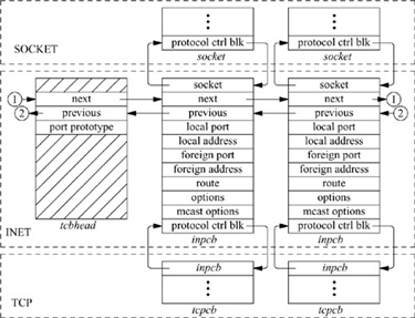
For each TCP- or UDP-based socket, an Internet protocol control block (an inpcb structure) is created to hold Internet network addresses, port numbers, routing information, and pointers to any auxiliary data structures. TCP, in addition, creates a TCP control block (a tcpcb structure) to hold the wealth of protocol state information necessary for its implementation. Internet control blocks for use with TCP are maintained on a doubly linked list private to the TCP protocol module. Internet control blocks for use with UDP are kept on a similar list private to the UDP protocol module. Tw o separate lists are needed because each protocol in the Internet domain has a distinct space of port identifiers. Common routines are used by the individual protocols to add new control blocks to a list, to fix the local and remote parts of an association, to locate a control block by association, and to delete control blocks. IP demultiplexes message traffic based on the protocol identifier specified in its protocol header, and each higher-level protocol is then responsible for checking its list of Internet control blocks to direct a message to the appropriate socket. Figure 13.5 shows the linkage between the socket data structure and these protocol-specific data structures.
Figure 13.5 Internet Protocol data structures.
The implementation of the Internet protocols is rather tightly coupled, as befits the strong intertwining of the protocols. For example, the transport protocols send and receive packets including not only their own header, but also an IP pseudoheader containing the source and destination address, the protocol identifier, and a packet length. This pseudoheader is included in the transport-level packet checksum.
We are now ready to examine the operation of the Internet protocols. We begin with UDP, as it is far simpler than TCP.
13.2 User Datagram Protocol (UDP)
The User Datagram Protocol (UDP) [Postel, 1980] is a simple unreliable datagram protocol that provides only peer-to-peer addressing and optional data checksums.† Its protocol headers are extremely simple, containing only the source and destination port numbers, the datagram length, and the data checksum. The host addresses for a datagram are provided by the IP pseudoheader.
†In 4.4BSD, checksums are enabled or disabled on a system-wide basis and cannot be enabled or disabled on individual sockets.
Initialization
When a new datagram socket is created in the Internet domain, the socket layer locates the protocol-switch entry for UDP and calls the udp_usrreq() routine PRU_ATTACH entry with the socket as a parameter. UDP uses in_pcballoc() to create a new protocol control block on its list of current sockets. It also sets the default limits for the socket send and receive buffers. Although datagrams are never placed in the send buffer, the limit is set as an upper limit on datagram size; the UDP protocol-switch entry contains the flag PR_ATOMIC, requiring that all data in a send operation be presented to the protocol at one time.
If the application program wishes to bind a port number—for example, the well-known port for some datagram service—it calls the bind system call. This request reaches UDP as the PRU_BIND request to udp_usrreq(). The binding may also specify a specific host address, which must be an address of an interface on this host. Otherwise, the address will be left unspecified, matching any local address on input, and with an address chosen as appropriate on each output operation. The binding is done by in_pcbbind(), which verifies that the chosen port number (or address and port) is not in use, then records the local part of the association.
To send datagrams, the system must know the remote part of an association. A program can specify this address and port with each send operation using sendto or sendmsg, or can do the specification ahead of time with the connect system call. In either case, UDP uses the in_pcbconnect() function to record the destination address and port. If the local address was not bound, and if a route for the destination is found, the address of the outgoing interface is used as the local address. If no local port number was bound, one is chosen at this time.
Output
A system call that sends data reaches UDP as a call to udp_usrreq() with the PRU_SEND request and a chain of mbufs containing the data for the datagram. If the call provided a destination address, the address is passed as well; otherwise, the address from a prior connect call is used. The actual output operation is done by udp_output(),
            error = udp_output(inp, m, addr, control);
                struct inpcb *inp;
                struct mbuf *m;
                struct mbuf *addr;
                struct mbuf *control;
where inp is an Internet protocol control block, m is an mbuf chain that contains the data to be sent, and addr is an optional mbuf containing the destination address. Any ancillary data in control are discarded. The destination address could have been prespecified with a connect call; otherwise, it must be provided in the send call. UDP simply prepends its own header, fills in the UDP header fields and those of a prototype IP header, and calculates a checksum before passing the packet on to the IP module for output:
         error = ip_output(m, opt, ro, flags, imo);
             struct mbuf *m, *opt;
             struct route *ro;
             int flags;
             struct ip_moptions *imo;
The call to IP’s output routine is more complicated than is that to UDP’s because the IP routine cannot depend on having a protocol control block that contains information about the current sender and destination. The m parameter indicates the data to be sent, and the opt parameter may specify a list of IP options that should be placed in the IP packet header. For multicast destinations, the imo parameter may reference multicast options, such as the choice of interface and hop count for multicast packets. IP options may be set for a socket with the setsockopt system call specifying the IP protocol level and option IP_OPTIONS. These options are stored in a separate mbuf, and a pointer to this mbuf is stored in the protocol control block for a socket; the pointer is passed to ip_output() with each packet sent. The ro parameter is optional; UDP passes a pointer to the route structure in the protocol control block for the socket. IP will determine a route and leave it in the control block, so that it can be reused on later calls. The flags parameter indicates whether the user is allowed to transmit a broadcast message, and whether routing is to be bypassed for the message being sent (see Section 13.3). The broadcast flag may be inconsequential if the underlying hardware does not support broadcast transmissions. The flags also indicate whether the packet includes an IP pseudoheader or a completely initialized IP header, as when IP forwards packets.
Input
All Internet transport protocols that are layered directly on top of IP use the following calling convention when receiving input packets from IP:
        (void) (*pr_input)(m, hlen);
            struct mbuf *m;
            int hlen;
Each mbuf chain passed is a single packet to be processed by the protocol module. The packet includes the IP header in lieu of a pseudoheader, and the IP header length is passed as the second parameter. The UDP input routine udp_input() is typical of protocol input routines. It first verifies that the length of the packet is at least as long as the IP plus UDP headers, and it uses m_pullup() to make the header contiguous. It then checks that the packet is the correct length and checksums the data if a checksum is present. If any of these tests fail, the packet is simply discarded. Finally, the protocol control block for the socket that is to receive the data is located by in_pcblookup() from the addresses and port numbers in the packet. There might be multiple control blocks with the same local port number, but different local or remote addresses; if so, the control block with the best match is selected. An exact association matches best; but if none exists, a socket with the correct local port number but unspecified local address, remote port number, or remote address will match. A control block with unspecified local or remote addresses thus acts as a wildcard that receives packets for its port if no exact match is found. If a control block is located, the data and the address from which the packet was received are placed in the receive buffer of the indicated socket with sbappendaddr(). If the destination address is a multicast address, copies of the packet are delivered to each socket with matching addresses. Otherwise, if no receiver is found and if the packet was not addressed to a broadcast or multicast address, an ICMP port unreachable error message is sent to the originator of the datagram.†
†This error message normally has no effect, as the sender typically connects to this destination only temporarily, and destroys the association before new input is processed. However, if the sender still has a fully specified association, it may receive notification of the error. The host-name lookup routine in 4.4BSD uses this mechanism to detect the absence of a nameserver at boot time, allowing the lookup routine to fall back to the local host file.
Control Operations
UDP supports few control operations. It supports no options in 4.4BSD, and passes calls to its pr_ctloutput () entry directly to IP. It has a simple pr_ctlinput () routine that receives notification of any asynchronous errors. Some errors simply cause cached routes to be flushed. Other errors are passed to any datagram socket with the indicated destination; only sockets with a destination fixed by a connect call may be notified of errors asynchronously. Such errors are simply noted in the appropriate socket, and socket wakeups are issued in case the process is selecting or sleeping while waiting for input.
When a UDP datagram socket is closed, the udp_usrreq() is called with the PRU_DETACH request. The protocol control block and its contents are simply deleted with in_pcbdetach(); no other processing is required.
13.3 Internet Protocol (IP)
Having examined the operation of a simple transport protocol, we continue with a discussion of the network-layer protocol [Postel, 1981a; Postel et al, 1981]. The Internet Protocol (IP) is the level responsible for host-to-host addressing and routing, packet forwarding, and packet fragmentation and reassembly. Unlike the transport protocols, it does not always operate on behalf of a socket on the local host; it may forward packets, receive packets for which there is no local socket, or generate error packets in response to these situations.
The functions done by IP are illustrated by the contents of its packet header, shown in Fig. 13.6. The header identifies source and destination hosts and the destination protocol, and contains header and packet lengths. The identification and fragment fields are used when a packet or fragment must be broken into smaller sections for transmission on its next hop, and to reassemble the fragments when they arrive at the destination. The fragmentation flags are Don’t Fragment and More Fragments; the latter flag plus the offset are sufficient to assemble the fragments of the original packet at the destination.
Figure 13.6 Internet Protocol header. IHL is the Internet header length specified in units of four octets. Options are delimited by IHL.
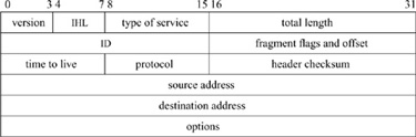
IP options are present in an IP packet if the header length field has a value larger than the minimum. The no-operation option and the end-of-option-list option are each one octet in length. All other options are self-encoding, with a type and length preceding any additional data. Hosts and routers are thus able to skip over options that they do not implement. Examples of existing options are the timestamp and record-route options, which are updated by each router that forwards a packet, and the source-route options, which supply a complete or partial route to the destination.
Output
We have already seen the calling convention for the IP output routine, which is
          error = ip_output(m, opt, ro, flags, imo);
              struct mbuf *m, *opt;
              struct route *ro;
              int flags;
              struct ip_moptions *imo;
As described in the subsection on output in the previous section, the parameter m is an mbuf chain containing the packet to be sent, including a skeletal IP header; opt is an optional mbuf containing IP options to be inserted after the header. If the route ro is given, it may contain a reference to a routing entry (rtentry structure), which specifies a route to the destination from a previous call, and in which any new route will be left for future use. The flags may allow the use of broadcast or may indicate that the routing tables should be bypassed. If present, imo includes options for multicast transmissions.
The outline of the work done by ip_output() is as follows:
• Insert any IP options.
• Fill in the remaining header fields (IP version, zero offset, header length, and a new packet identification) if the packet contains an IP pseudoheader.
• Determine the route (i.e., outgoing interface and next-hop destination).
• Check whether the destination is a multicast address. If it is, determine the outgoing interface and hop count.
• Check whether the destination is a broadcast address; if it is, check whether broadcast is permitted.
• If the packet size is no larger than the maximum packet size for the outgoing interface, compute the checksum and call the interface output routine.
• If the packet size is larger than the maximum packet size for the outgoing interface, break the packet into fragments and send each in turn.
We shall examine the routing step in more detail. First, if no route reference is passed as a parameter, an internal routing reference structure is used temporarily. A route structure that is passed from the caller is checked to see that it is a route to the same destination, and that it is still valid. If either test fails, the old route is freed. After these checks, if there is no route, rtalloc() is called to allocate a route. The route returned includes a pointer to the outgoing interface information. This information includes the maximum packet size, flags including broadcast and multicast capability, and the output routine. If the route is marked with the RTF_GATEWAY flag, the address of the next-hop gateway (router) is given by the route; otherwise, the packet’s destination is the next-hop destination. If routing is to be bypassed because of a MSG_DONTROUTE option (see Section 11.1) or a SO_DONTROUTE option, a directly attached network shared with the destination is found; if there is no directly attached network, an error is returned. Once the outgoing interface and next-hop destination are found, enough information is available to send the packet.
As described in Chapter 12, the interface output routine normally validates the destination address and places the packet on its output queue, returning errors only if the interface is down, the output queue is full, or the destination address is not understood.
Input
In Chapter 12, we described the reception of a packet by a network interface, and the packet’s placement on the input queue for the appropriate protocol. The network-interface handler then schedules the protocol to run by setting a corresponding bit in the network status word and scheduling a software interrupt. The IP input routine is invoked via this software interrupt when network interfaces receive messages for an Internet protocol; consequently, it is called without any parameters. The input routine, ipintr(), removes packets from its input queue one at a time and processes them to completion. A packet’s processing is completed in one of four ways: it is passed as input to a higher-level protocol, it encounters an error that is reported back to the source, it is dropped because of an error, or it is forwarded along the path to its destination. In outline form, the steps in the processing of an IP packet on input are as follows:
1. Verify that the packet is at least as long as an IP header, and ensure that the header is contiguous.
2. Checksum the header of the packet, and discard the packet if there is an error.
3. Verify that the packet is at least as long as the header indicates, and drop the packet if it is not. Trim any padding from the end of the packet.
4. Process any IP options in the header.
5. Check whether the packet is for this host. If it is, continue processing the packet. If it is not, and if doing IP packet forwarding, try to forward the packet. Otherwise, drop the packet.
6. If the packet has been fragmented, keep it until all its fragments are received and reassembled, or until it is too old to keep.
7. Pass the packet to the input routine of the next-higher-level protocol.
When the incoming packet is removed from the input queue, it is accompanied by an indication of the interface on which the packet was received. This information is passed to the next protocol, to the forwarding function, or to the error-reporting function. If any error is detected and is reported to the packet’s originator, the source address of the error message will be set according to the packet’s destination and the incoming interface.
The decision whether to accept a received packet for local processing by a higher-level protocol is not as simple as we might think. If a host has multiple addresses, the packet is accepted if its destination matches one of those addresses. If any of the attached networks support broadcast and the destination is a broadcast address, the packet is also accepted. (For reasons that are given in Section 13.1, there may be as many as five possible broadcast addresses for a given network.)
The IP input routine uses a simple and efficient scheme for locating the input routine for the receiving protocol of an incoming packet. The protocol field in the IP packet is 8 bits long; thus, there are 256 possible protocols. Fewer than 256 protocols are defined or implemented, and the Internet protocol switch has far fewer than 256 entries. Therefore, IP input uses a 256-element mapping array to map from the protocol number to the protocol-switch entry of the receiving protocol. Each entry in the array is initially set to the index of a raw IP entry in the protocol switch. Then, for each protocol with a separate implementation in the system, the corresponding map entry is set to the index of the protocol in the IP protocol switch. When a packet is received, IP simply uses the protocol field to index into the mapping array, and uses the value at that location as the index into the protocol-switch table for the receiving protocol.
Forwarding
Implementations of IP traditionally have been designed for use by either hosts or routers, rather than by both. That is, a system was either an endpoint for IP packets (as source or destination) or a router (which forwards packets between hosts on different networks, but only uses upper-level protocols for maintenance functions). Traditional host systems do not incorporate packet-forwarding functions; instead, if they receive packets not addressed to them, they simply drop the packets. 4.2BSD was the first common IP implementation that attempted to provide both host and router services in normal operation. This approach had advantages and disadvantages. It meant that 4.2BSD hosts connected to multiple networks could serve as routers as well as hosts, reducing the requirement for dedicated router machines. Early routers were neither inexpensive nor especially powerful. On the other hand, the existence of router-function support in ordinary hosts made it more likely for misconfiguration errors to result in problems on the attached networks. The most serious problem had to do with forwarding of a broadcast packet because of a misunderstanding by either the sender or the receiver of the packet’s destination. The packet-forwarding router functions are disabled by default in 4.4BSD. They may be enabled when a kernel binary is configured, and can be enabled at run time with the sysctl call. Hosts not configured as routers never attempt to forward packets or to return error messages in response to misdirected packets. As a result, far fewer misconfiguration problems are capable of causing synchronized or repetitive broadcasts on a local network, called broadcast storms.
The procedure for forwarding IP packets received at a router but destined for another host is the following:
1. Check that forwarding is enabled. If it is not, drop the packet.
2. Check that the destination address is one that allows forwarding. Packets destined for network 0, network 127 (the official loopback network), or illegal network addresses cannot be forwarded.
3. Save at most 64 octets of the received message, in case an error message must be generated in response.
4. Determine the route to be used in forwarding the packet.
5. If the outgoing route uses the same interface as that on which the packet was received, and if the originating host is on that network, send an ICMP redirect message to the originating host. (ICMP is described in Section 13.8.)
6. Call ip_output() to send the packet to its destination or to the next-hop gateway.
7. If an error is detected, send an ICMP error message to the source host.
Multicast transmissions are handled separately from other packets. Systems may be configured as multicast agents independently from other routing functions. Multicast agents receive all incoming multicast packets, and forward those packets to local receivers and group members on other networks according to group memberships and the remaining hop count of incoming packets.
13.4 Transmission Control Protocol (TCP)
The major protocol of the Internet protocol suite is the Transmission Control Protocol (TCP) [Postel, 1981b; Cerf & Kahn, 1974]. TCP is the reliable connection-oriented stream transport protocol on which most application protocols are based. It includes several features not found in the other transport and network protocols described so far:
• Explicit and acknowledged connection initiation and termination
• Reliable, in-order, unduplicated delivery of data
• Flow control
• Out-of-band indication of urgent data
• Congestion avoidance
Because of these features, the TCP implementation is much more complicated than are those of UDP and IP. These complications, along with the prevalence of the use of TCP, make the details of TCP’s implementation both more critical and more interesting than are the implementations of the simpler protocols. We shall begin with an examination of the TCP itself, then continue with a description of its implementation in 4.4BSD.
A TCP connection may be viewed as a bidirectional, sequenced stream of data octets transferred between two peers. The data may be sent in packets of varying sizes and at varying intervals—for example, when they are used to support a login session over the network. The stream initiation and termination are explicit events at the start and end of the stream, and they occupy positions in the sequence space of the stream so that they can be acknowledged in the same manner as data are. Sequence numbers are 32-bit numbers from a circular space; that is, comparisons are made modulo 232, so that zero is the next sequence number after 232–1. The sequence numbers for each direction start with an arbitrary value, called the initial sequence number, sent in the initial packet for a connection. In accordance with the TCP specification, the TCP implementation selects the initial sequence number by sampling a software counter that increments at about 250 KHz, then incrementing the counter so that later connections choose a different starting point, reducing the chance that an old duplicate packet will match the sequence space of a current connection. 4.4BSD includes a random component in the counter value so that the initial sequence number is somewhat less predictable, making it harder to “spoof” a network connection. Each packet of a TCP connection carries the sequence number of its first datum and (except during connection establishment) an acknowledgment of all contiguous data received. A TCP packet is known as a segment because it begins at a specific location in the sequence space and has a specific length. Acknowledgments are specified as the sequence number of the next sequence number not yet received. Acknowledgments are cumulative, and thus may acknowledge data received in more than one (or part of one) packet. A packet may or may not contain data, but always contains the sequence number of the next datum to be sent.
Flow control in TCP is done with a sliding-window scheme. Each packet with an acknowledgment contains a window, which is the number of octets of data that the receiver is prepared to accept, beginning with the sequence number in the acknowledgment. The window is a 16-bit field, limiting the window to 65535 octets by default; however, the use of a larger window may be negotiated (see the next subsection). Urgent data are handled similarly; if the flag indicating urgent data is set, the urgent-data pointer is used as a positive offset from the sequence number of the packet to indicate the extent of urgent data. Thus, TCP can send notification of urgent data without sending all intervening data, even if the flow-control window would not allow the intervening data to be sent.
The complete header for a TCP packet is shown in Fig. 13.7. The flags include SYN and FIN, denoting the initiation (synchronization) and completion of a connection. Each of these flags occupies a sequence space of one. A complete connection thus consists of a SYN, zero or more octets of data, and a FIN sent from each peer and acknowledged by the other peer. Additional flags indicate whether the acknowledgment field (ACK) and urgent fields (URG) are valid, and include a connection-abort signal (RST). The header includes a header-length field so that the header can be extended with optional fields. Options are encoded in the same way as are IP options: the no-operation and end-of-options options are single octets, and all other options include a type and a length. The only option in the initial specification of TCP indicates the maximum segment (packet) size that a correspondent is willing to accept; this option is used only during initial connection establishment. Several other options have been defined. To avoid confusion, the protocol standard allows these options to be used in data packets only if both endpoints include them during establishment of the connection.
Figure 13.7 TCP packet header.

TCP Connection States
The connection-establishment and connection-completion mechanisms of TCP are designed for robustness. They serve to frame the data that are transferred during a connection, so that not only the data but also their extent are communicated reliably. In addition, the procedure is designed to discover old connections that have not terminated correctly because of a crash of one peer or loss of network connectivity. If such a half-open connection is discovered, it is aborted. Hosts choose new initial sequence numbers for each connection to lessen the chances that an old packet may be confused with a current connection.
The normal connection-establishment procedure is known as a three-way handshake. Each peer sends a SYN to the other, and each in turn acknowledges the other’s SYN with an ACK. In practice, a connection is normally initiated by one of the two (the client) attempting to connect to the other (a server listening on a well-known port). The client chooses a port number and initial sequence number and uses these selections in the initial packet with a SYN. The server creates a new connection block for the pending connection and sends a packet with its initial sequence number, a SYN, and an ACK of the client’s SYN. The client responds with an ACK of the server’s SYN, completing connection establishment. As the ACK of the first SYN is piggybacked on the second SYN, this procedure requires three packets, leading to the term three-way handshake. (The protocol still operates correctly if both peers initiate the connection simultaneously, although it requires four packets in that case.)
4.4BSD includes three options along with SYN when initiating a connection. One contains the maximum segment size that the system is willing to accept. The other two options are more recent additions [Jacobson et al, 1992]. The first of these options specifies a window-scaling value expressed as a binary shift value, allowing the window to exceed 65535 octets. If both peers include this option during the three-way handshake, both scaling values take effect; otherwise, the window value remains in octets. The third option is a timestamp option. If this option is sent in both directions during connection establishment, it will also be sent in each packet during data transfer. The data field of the timestamp option includes a timestamp associated with the current sequence number, and also echoes a timestamp associated with the current acknowledgment. Like the sequence space, the timestamp uses a 32-bit field and modular arithmetic. The unit of the timestamp field is not defined, although it must fall between 1 millisecond and 1 second. The value sent by each system must be monotonically nondecreasing during a connection. 4.4BSD uses the value of a counter that is incremented twice per second. These timestamps can be used to implement round-trip timing. They also serve as an extension of the sequence space to prevent old duplicate packets from being accepted; this extension is valuable when a large window or a fast path is used.
After a connection is established, each peer includes an acknowledgment and window information in each packet. Each may send data according to the window that it receives from its peer. As data are sent by one end, the window becomes filled. As data are received by the peer, acknowledgments may be sent so that the sender can discard the data from its send queue. If the receiver is prepared to accept additional data, perhaps because the receiving process has consumed the previous data, it will also advance the flow-control window. Data, acknowledgments, and window updates may all be combined in a single message.
Table 13.1 TCP connection states.

If a sender does not receive an acknowledgment within some reasonable time, it retransmits data that it presumes were lost. Duplicate data are discarded by the receiver but are acknowledged again in case the retransmission was caused by loss of the acknowledgment. If the data are received out of order, the receiver generally retains the out-of-order data for use when the missing segment is received. Out-of-order data cannot be acknowledged, because acknowledgments are cumulative.†
†A selective acknowledgment mechanism was introduced in [Jacobson et al, 1992], but is not implemented in 4.4BSD.
Each peer may terminate data transmission at any time by sending a packet with the FIN bit. A FIN represents the end of the data (like an end-of-file indication). The FIN is acknowledged, advancing the sequence number by 1. The connection may continue to carry data in the other direction until a FIN is sent in that direction. The acknowledgment of that FIN terminates the connection. To guarantee synchronization at the conclusion of the connection, the peer sending the last ACK of a FIN must retain state long enough that any retransmitted FIN packets would have reached it or have been discarded; otherwise, if the ACK were lost and a retransmitted FIN were received, the receiver would be unable to repeat the acknowledgment. This interval is arbitrarily set to twice the maximum expected segment lifetime (known as 2MSL).
The TCP input-processing module and timer modules must maintain the state of a connection throughout that connection’s lifetime. Thus, in addition to processing data received on the connection, the input module must process SYN and FIN flags and other state transitions. The list of states for one end of a TCP connection is given in Table 13.1. Figure 13.8 shows the finite-state machine made up by these states, the events that cause transitions, and the actions during the transitions. An earlier version of the TCP implementation was implemented as an explicit state machine.
If a connection is lost because of a crash or timeout on one peer, but is still considered established by the other, then any data sent on the connection and received at the other end will cause the half-open connection to be discovered. When a half-open connection is detected, the receiving peer sends a packet with the RST flag and a sequence number derived from the incoming packet to signify that the connection is no longer in existence.

Figure 13.8 TCP state diagram. TCB—TCP control block; 2MSL—twice maximum segment lifetime.
Sequence Variables
Each TCP connection maintains a large set of state variables in the TCP control block. This information includes the connection state, timers, options and state flags, a queue that holds data received out of order, and several sequence number variables. The sequence variables are used to define the send and receive sequence space, including the current window for each. The window is the range of data sequence numbers that are currently allowed to be sent, from the first octet of data not yet acknowledged up to the end of the range that has been offered in the window field of a header. The variables used to define the windows in 4.4BSD are a superset of those used in the protocol specification [Postel, 1981b]. The send and receive windows are shown in Fig. 13.9. The meanings of the sequence variables are listed in Table 13.2.
The area between snd_una and snd_una + snd_wnd is known as the send window. Data for the range snd_una to snd_max have been sent but not yet acknowledged, and are kept in the socket send buffer along with data not yet transmitted. The snd_nxt field indicates the next sequence number to be sent, and is incremented as data are transmitted. The area from snd_nxt to snd_una + snd_wnd is the remaining usable portion of the window, and its size determines whether additional data may be sent. The snd_nxt and snd_max values are normally maintained together except when TCP is retransmitting.
The area between rcv_nxt and rcv_nxt + rcv_wnd is known as the receive window. These variables are used in the output module to decide whether data can be sent, and in the input module to decide whether data that are received can be accepted. When the receiver detects that a packet is not acceptable because the data are all outside the window, it drops the packet, but sends a copy of its most recent acknowledgment. If the packet contained old data, the first acknowledgment may have been lost, and thus it must be repeated. The acknowledgment also includes a window update, synchronizing the sender’s state with the receiver’s state.

Figure 13.9 TCP sequence space.

Table 13.2 TCP sequence variables.
If the TCP timestamp option is in use for the connection, the tests to see whether an incoming packet is acceptable are augmented with checks on the timestamp. Each time that an incoming packet is accepted as the next expected packet, its timestamp is recorded in the ts_recent field in the TCP protocol control block. If an incoming packet includes a timestamp, the timestamp is compared to the most recently received timestamp. If the timestamp is less than the previous value, the packet is discarded as being an old duplicate and a current acknowledgment is sent in response. In this way, the timestamp serves as an extension to the sequence number, avoiding accidental acceptance of an old duplicate when the window is large or sequence numbers can be reused quickly. However, because of the granularity of the timestamp value, a timestamp received more than 24 days ago cannot be compared to a new value, and this test is bypassed. The current time is recorded when ts_recent is updated from an incoming timestamp to make this test. Of course, connections are seldom idle for longer than 24 days.
13.5 TCP Algorithms
Now that we have introduced TCP, its state machine, and its sequence space, we can begin to examine the implementation of the protocol in 4.4BSD. Several aspects of the protocol implementation depend on the overall state of a connection. The TCP connection state, output state, and state changes depend on external events and timers. TCP processing occurs in response to one of three events:
1. A request from the user, such as sending data, removing data from the socket receive buffer, or opening or closing a connection
2. The receipt of a packet for the connection
3. The expiration of a timer
These events are handled in the routines tcp_usrreq(), tcp_input(), and tcp_timers(), respectively. Each routine processes the current event and makes any required changes in the connection state. Then, for any transition that may require output, the tcp_output() routine is called to do any output that is necessary.
The criteria for sending a packet with data or control information are complicated, and therefore the TCP send policy is the most interesting and important part of the protocol implementation. For example, depending on the state- and flow-control parameters for a connection, any of the following may allow to be sent data that could not be sent previously:
• A user send call that places new data in the send queue
• The receipt of a window update from the peer TCP
• The expiration of the retransmission timer
• The expiration of the window-update (persist) timer
In addition, the tcp_output() routine may decide to send a packet with control information, even if no data may be sent, for any of these reasons:
• A change in connection state (e.g., open request, close request)
• Receipt of data that must be acknowledged
• A change in the receive window because of removal of data from the receive queue
• A send request with urgent data
• A connection abort
We shall consider most of these decisions in greater detail after we have described the states and timers involved. We begin with algorithms used for timing, connection setup, and shutdown; they are distributed through several parts of the code. We continue with the processing of new input and an overview of output processing and algorithms.
Timers
Unlike a UDP socket, a TCP connection maintains a significant amount of state information, and, because of that state, some operations must be done asynchronously. For example, data might not be sent immediately when a process presents them, because of flow control. The requirement for reliable delivery implies that data must be retained after they are first transmitted so that they can be retransmitted if necessary. To prevent the protocol from hanging if packets are lost, each connection maintains a set of timers used to recover from losses or failures of the peer TCP. These timers are stored in the protocol control block for a connection. Whenever they are set, they are decremented every 500 milliseconds by the tcp_slowtimo() routine (called as the TCP protocol switch pr_slowtimo routine) until they expire, triggering a call to tcp_timers().
Two timers are used for output processing. One is the retransmit timer (TCPT_REXMT). Whenever data are sent on a connection, the retransmit timer is started, unless it is already running. When all outstanding data are acknowledged, the timer is stopped. If the timer expires, the oldest unacknowledged data are resent (at most one full-sized packet) and the timer is restarted with a longer value. The rate at which the timer value is increased (the timer backoff) is determined by a table of multipliers that provides an exponential increase in timeout values up to a ceiling.
The other timer used for maintaining output flow is the persist timer (TCPT_PERSIST). This timer protects against the other type of packet loss that could cause a connection to constipate: the loss of a window update that would allow more data to be sent. Whenever data are ready to be sent, but the send window is too small to bother sending (zero, or less than a reasonable amount), and no data are already outstanding (the retransmit timer is not set), the persist timer is started. If no window update is received before the timer expires, the output routine sends as large a segment as the window allows. If that size is zero, it sends a window probe (a single octet of data) and restarts the persist timer. If a window update was lost in the network, or if the receiver neglected to send a window update, the acknowledgment will contain current window information. On the other hand, if the receiver is still unable to accept additional data, it should send an acknowledgment for previous data with a still-closed window. The closed window might persist indefinitely; for example, the receiver might be a network-login client, and the user might stop terminal output and leave for lunch (or vacation).
The third timer used by TCP is a keepalive timer (TCPT_KEEP). The keepalive timer has two different purposes at different phases of a connection. During connection establishment, this timer limits the time for the three-way handshake to complete. If it expires, the connection is timed out. Once the connection completes, the keepalive timer monitors idle connections that might no longer exist on the correspondent TCP because of timeout or a crash. If a socket-level option is set and the connection has been idle since the most recent keepalive timeout, the timer routine will send a keepalive packet designed to produce either an acknowledgment or a reset (RST) from the peer TCP. If a reset is received, the connection will be closed; if no response is received after several attempts, the connection will be dropped. This facility is designed so that network servers can avoid languishing forever if the client disappears without closing. Keepalive packets are not an explicit feature of the TCP protocol. The packets used for this purpose by 4.4BSD set the sequence number to 1 less than snd_una, which should elicit an acknowledgment from the correspondent TCP if the connection still exists.†
†In 4.4 BSD, the keepalive packet contains no data unless the system is configured with a kernel option for compatibility with 4.2BSD, in which case a single null octet is sent. A bug prevented 4.2BSD from responding to a keepalive packet unless the packet contained data. This option should no longer be necessary.
The final TCP timer is known as the 2MSL timer (TCPT_2MSL; “twice the maximum segment lifetime”). TCP starts this timer when a connection is completed by sending an acknowledgment for a FIN (from FIN_WAIT_2) or by receiving an ACK for a FIN (from CLOSING state, where the send side is already closed). Under these circumstances, the sender does not know whether the acknowledgment was received. If the FIN is retransmitted, it is desirable that enough state remain that the acknowledgment can be repeated. Therefore, when a TCP connection enters the TIME_WAIT state, the 2MSL timer is started; when the timer expires, the control block is deleted. If a retransmitted FIN is received, another ACK is sent and the timer is restarted. To prevent this delay from blocking a process closing the connection, any process close request is returned successfully without the process waiting for the timer. Thus, a protocol control block may continue its existence even after the socket descriptor has been closed. In addition, 4.4BSD starts the 2MSL timer when FIN_WAIT_2 state is entered after the user has closed; if the connection is idle until the timer expires, it will be closed. Because the user has already closed, new data cannot be accepted on such a connection in any case. This timer is set because certain other TCP implementations (incorrectly) fail to send a FIN on a receive-only connection. Connections to such hosts would remain in FIN_WAIT_2 state forever if the system did not have a timeout.
In addition to the four timers implemented by the TCP tcp_slowtimo() routine, TCP uses the protocol switch pr_fasttimo entry. The tcp_fasttimo() routine, called every 200 milliseconds, processes delayed acknowledgment requests. These functions will be described in Section 13.6.
Estimation of Round-Trip Time
When connections must traverse slow networks that lose packets, an important decision determining connection throughput is the value to be used when the retransmission timer is set. If this value is too large, data flow will stop on the connection for an unnecessarily long time before the dropped packet is resent. Another round-trip time interval is required for the sender to receive an acknowledgment of the resent segment and a window update, allowing it to send new data. (With luck, only one segment will have been lost, and the acknowledgment will include the other segments that had been sent.) If the timeout value is too small, however, packets will be retransmitted needlessly. If the cause of the network slowness or packet loss is congestion, then unnecessary retransmission only exacerbates the problem. The traditional solution to this problem in TCP is for the sender to estimate the round-trip time (rtt) for the connection path by measuring the time required to receive acknowledgments for individual segments. The system maintains an estimate of the round-trip time as a smoothed moving average, srtt [Postel, 1981b], using
srtt = (ALPHA × srtt) + ((1 - ALPHA) × rtt).
Older versions of the system set the initial retransmission timeout to a constant multiple (BETA) of the current smoothed round-trip time, with a smoothing factor ALPHA of 0.9 (retaining 90 percent of the previous average) and a variance factor BETA of 2. BSD versions, beginning with the 4.3BSD Tahoe release, use a more sophisticated algorithm. In addition to a smoothed estimate of the round-trip time, TCP keeps a smoothed variance (estimated as mean difference, to avoid square-root calculations in the kernel). It employs an ALPHA value of 0.875 for the round-trip time and a corresponding smoothing factor of 0.75 for the variance. These values were chosen in part so that the system could compute the smoothed av erages using shift operations on fixed-point values, instead of using floating-point values, as the earlier system did. (On many hardware architectures, it is expensive to use floating-point arithmetic in interrupt routines, because doing so forces floating-point registers and status to be saved and restored.) The initial retransmission timeout is then set to the current smoothed round-trip time plus four times the smoothed variance. This algorithm is substantially more efficient on long-delay paths with little variance in delay, such as satellite links, because it computes the BETA factor dynamically [Jacobson, 1988].
For simplicity, the variables in the TCP protocol control block allow measurement of the round-trip time for only one sequence value at a time. This restriction prevents accurate time estimation when the window is large; only one packet per window can be timed. However, if the TCP timestamps option is supported by both peers, a timestamp is sent with each data packet and is returned with each acknowledgment. In this case, estimates of round-trip time can be obtained with each new acknowledgment; the quality of the smoothed average and variance is thus improved, and the system can respond more quickly to changes in network conditions.
Connection Establishment
There are two ways in which a new TCP connection can be established. An active connection is initiated by a connect call, whereas a passive connection is created when a listening socket receives a connection request. We consider each in turn.
The initial steps of an active connection attempt are similar to the actions taken during the creation of a UDP socket. The process creates a new socket, resulting in a call to tcp_usrreq() with the PRU_ATTACH request. TCP creates an inpcb protocol control block just as does UDP, then creates an additional control block (a tcpcb structure), as described in Section 13.1. Some of the flow-control parameters in the tcpcb are initialized at this time. If the process explicitly binds an address or port number to the connection, the actions are identical to those for a UDP socket. Then, a connect call initiates the actual connection. The first step is to set up the association with in_pcbconnect(), again identically to this step in UDP. A packet-header template is created for use in construction of each output packet. An initial sequence number is chosen from a sequence-number prototype, which is then advanced by a substantial amount. The socket is then marked with soisconnecting(), the TCP connection state is set to TCPS_SYN_SENT, the keepalive timer is set (to 75 seconds) to limit the duration of the connection attempt, and tcp_output() is called for the first time.
The output-processing module tcp_output() uses an array of packet control flags indexed by the connection state to determine which control flags should be sent in each state. In the TCPS_SYN_SENT state, the SYN flag is sent. Because it has a control flag to send, the system sends a packet immediately using the prototype just constructed and including the current flow-control parameters. The packet normally contains three option fields: a maximum-segment-size option, a window-scale option and a timestamps option (see Section 13.4). The maximum-segment-size option communicates the largest segment size that TCP is willing to accept. To compute this value, the system locates a route to the destination. If the route specifies a maximum transmission unit (MTU), the system uses that value after allowing for packet headers. If the connection is to a destination on a local network (or a subnet of a local network—see Section 13.1), the maximum transmission unit of the outgoing network interface is used, possibly rounding down to a multiple of the mbuf cluster size for efficiency of buffering. If the destination is not local and nothing is known about the intervening path,† the default segment size (512 octets) is used. The retransmit timer is set to the default value (6 seconds), because no round-trip time information is available yet.
†TCP should use Path MTU Discovery as described in [Mogul & Deering, 1990]. However, this feature is not implemented in 4.4BSD.
With a bit of luck, a responding packet will be received from the target of the connection before the retransmit timer expires. If not, the packet is retransmitted and the retransmit timer is restarted with a greater value. If no response is received before the keepalive timer expires, the connection attempt is aborted with a “Connection timed out” error. If a response is received, however, it is checked for agreement with the outgoing request. It should acknowledge the SYN that was sent, and should include a SYN. If it does both, the receive sequence variables are initialized, and the connection state is advanced to TCPS_ESTABLISHED. If a maximum-segment-size option is present in the response, the maximum segment size for the connection is set to the minimum of the offered size and the maximum transmission unit of the outgoing interface; if the option is not present, the default size (512 data bytes) is recorded. The flag TF_ACKNOW is set in the TCP control block before the output routine is called, so that the SYN will be acknowledged immediately. The connection is now ready to transfer data.
The events that occur when a connection is created by a passive open are different. A socket is created and its address is bound as before. The socket is then marked by the listen call as willing to accept connections. When a packet arrives for a TCP socket in TCPS_LISTEN state, a new socket is created with sonewconn(), which calls the TCP PRU_ATTACH request to create the protocol control blocks for the new socket. The new socket is placed on the queue of partial connections headed by the listening socket. If the packet contains a SYN and is otherwise acceptable, the association of the new socket is bound, both the send and the receive sequence numbers are initialized, and the connection state is advanced to TCPS_SYN_RECEIVED. The keepalive timer is set as before, and the output routine is called after TF_ACKNOW has been set to force the SYN to be acknowledged; an outgoing SYN is sent as well. If this SYN is acknowledged properly, the new socket is moved from the queue of partial connections to the queue of completed connections. If the owner of the listening socket is sleeping in an accept call or does a select, the socket will indicate that a new connection is available. Again, the socket is finally ready to send data. Up to one window of data may have already been received and acknowledged by the time that the accept call completes.
Connection Shutdown
A TCP connection is symmetrical and full-duplex, so either side may initiate disconnection independently. As long as one direction of the connection can carry data, the connection remains open. A socket may indicate that it has completed sending data with the shutdown system call, which results in a call to the tcp_usrreq() routine with request PRU_SHUTDOWN. The response to this request is that the state of the connection is advanced; from the ESTABLISHED state, the state becomes FIN_WAIT_1. The ensuing output call will send a FIN, indicating an endof-file. The receiving socket will advance to CLOSE_WAIT, but may continue to send. The procedure may be different if the process simply closes the socket; in that case, a FIN is sent immediately, but if new data are received, they cannot be delivered. Normally, higher-level protocols conclude their own transactions such that both sides know when to close. If they do not, however, TCP must refuse new data; it does so by sending a packet with RST set if new data are received after the user has closed. If data remain in the send buffer of the socket when the close is done, TCP will normally attempt to deliver them. If the socket option SO_LINGER was set with a linger time of zero, the send buffer is simply flushed; otherwise, the user process is allowed to continue, and the protocol waits for delivery to conclude. Under these circumstances, the socket is marked with the state bit SS_NOFDREF (no file-descriptor reference). The completion of data transfer and the final close can take place an arbitrary amount of time later. When TCP finally completes the connection (or gives up because of timeout or other failure), it calls tcp_close(). The protocol control blocks and other dynamically allocated structures are freed at this time. The socket also is freed if the SS_NOFDREF flag has been set. Thus, the socket remains in existence as long as either a file descriptor or a protocol control block refers to it.
13.6 TCP Input Processing
Although TCP input processing is considerably more complicated than is UDP input handling, the preceding sections have provided the background that we need to examine the actual operation. As always, the input routine is called with parameters
       (void) tcp_input(m, hlen);
           struct mbuf *m;
           int hlen;
The first few steps probably are beginning to sound familiar:
1. Locate the TCP header in the received IP datagram. Make sure that the packet is at least as long as a TCP header, and use m_pullup() if necessary to make it contiguous.
2. Compute the packet length, set up the IP pseudoheader, and checksum the TCP header and data. Discard the packet if the checksum is bad.
3. Check the TCP header length; if it is larger than a minimal header, make sure that the whole header is contiguous.
4. Locate the protocol control block for the connection with the port number specified. If none exists, send a packet containing the reset flag RST and drop the packet.
5. Check whether the socket is listening for connections; if it is, follow the procedure described for passive connection establishment.
6. Process any TCP options from the packet header.
7. Clear the idle time for the connection, and set the keepalive timer to its normal value.
At this point, the normal checks have been made, and we are prepared to deal with data and control flags in the received packet. There are still many consistency checks that must be made during normal processing; for example, the SYN flag must be present if we are still establishing a connection, and must not be present if the connection has been established. We shall omit most of these checks from our discussion, but the tests are important to prevent wayward packets from causing confusion and possible data corruption.
The next step in checking a TCP packet is to see whether the packet is acceptable according to the receive window. It is important that this step be done before control flags—in particular RST—are examined, because old or extraneous packets should not affect the current connection unless they are clearly relevant in the current context. A segment is acceptable if the receive window has nonzero size, and if at least some of the sequence space occupied by the packet falls within the receive window. If the packet contains data, some of the data must fall within the window; portions of the data that precede the window are trimmed, as they have already been received, and portions that exceed the window also are discarded, as they have been sent prematurely. If the receive window is closed (rcv_wnd is zero), then only segments with no data and with a sequence number equal to rcv_nxt are acceptable. If an incoming segment is not acceptable, it is dropped after an acknowledgment is sent.
The processing of incoming TCP packets must be fully general, taking into account all the possible incoming packets and possible states of receiving endpoints. However, the bulk of the packets processed falls into two general categories. Typical packets contain either the next expected data segment for an existing connection or an acknowledgment plus a window update for one or more data segments, with no additional flags or state indications. Rather than considering each incoming segment based on first principles, tcp_input() checks first for these common cases. This algorithm is known as header prediction. If the incoming segment matches a connection in the ESTABLISHED state, if it contains the ACK flag but no other flags, if the sequence number is the next value expected (and the timestamp, if any, is nondecreasing), if the window field is the same as in the previous segment, and if the connection is not in a retransmission state, then the incoming segment is one of the two common types. The system processes any timestamp option that the segment contains, recording the value received to be included in the next acknowledgment. If the segment contains no data, it is a pure acknowledgment with a window update. In the usual case, round-trip–timing information is sampled if it is available, acknowledged data are dropped from the socket send buffer, and the sequence values are updated. The packet is discarded once the header values have been checked. The retransmit timer is canceled if all pending data have been acknowledged; otherwise, it is restarted. The socket layer is notified if any process might be waiting to do output. Finally, tcp_output() is called because the window has moved forward, and that operation completes the handling of a pure acknowledgment.
If a packet meeting the tests for header prediction contains the next expected data, if no out-of-order data are queued for the connection, and if the socket receive buffer has space for the incoming data, then this packet is a pure in-sequence data segment. The sequencing variables are updated, the packet headers are removed from the packet, and the remaining data are appended to the socket receive buffer. The socket layer is notified so that it can notify any interested process, and the control block is marked with a flag indicating that an acknowledgment is needed. No additional processing is required for a pure data packet.
For packets that are not handled by the header-prediction algorithm, the processing steps are as follows:
1. Process the timestamp option if it is present, rejecting any packets for which the timestamp has decreased, first sending a current acknowledgment.
2. Check whether the packet begins before rcv_nxt. If it does, ignore any SYN in the packet, and trim any data that fall before rcv_nxt. If no data remain, send a current acknowledgment and drop the packet. (The packet is presumed to be a duplicate transmission.)
3. If the packet still contains data after trimming, and the process that created the socket has already closed the socket, send a reset (RST) and drop the connection. This reset is necessary to abort connections that cannot complete; it typically is sent when a remote-login client disconnects while data are being received.
4. If the end of the segment falls after the window, trim any data beyond the window. If the window was closed and the packet sequence number is rcv_nxt, the packet is treated as a window probe; TF_ACKNOW is set to send a current acknowledgment and window update, and the remainder of the packet is processed. If SYN is set and the connection was in TIME_WAIT state, this packet is really a new connection request, and the old connection is dropped; this procedure is called rapid connection reuse. Otherwise, if no data remain, send an acknowledgment and drop the packet.
The remaining steps of TCP input processing check the following flags and fields and take the appropriate actions: RST, ACK, window, URG, data, and FIN. Because the packet has already been confirmed to be acceptable, these actions can be done in a straightforward way:
5. If a timestamp option is present, and the packet includes the next sequence number expected, record the value received to be included in the next acknowledgment.
6. If RST is set, close the connection and drop the packet.
7. If ACK is not set, drop the packet.
8. If the acknowledgment-field value is higher than that of previous acknowledgments, new data have been acknowledged. If the connection was in SYN_RECEIVED state and the packet acknowledges the SYN sent for this connection, enter ESTABLISHED state. If the packet includes a timestamp option, use it to compute a round-trip time sample; otherwise, if the sequence range that was newly acknowledged includes the sequence number for which the round-trip time was being measured, this packet provides a sample. Av erage the time sample into the smoothed round-trip time estimate for the connection. If all outstanding data have been acknowledged, stop the retransmission timer; otherwise, set it back to the current timeout value. Finally, drop from the send queue in the socket the data that were acknowledged. If a FIN has been sent and was acknowledged, advance the state machine.
9. Check the window field to see whether it advances the known send window. First, check whether this packet is a new window update. If the sequence number of the packet is greater than that of the previous window update, or the sequence number is the same but the acknowledgment-field value is higher, or if both sequence and acknowledgment are the same but the window is larger, record the new window.
10. If the urgent-data flag URG is set, compare the urgent pointer in the packet to the last-received urgent pointer. If it is different, new urgent data have been sent. Use the urgent pointer to compute so_oobmark, the offset from the beginning of the socket receive buffer to the urgent mark (Section 11.6), and notify the socket with sohasoutofband(). If the urgent pointer is less than the packet length, the urgent data have all been received. TCP normally removes the final data octet sent in urgent mode (the last octet before the urgent pointer), and places that octet in the protocol control block until it is requested with a PRU_RCVOOB request. (The end of the urgent data is a subject of disagreement; the BSD interpretation follows the original TCP specification.) A socket option, SO_OOBINLINE, may request that urgent data be left in the queue with the normal data, although the mark on the data stream is still maintained.
11. At long last, examine the data field in the received packet. If the data begin with rcv_nxt, then they can be placed directly into the socket receive buffer with sbappend(). The flag TF_DELACK is set in the protocol control block to indicate that an acknowledgment is needed, but the latter is not sent immediately in hope that it can be piggybacked on any packets sent soon (presumably in response to the incoming data) or combined with acknowledgment of other data received soon; see the subsection on delayed acknowledgments and window updates in Section 13.7. If no activity causes a packet to be returned before the next time that the tcp_fasttimo() routine runs, it will change the flag to TF_ACKNOW and call the tcp_output() routine to send the acknowledgment. Acknowledgments can thus be delayed by no more than 200 milliseconds. If the data do not begin with rcv_nxt, the packet is retained in a per-connection queue until the intervening data arrive, and an acknowledgment is sent immediately.
12. As the final step in processing a received packet, check for the FIN flag. If it is present, the connection state machine may have to be advanced, and the socket is marked with socantrcvmore() to convey the end-of-file indication. If the send side has already closed (a FIN was sent and acknowledged), the socket is now considered closed, and it is so marked with soisdisconnected(). The TF_ACKNOW flag is set to force immediate acknowledgment.
Step 10 completes the actions taken when a new packet is received by tcp_input(). However, as noted earlier in this section, receipt of input may require new output. In particular, acknowledgment of all outstanding data or a new window update requires either new output or a state change by the output module. Also, several special conditions set the TF_ACKNOW flag. In these cases, tcp_output() is called at the conclusion of input processing.
13.7 TCP Output Processing
We are finally ready to investigate the most interesting part of the TCP implementation—the send policy. As we saw earlier, a TCP packet contains an acknowledgment and a window field as well as data, and a single packet may be sent if any of these three fields change. A naive TCP send policy might send many more packets than necessary. For example, consider what happens when a user types one character to a remote-terminal connection that uses remote echo. The server-side TCP receives a single-character packet. It might send an immediate acknowledgment of the character. Then, milliseconds later, the login server would read the character, removing the character from the receive buffer; the TCP might immediately send a window update noting that one additional octet of send window was available. After another millisecond or so, the login server would send an echoed character back to the client, necessitating a third packet sent in response to the single character of input. It is obvious that all three responses (the acknowledgment, the window update, and the data return) could be sent in a single packet. However, if the server were not echoing input data, the acknowledgment could not be withheld for too long a time or the client-side TCP would begin to retransmit. The algorithms used in the send policy to minimize network traffic yet to maximize throughput are the most subtle part of a TCP implementation. The send policy used in 4.4BSD includes several standard algorithms, as well as a few approaches suggested by the network research community. We shall examine each part of the send policy.
As we saw in the previous section, there are several different events that may trigger the sending of data on a connection; in addition, packets must be sent to communicate acknowledgments and window updates (consider a one-way connection!).
Sending of Data
The most obvious reason that the tcp output module tcp_output() is called is that the user has written new data to the socket. Write operations are done with a call to tcp_usrreq() with the PRU_SEND request. (Recall that sosend() waits for enough space in the socket send buffer if necessary, then copies the user’s data into a chain of mbufs that is passed to the protocol with the PRU_SEND request.) The action in tcp_usrreq() is simply to place the new output data in the socket’s send buffer with sbappend(), and to call tcp_output(). If flow control permits, tcp_output() will send the data immediately.
The actual send operation is not substantially different from one for a UDP datagram socket. The differences are that the header is more complicated, and additional fields must be initialized, and that the data sent are simply a copy of the user’s data.† A copy must be retained in the socket’s send buffer in case retransmission is required. Also, if the number of data octets is larger than the size of a single maximum-sized segment, multiple packets will be constructed and sent in a single call.
†However, for send operations large enough for sosend() to place the data in external mbuf clusters, the copy is done by creation of a new reference to the data cluster.
The tcp_output() routine allocates an mbuf to contain the output packet header, and copies the contents of the header template into that mbuf. If the data to be sent (if any) fit into the same mbuf as the header, tcp_output() copies them into place from the socket send buffer using the m_copydata() routine. Otherwise, tcp_output() adds the data to be sent as a separate chain of mbufs obtained with an m_copy() operation from the appropriate part of the send buffer. The sequence number for the packet is set from snd_nxt, and the acknowledgment is set from rcv_nxt. The flags are obtained from an array containing the flags to be sent in each connection state. The window to be advertised is computed from the amount of space remaining in the socket’s receive buffer; however, if that amount is small (less than one-fourth of the buffer and less than one segment), it is set to zero. The window is never allowed to end at a smaller sequence number than the one in which it ended in the previous packet. If urgent data have been sent, the urgent pointer and flag are set accordingly. One other flag must be set: The PUSH flag on a packet indicates that data should be passed to the user; it is like a buffer-flush request. This flag is generally considered obsolete, but is set whenever all the data in the send buffer have been sent; 4.4BSD ignores this flag on input. Once the header is filled in, the packet is checksummed. The remaining parts of the IP header are initialized, including the type-of-service and time-to-live fields, and the packet is sent with ip_output(). The retransmission timer is started if it it is not already running, and the snd_nxt and snd_max values for the connection are updated.
Avoidance of the Silly-Window Syndrome
Silly-window syndrome is the name given to a potential problem in a window-based flow-control scheme in which a system sends several small packets, rather than waiting for a reasonable-sized window to become available [Clark, 1982]. For example, if a network-login client program has a total receive buffer size of 4096 octets, and the user stops terminal output during a large printout, the buffer will become nearly full as new full-sized segments are received. If the remaining buffer space dropped to 10 bytes, it would not be useful for the receiver to volunteer to receive an additional 10 octets. If the user then allowed a few characters to print and stopped output again, it still would not be useful for the receiving TCP to send a window update allowing another 14 octets. Instead, it is desirable to wait until a reasonably large packet can be sent, as the receive buffer already contains enough data for the next several pages of output. Avoidance of the silly-window syndrome is desirable in both the receiver and the sender of a flow-controlled connection, as either end can prevent silly small windows from being used. We described receiver avoidance of the silly-window syndrome in the previous subsection; when a packet is sent, the receive window is advertised as zero if it is less than one packet and less than one-fourth of the receive buffer. For sender avoidance of the silly-window syndrome, an output operation is delayed if at least a full packet of data is ready to be sent, but less than one full packet can be sent because of the size of the send window. Instead of sending, tcp_output() sets the output state to persist state by starting the persist timer. If no window update has been received by the time that the timer expires, the allowable data are sent in the hope that the acknowledgment will include a larger window. If it does not, the connection stays in persist state, sending a window probe periodically until the window is opened.
An initial implementation of sender avoidance of the silly-window syndrome produced large delays and low throughput over connections to hosts using TCP implementations with tiny buffers. Unfortunately, those implementations always advertised receive windows less than the maximum segment size, which behavior was considered silly by this implementation. As a result of this problem, the 4.4BSD TCP keeps a record of the largest receive window offered by a peer in the protocol-control-block variable max_sndwnd. When at least one-half of max_sndwnd may be sent, a new segment is sent. This technique improved performance when a system was communicating with these primitive hosts.
Avoidance of Small Packets
Network traffic exhibits a bimodal distribution of sizes. Bulk data transfers tend to use the largest possible packets for maximum throughput. Network-login services tend to use small packets, however, often containing only a single data character. On a fast local-area network, such as an Ethernet, the use of single-character packets generally is not a problem, as the network bandwidth usually is not saturated. On long-haul networks interconnected by slow or congested links, it is desirable to collect input over some period and then to send it in a single network packet. Various schemes have been devised for collecting input over a fixed time—usually about 50 to 100 milliseconds—and then sending it in a single packet. These schemes noticeably slow character echo times on fast networks, however, and often save few packets on slow networks. In contrast, a simple and elegant scheme for reducing small-packet traffic was suggested by Nagle [Nagle, 1984]. This scheme allows the first octet output to be sent alone in a packet with no delay. Until this packet is acknowledged, however, no new small packets may be sent. If enough new data arrive to fill a maximum-sized packet, another packet is sent. As soon as the outstanding data are acknowledged, the input that was queued while waiting for the first packet may be sent. Only one small packet may ever be outstanding on a connection at one time. The net result is that data from small output operations are queued during one round-trip time. If the round-trip time is less than the intercharacter arrival time, as it is in a remote-terminal session on a local-area network, transmissions are never delayed, and response time remains low. When a slow network intervenes, input after the first character is queued, and the next packet contains the input received during the preceding round-trip time. This algorithm is attractive both because of its simplicity and because of its self-tuning nature.
Eventually, people discovered that this algorithm did not work well for certain classes of network clients that sent streams of small requests that could not be batched. One such client was the network-based X Window System [Scheifler & Gettys, 1986], which required immediate delivery of small messages to get real-time feedback for user interfaces such as rubber-banding to sweep out a new window. Hence, the developers added an option to TCP, TCP_NODELAY, to defeat this algorithm on a connection. This option can be set with a setsockopt call, which reaches TCP via the tcp_ctloutput() routine.†
†Unfortunately, the X Window System library sets the TCP_NODELAY flag always, rather than only when the client is using mouse-driven positioning.
Delayed Acknowledgments and Window Updates
TCP packets must be sent for reasons other than data transmission. On a one-way connection, the receiving TCP must still send packets to acknowledge received data and to advance the sender’s send window. The mechanism for delaying acknowledgments in hope of piggybacking or coalescing them with data or window updates was described in Section 13.6. In a bulk data transfer, the time at which window updates are sent is a determining factor for network throughput. For example, if the receiver simply set the TF_DELACK flag each time that data were received on a bulk-data connection, acknowledgments would be sent every 200 milliseconds. If 8192-octet windows are used on a 10-Mbit/s Ethernet, this algorithm will result in a maximum throughput of 320 Kbit/s, or 3.2 percent of the physical network bandwidth. Clearly, once the sender has filled the send window that it has been given, it must stop until the receiver acknowledges the old data (allowing them to be removed from the send buffer and new data to replace them) and provides a window update (allowing the new data to be sent).
Because TCP’s window-based flow control is limited by the space in the socket receive buffer, TCP has the PR_RCVD flag set in its protocol-switch entry so that the protocol will be called (via the PRU_RCVD request of tcp_usrreq()) when the user has done a receive call that has removed data from the receive buffer. The PRU_RCVD entry simply calls tcp_output(). Whenever tcp_output() determines that a window update sent under the current circumstances would provide a new send window to the sender large enough to be worthwhile, it sends an acknowledgment and window update. If the receiver waited until the window was full, the sender would already have been idle for some time when it finally received a window update. Furthermore, if the send buffer on the sending system was smaller than the receiver’s buffer, and thus than the receiver’s window, the sender would be unable to fill the receiver’s window without receiving an acknowledgment. Therefore, the window-update strategy in 4.4BSD is based on only the maximum segment size. Whenever a new window update would move the window forward by at least two full-sized segments, the window update is sent. This window-update strategy produces a two-fold reduction in acknowledgment traffic and a two-fold reduction in input processing for the sender. However, updates are sent often enough to give the sender feedback on the progress of the connection and to allow the sender to continue sending additional segments.
Note that TCP is called at two different stages of processing on the receiving side of a bulk data transfer: It is called on packet reception to process input, and it is called after each receive operation removing data from the input buffer. At the first call, an acknowledgment could be sent, but no window update could be sent. After the receive operation, a window update also is possible. Thus, it is important that the algorithm for updates run in the second half of this cycle.
Retransmit State
When the retransmit timer expires while a sender is awaiting acknowledgment of transmitted data, tcp_output() is called to retransmit. The retransmit timer is first set to the next multiple of the round-trip time in the backoff series. The variable snd_nxt is moved back from its current sequence number to snd_una. A single packet is then sent containing the oldest data in the transmit queue. Unlike some other systems, 4.4BSD does not keep copies of the packets that have been sent on a connection; it retains only the data. Thus, although only a single packet is retransmitted, that packet may contain more data than does the oldest outstanding packet. On a slow connection with small send operations, such as a remote login, this algorithm may cause a single-octet packet that is lost to be retransmitted with all the data queued since the initial octet was first transmitted.
If a single packet was lost in the network, the retransmitted packet will elicit an acknowledgment of all data transmitted thus far. If more than one packet was lost, the next acknowledgment will include the retransmitted packet and possibly some of the intervening data. It may also include a new window update. Thus, when an acknowledgment is received after a retransmit timeout, any old data that were not acknowledged will be resent as though they had not yet been sent, and some new data may be sent as well.
Slow Start
Many TCP connections traverse several networks between source and destination. When some of the networks are slower than others, the entry router to the slowest network often is presented with more traffic than it can handle. It may buffer some input packets to avoid dropping packets because of sudden changes in flow, but eventually its buffers will fill and it must begin dropping packets. When a TCP connection first starts sending data across a fast network to a router forwarding via a slower network, it may find that the router’s queues are already nearly full. In the original send policy used in BSD, a bulk-data transfer would start out by sending a full window of packets once the connection was established. These packets could be sent at the full speed of the network to the bottleneck router, but that router could transmit them at only a much slower rate. As a result, the initial burst of packets was highly likely to overflow the router’s queue, and some of the packets would be lost. If such a connection used an expanded window size in an attempt to gain performance—for example, when traversing a satellite-based network with a long round-trip time—this problem would be even more severe. However, if the connection could once reach steady state, a full window of data often could be accommodated by the network if the packets were spread evenly throughout the path. At steady state, new packets would be injected into the network only when previous packets were acknowledged, and the number of packets in the network would be constant. In addition, even if packets arrived at the outgoing router in a cluster, they would be spread out when the network was traversed by at least their transmission times in the slowest network. If the receiver sent acknowledgments when each packet was received, the acknowledgments would return to the sender with approximately the correct spacing. The sender would then have a self-clocking means for transmitting at the correct rate for the network without sending bursts of packets that the bottleneck could not buffer.
An algorithm named slow start brings a TCP connection to this steady state [Jacobson, 1988]. It is called slow start because it is necessary to start data transmission slowly when traversing a slow network. The scheme is simple: A connection starts out with a limit of just one outstanding packet. Each time that an acknowledgment is received, the limit is increased by one packet. If the acknowledgment also carries a window update, two packets can be sent in response. This process continues until the window is fully open. During the slow-start phase of the connection, if each packet was acknowledged separately, the limit would be doubled during each exchange, resulting in an exponential opening of the window. Delayed acknowledgments might cause acknowledgments to be coalesced if more than one packet could arrive at the receiver within 200 milliseconds, slowing the window opening slightly. However, the sender never sends bursts of more than two or three packets during the opening phase, and sends only one or two packets at a time once the window has opened.
The implementation of the slow-start algorithm uses a second window, like the send window but maintained separately, called the congestion window (snd_cwnd). The congestion window is maintained according to an estimate of the data that the network is currently able to buffer for this connection. The send policy is modified so that new data are sent only if allowed by both the normal and congestion send windows. The congestion window is initialized to the size of one packet, causing a connection to begin with a slow start. It is set to one packet whenever transmission stops because of a timeout. Otherwise, once a retransmitted packet was acknowledged, the resulting window update might allow a full window of data to be sent, which would once again overrun intervening routers. This slow start after a retransmission timeout eliminates the need for a test in the output routine to limit output to one packet on the initial timeout. In addition, the timeout may indicate that the network has become slower because of congestion, and temporary reduction of the window may help the network to recover from its condition. The connection is forced to reestablish its clock of acknowledgments after the connection has come to a halt, and the slow start has this effect as well. A slow start is also forced if a connection begins to transmit after an idle period of at least the current retransmission value (a function of the smoothed round-trip time and variance estimates).
Source-Quench Processing
If a router along the route used by a connection receives more packets than it can send along this path, it will eventually be forced to drop packets. When packets are dropped, the router may send an ICMP source quench error message to hosts whose packets have been dropped, to indicate that the senders should slow their transmissions. Although this message indicates that some change should be made, it provides no information on how much of a change must be made or for how long the change should take effect. In addition, not all routers send source-quench messages for each packet dropped. The use of the slow-start algorithm after retransmission timeouts allows a connection to respond correctly to a dropped packet, whether or not a source quench is received to indicate the loss. The action on receipt of a source quench for a TCP connection is simply to anticipate the timeout because of the dropped packet, setting the congestion window to one packet. This action prevents new packets from being sent until the dropped packet is resent at the next timeout. At that time, the slow start will begin again.
Buffer and Window Sizing
The performance of a TCP connection is obviously limited by the bandwidth of the path that the connection must transit. The performance is also affected by the round-trip time for the path. For example, paths that traverse satellite links have a long intrinsic delay, even though the bandwidth may be high, but the throughput is limited to one window of data per round-trip time. After filling the receiver’s window, the sender must wait for at least one round-trip time for an acknowledgment and window update to arrive. To take advantage of the full bandwidth of a path, both the sender and receiver must use buffers at least as large as the bandwidth-delay product to allow the sender to transmit during the entire round-trip time. In steady state, this buffering allows the sender, receiver, and intervening parts of the network to keep the pipeline filled at each stage. For some paths, using slow start and a large window can lead to much better performance than could be achieved previously.
The round-trip time for a network path includes two components: transit time and queuing time. The transit time comprises the propagation, switching, and forwarding time in the physical layers of the network, including the time to transmit packets bit by bit after each store-and-forward hop. Ideally, queuing time would be negligible, with packets arriving at each node of the network just in time to be sent after the preceding packet. This ideal flow is possible when a single connection using a suitable window size is synchronized with the network. However, as additional traffic is injected into the network by other sources, queues build up in routers, especially at the entrance to the slower links in the path. Although queuing delay is part of the round-trip time observed by each network connection that is using a path, it is not useful to increase the operating window size for a connection to a value larger than the product of the limiting bandwidth for the path times the transit delay. Sending additional data beyond that limit causes the additional data to be queued, increasing queuing delay without increasing throughput.
Avoidance of Congestion with Slow Start
The addition of the slow-start algorithm to TCP allows a connection to send packets at a rate that the network can tolerate, reaching a steady state at which packets are sent only when another packet has exited the network. A single connection may reasonably use a large window without flooding the entry router to the slow network on startup. As a connection opens the window during a slow start, it injects packets into the network until the network links are kept busy. During this phase, it may send packets at up to twice the rate at which the network can deliver data, because of the exponential opening of the window. If the window is chosen appropriately for the path, the connection will reach steady state without flooding the network. However, with multiple connections sharing a path, the bandwidth available to each connection is reduced. If each connection uses a window equal to the bandwidth-delay product, the additional packets in transit must be queued, increasing delay. If the total offered load is too high, routers must drop packets rather than increasing the queue sizes and delay. Thus, the appropriate window size for a TCP connection depends not only on the path, but also on competing traffic. A window size large enough to give good performance when a long-delay link is in the path will overrun the network when most of the round-trip time is in queuing delays. It is highly desirable for a TCP connection to be self-tuning, as the characteristics of the path are seldom known at the endpoints and may change with time. If a connection expands its window to a value too large for a path, or if additional load on the network collectively exceeds the capacity, router queues will build until packets must be dropped. At this point, the connection will close the congestion window to one packet and will initiate a slow start. If the window is simply too large for the path, however, this process will repeat each time that the window is opened too far.
The connection can learn from this problem, and can adjust its behavior accordingly with another algorithm associated with the slow-start algorithm. This algorithm keeps a new state variable for each connection, t_ssthresh (slow-start threshold), which is an estimate of the usable window for the path. When a packet is dropped, as evidenced by a retransmission timeout, this window estimate is set to one-half the number of the outstanding data octets. The current window is obviously too large at the moment, and the decrease in window utilization must be large enough that congestion will decrease rather than stabilizing. At the same time, the slow-start window (snd_cwnd) is set to one segment to restart. The connection starts up as before, opening the window exponentially until it reaches the t_ssthresh limit. At this point, the connection is near the estimated usable window for the path. It enters steady state, sending data packets as allowed by window updates. To test for improvement in the network, it continues to expand the window slowly; as long as this expansion succeeds, the connection can continue to take advantage of reduced network load. The expansion of the window in this phase is linear, with one additional full-sized segment being added to the current window for each full window of data transmitted. This slow increase allows the connection to discover when it is safe to resume use of a larger window while reducing the loss in throughput because of the wait after the loss of a packet before transmission can resume. Note that the increase in window size during this phase of the connection is linear as long as no packets are lost, but the decrease in window size when signs of congestion appear is exponential (it is divided by 2 on each timeout). With the use of this dynamic window-sizing algorithm, it is possible to use larger default window sizes for connection to all destinations without overrunning networks that cannot support them.
Fast Retransmission
Packets can be lost in the network for two reasons: congestion and corruption. In either case, TCP detects lost packets by a timeout causing a retransmission. When a packet is lost, the flow of packets on a connection comes to a halt while waiting for the timeout. Depending on the round-trip time and variance, this timeout can result in a substantial period during which the connection makes no progress. Once the timeout occurs, a single packet is retransmitted as the first phase of a slow start, and the slow-start threshold is set to one-half previous operating window. If later packets are not lost, the connection goes through a slow start up to the new threshold, and it then gradually opens the window to probe whether any congestion has disappeared. Each of these phases lowers the effective throughput for the connection. The result is decreased performance, even though congestion may have been brief.
When a connection reaches steady state, it sends a continuous stream of data packets in response to a stream of acknowledgments with window updates. If a single packet is lost, the receiver sees packets arriving out of order. Most TCP receivers, including 4.4BSD, respond to an out-of-order segment with a repeated acknowledgment for the in-order data. If one packet is lost while enough packets to fill the window are sent, each packet after the lost packet will provoke a duplicate acknowledgment with no data, window update, or other new information. The receiver can infer the out-of-order arrival of packets from these duplicate acknowledgments. Given sufficient evidence of reordering, the receiver can assume that a packet has been lost. The 4.4BSD TCP implements fast retransmission based on this signal. After detecting four identical acknowledgments, the tcp_input() function saves the current connection parameters, simulates a retransmission timeout to resend one segment of the oldest data in the send queue, and then restores the current transmit state. Because this indication of a lost packet is a congestion signal, the estimate of the network buffering limit, t_ssthresh, is set to one-half of the current window. However, because the stream of acknowledgments has not stopped, a slow start is not needed. If a single packet has been lost, doing fast retransmission fills in the gap more quickly than would waiting for the retransmission timeout. An acknowledgment for the missing segment, plus all out-of-order segments queued before the retransmission, will then be received, and the connection can continue normally.
Even with fast retransmission, it is likely that a TCP connection that suffers a lost segment will reach the end of the send window and be forced to stop transmission while awaiting an acknowledgment for the lost segment. However, after the fast retransmission, duplicate acknowledgments are received for each additional packet received by the peer after the lost packet. These duplicate acknowledgments imply that a packet has left the network and is now queued by the receiver. In that case, the packet does not need to be considered as within the network congestion window, possibly allowing additional data to be sent if the receiver’s window is large enough. Each duplicate acknowledgment after a fast retransmission thus causes the congestion window to be moved forward artificially by the segment size. If the receiver’s window is large enough, it allows the connection to make forward progress during a larger part of the time that the sender aw aits an acknowledgment for the retransmitted segment. For this algorithm to have effect, the sender and receiver must have additional buffering beyond the normal bandwidth-delay product; twice that amount is needed for the algorithm to have full effect.
13.8 Internet Control Message Protocol (ICMP)
The Internet Control Message Protocol (ICMP) [Postel, 1981c] is the control- and error-message protocol for IP. Although it is layered above IP for input and output operations, much like in UDP, it is really an integral part of IP. Unlike those of UDP, most ICMP messages are received and implemented by the kernel. ICMP messages may also be sent and received via a raw IP socket (see Section 12.7).
ICMP messages fall into three general classes. One class includes various errors that may occur somewhere in the network and that may be reported back to the originator of the packet provoking the error. Such errors include routing failures (network or host unreachable), expiration of the time-to-live field in a packet, or a report by the destination host that the target protocol or port number is not available. Error packets include the IP header plus at least eight additional octets of the packet that encountered the error. The second message class may be considered as router-to-host control messages. The two instances of such messages are the source-quench message, which reports excessive output and packet loss, and the routing redirect, which informs a host that a better route is available for a host or network via a different router. The final message class includes network management, testing, and measurement packets. These packets include a network-address request and reply, a network-mask request and reply, an echo request and reply, and a timestamp request and reply.
All the actions and replies required by an incoming ICMP message are done by the kernel ICMP layer. ICMP packets are received from IP via the normal protocol-input entry point because ICMP has its own IP protocol number. The ICMP input routine formulates responses to any requests and passes the reply to ip_output() to be returned to the sender. When error indications or source quenches are received, a generic address is constructed in a sockaddr structure. The address and error code are reported to each network protocol’s control-input entry, pr_ctlinput(), by pfctlinput(), which is passed a pointer to the returned IP header in case additional information is needed about the source or destination associated with the error. For example, an ICMP port unreachable message causes errors for only those connections with the indicated remote port and protocol.
Routing changes indicated by redirect messages are processed by the rtredirect() routine. It verifies that the router from which the message was received was the next-hop gateway in use for the destination, and it checks that the new gateway is on a directly attached network. If these tests succeed, the kernel routing tables are modified accordingly. If the new route is of equivalent scope to the previous route (e.g., both are for the destination network), the gateway in the route is changed to the new gateway. If the scope of the new route is smaller than that of the original route (either a host redirect is received when a network route was used, or the old route used a wildcard route), a new route is created in the kernel table. Routes that are created or modified by redirects are marked with the flags RTF_DYNAMIC and RTF_MODIFIED, respectively. Once the routing tables are updated, the protocols are notified by pfctlinput(), using a redirect code, rather than an error code. TCP and UDP simply flush any cached route from the protocol control block when a redirect is received. The next packet sent on the socket will thus reallocate a route, choosing the new route if that one is now the best route.
Once an incoming ICMP message has been processed by the kernel, it is passed to rip_input() for reception by any ICMP raw sockets. The raw sockets can also be used to send ICMP messages. The low-level network test program ping works by sending ICMP echo requests on a raw socket and listening for corresponding replies.
ICMP is also used by other Internet network protocols to generate error messages. UDP sends only ICMP port unreachable error messages, and TCP uses other means to report such errors. However, many different errors may be detected by IP, especially on systems used as IP gateways. The icmp_error() function constructs an error message of a specified type in response to an IP packet. Most error messages include a portion of the original packet that caused the error, as well as the type and code for the error. The source address for the error packet is selected according to the context. If the original packet was sent to a local system address, that address is used as the source. Otherwise, an address is used that is associated with the interface on which the packet was received, as when forwarding is done; the source address of the error message can then be set to the address of the router on the network closest to (or shared with) the originating host. Also, when IP forwards a packet via the same network interface on which that packet was received, it may send a redirect message to the originating host if that host is on the same network. The icmp_error() routine accepts an additional parameter for redirect messages: the address of the new router to be used by the host.
13.9 OSI Implementation Issues
4.4BSD includes an ISO networking domain that contains implementations of several of the ISO OSI protocols. The domain supports the Connectionless Network Protocol (CLNP), class 4 of the Transport Protocol (TP-4), the Connectionless Transport Protocol (CLTP), and several supporting protocols. A description of these protocols is given in [Rose, 1990]. It also supports the Connection-Oriented Network Service (CONS) over X.25. Despite support for these OSI protocols in 4.4BSD and the earlier 4.3BSD Reno release, OSI networking has not become popular, and these implementations have not seen much use.
Although the OSI protocols have not been used widely, their implementation in BSD drove several changes in the networking framework. This section summarizes features of the OSI protocols that required these changes, as well as discussing the changes in the socket interface and framework.
The OSI networking protocols were designed with a layering similar to other protocols already running in the BSD network, and thus they generally fit into the existing framework. The following features of the OSI protocols, in contrast, did not fit easily into the existing (4.3BSD) framework:
• Long addresses (network addresses of 20 octets)
• Multilevel routing hierarchy
• Server confirmation of incoming connections
• Receipt of protocol information with connections
• Record marks
We discuss each of these features in turn, along with changes made to the socket interface and layering designed to accommodate them.
At the network level, ISO addresses can be as long as 20 octets. Transport-level selectors, analogous to TCP ports during connection establishment, can be up to 64 octets long. The sockaddr structure in 4.3BSD allowed only 14 bytes for network and transport addresses. The socket system-call interface allows variablesized addresses to be passed to and from the kernel, but internal data structures, such as routing entries and interface addresses, did not allow longer addresses. The fixed-sized sockaddr structure was also used in system-management interfaces, such as the ioctl to set a route.
The problems with longer addresses led to a change in the sockaddr structure in 4.4BSD. The developers divided the sa_family field in the sockaddr to make space for a new sa_len field containing the total length of the sockaddr, which is now truly variable. Within the kernel, storage for sockaddr structures is allocated dynamically, except within a protocol family within which the structures are known to be fixed in size. This change was not necessary outside of the kernel, because the basic socket system calls convey the length of each sockaddr passed with a system call, but the new structure is more convenient within the kernel and in the more complicated interfaces, such as the routing socket (see Section 12.5).
Network addresses in ISO are variable in size, up to 20 octets. The first few octets specify the addressing authority and address format. The interpretation of the remainder of the address depends on the authority. The routing tables in 4.3BSD supported a two-level routing hierarchy, with network routes and host routes. However, ISO addresses are not divided into network and host parts in any standard way, and it is not simple to determine the longest prefix of an address for which a route might exist. These problems were the initial motivation for the redesign of the routing table and lookup algorithm to use a radix tree, described in Section 12.5. These changes have since proved to be useful with IP as well, especially when using addressing based on CIDR (see Section 13.1).
The ISO transport service uses a notion of connection establishment for servers that was somewhat different from the model used in the socket interface and implementation in 4.3BSD. The major difference is that the ISO service definition specifies a connection indication to the server, possibly including data associated with the connection request; the server can then choose whether to accept or reject the request.
The biggest obstacle to graceful implementation of this connection paradigm in BSD is the name of the accept system call, which waits for a new connection on a listening socket, then returns another socket associated with the new connection. This call has been redefined in 4.4BSD to allow the returned socket to be associated either with a connection indication or with a fully established connection. Protocols such as TCP continue to complete connections before they are returned via accept, but the ISO transport allows connections to be returned immediately on receipt of a connection request. The server receiving the request can confirm or reject the connection explicitly. If the server begins normal input or output operations without confirming the connection, the connection is confirmed automatically.
The final two items on the list of problems posed by the OSI protocols are receipt of protocol data with connections and record marks; they were both addressed with the same mechanism. The recvmsg system call was changed to allow receipt of protocol-specific data, including data from a connection request, as well as new flags describing any data returned. The msghdr structure used by recvmsg has a new field that supplies a buffer for ancillary data, which can include connection data or other protocol-dependent information associated with received data (see Section 11.1). The msghdr structure also contains new flags, including a flag to indicate the end of a record. This flag supports the use of arbitrarily long records for protocols such as ISO transport. Internally, records are delimited with the new M_EOR flag on mbuf structures in the socket receive buffer (described in section Section 11.6).
The developers made the changes described in this section motivated initially by requirements of the OSI protocol implementations. The changes are not specific to OSI, however; they generalize the socket interface and internal framework to allow support for a wider variety of protocols. Several of the changes are useful with Internet protocols, as well as with OSI and other protocols.
13.10 Summary of Networking and Interprocess Communication
In this section, we shall tie together much of the material presented in the Chapters 11 through 13. For this purpose, we shall describe the operation of the socket and network layers during normal use.
There are three stages in the lifetime of a socket. Initially, the socket is created and is associated with a communication domain. During its lifetime, data passes through it to one or more other sockets. When the socket is no longer needed, it must go through an orderly shutdown process in which its resources are freed.
Creation of a Communication Channel
Sockets are created by users with the socket system call and internally with the socreate() routine. To create a socket, the user must supply a communication domain and socket type, and also may request a specific communication protocol within that domain. The socket routines first locate the domain structure for the communication domain from a global list initialized at boot time for each configured domain. The table of those protocols that constitute the domain’s protocol family is located in the domain structure. This table of protocol-switch entries is then scanned for an appropriate protocol to support the type of socket being created (or for a specific protocol, if one was specified). The socket routine does this search by examining the pr_type field, which contains a possible socket type (e.g., SOCK_STREAM), and the pr_protocol field, which contains the protocol number of the protocol—normally a well-known value. If a suitable protocol is found, a reference to the protocol’s protocol-switch entry is then recorded in the socket’s so_proto field, and all requests for network services are made through the appropriate procedure identified in the structure.
After locating a handle on a protocol, socreate() allocates space for the socket data structure and initializes the socket for the initial state. To complete the creation process, socreate() makes a PRU_ATTACH request to the protocol’s user request routine so that the protocol can attach itself to the new socket.
Next, an address may be bound to a socket. Binding of an address is done internally by sobind(), which makes a PRU_BIND request to the socket’s supporting protocol. Each domain provides a routine that manages its address space. Addresses in the local (UNIX) domain are names in the filesystem name space, and consequently name requests go through the filesystem name-lookup routine, namei().
For a socket to be ready to accept connections, the socket layer must inform the protocols with a PRU_LISTEN request. This request obviously has no meaning for connectionless protocols such as UDP. For connection-oriented protocols such as TCP, however, a listen request causes a protocol state transition. Before effecting this state change, protocols verify that the socket has an address bound to it; if there is no address bound, the protocol module chooses one for the socket.
In the local domain, a listen request causes no state change, but a check is made to ensure that the socket has a name. Unlike the other protocols, however, the local domain will not select a name for the socket.
Soconnect() is invoked to establish a connection, generating a PRU_CONNECT request to the protocol. For connectionless protocols, the address is recorded as a default address to be used when data are sent on the socket (i.e., the process does a write or send, instead of a sendto). Setting the address does not require any peer communication, and the protocol module returns immediately.
For a connection-based protocol, the peer’s address is verified, and a local address is assigned for unbound sockets. Instead of the socket entering a connected state immediately, it is marked as connecting with soisconnecting(). The protocol then initiates a handshake with the peer by transmitting a connection-request message. When a connection request of this sort is completed—usually, on receipt of a message by the protocol input routine—the socket’s state is changed with a call to soisconnected().
From a user’s perspective, all connection requests appear synchronous because the connect system call invokes soconnect() to initiate a connection, and then, at the socket level, puts the calling process to sleep if the connection request has not been completed. Alternatively, if the socket has been made nonblocking with fcntl, connect returns the error EINPROGRESS once the connection has been initiated successfully. The caller may test the completion of the connection with a select call testing for ability to write to the socket.
For connection-based communication, a process must accept an incoming connection request on a listening socket by calling accept, which in turn calls soaccept(). This call returns the next completed connection from the socket receive queue.
Sending and Receiving of Data
Once a socket has been created, data can begin to flow through it. A typical TCP/IP connection is shown in Fig. 13.10. The sosend() routine is responsible for copying data from the sending process’s address space into mbufs. It then presents the data to the network layer with one or more calls to the protocol’s PRU_SEND request. The network may choose to send the data immediately, or to wait until a more auspicious time. If the protocol delays, or if it must retain a copy of the data for possible retransmission, it may store the data in the socket’s send buffer. Eventually, the data are passed down through TCP and IP as one or more packets to the interface driver selected by a routing lookup; at each layer, an appropriate header is added. Each packet is sent out over the network to its destination machine.
On receipt at the destination machine, the interface driver’s receiver-interrupt handler verifies and removes its own header, and places the packet onto an appropriate network-protocol input queue. Later, the network-level input-processing module (e.g., IP) is invoked by a software interrupt; it runs at a lower interrupt-priority level than that of the hardware network-interface interrupt. In this example, the packets on the input queue are processed first by IP and then by TCP, each of which verifies and removes its own header. If they are received in order, the data are then placed on the appropriate socket’s input queue, ready to be copied out by soreceive() on receipt of a read request.
Figure 13.10 Data flow through a TCP/IP connection over an Ethernet. ETHER—Ethernet header; PIP—pseudo IP header; IP—IP header; TCP—TCP header; IF—interface.

Termination of Data Transmission or Reception
The soshutdown() routine stops data flow at a socket. Shutting down a socket for reading is a simple matter of flushing the receive queue and marking the socket as unable to receive more data; this action is done with a call to sorflush(), which in turn invokes socantrcvmore() to change the socket state, and then releases any resources associated with the receive queue. Shutting down a socket for writing, however, involves notifying the protocol with a PRU_SHUTDOWN request. For reliable connections, any data remaining in the send queue must be drained before the connection can finish shutting down. If a protocol supports the notion of a unidirectional connection (i.e., a connection in which unidirectional data flow is possible), the socket may continue to be usable; otherwise, the protocol may start a disconnect sequence. Once a socket has been shut down in both directions, the protocol starts a disconnect sequence. When the disconnect completes, first the resources associated with the protocol, and then those associated with the socket, are freed.
Exercises
13.1 Is TCP a transport-, network-, or link-layer protocol?
13.2 How does IP identify the next-higher-level protocol that should process an incoming message? How might this dispatching differ in other networking architectures?
13.3 How many hosts can exist on a class C Internet network? Is it possible to use subnet addressing with a class C network? Explain your answer.
13.4 What is a broadcast message? How are IP broadcast messages identified in the Internet?
13.5 Why are TCP and UDP protocol control blocks kept on separate lists?
13.6 Why does the IP output routine, rather than the socket-layer send routine (sosend()), check the destination address of an outgoing packet to see whether the destination address is a broadcast address?
13.7 Why does 4.4BSD not forward broadcast messages?
13.8 Why does the TCP header include a header-length field even though it is always encapsulated in an IP packet that contains the length of the TCP message?
13.9 What is the flow-control mechanism used by TCP to limit the rate at which data are transmitted?
13.10 How does TCP recognize messages from a host that are directed to a connection that existed previously, but that has since been shut down (such as after a machine is rebooted)?
13.11 When is the size of the TCP receive window for a connection not equal to the amount of space available in the associated socket’s receive buffer? Why are these values not equal at that time?
13.12 What are keepalive messages? For what does TCP use them? Why are keepalive messages implemented in the kernel rather than, say, in each application that wants this facility?
13.13 Why is calculating a smoothed round-trip time important, rather than, for example, just averaging calculated round-trip times?
13.14 Why does TCP delay acknowledgments for received data? What is the maximum time that TCP will delay an acknowledgment?
13.15 Explain what the silly-window syndrome is. Give an example in which its avoidance is important to good protocol performance. Explain how the 4.4BSD TCP avoids this problem.
13.16 What is meant by small-packet avoidance? Why is small-packet avoidance bad for clients (e.g., the X Window System) that exhibit one-way data flow and that require low latency for good interactive performance?
*13.17 A directed broadcast is a message that is to be broadcast on a network one or more hops away from the sender. Describe a scheme for supporting directed-broadcast messages in the Internet domain.
*13.18 Why is the initial sequence number for a TCP connection selected at random, rather than being, say, always set to zero?
*13.19 In the TCP protocol, why do the SYN and FIN flags occupy space in the sequence-number space?
*13.20 Describe a typical TCP packet exchange during connection setup. Assume that an active client initiated the connection to a passive server. How would this scenario change if the server tried simultaneously to initiate a connection to the client?
*13.21 Sketch the TCP state transitions that would take place if a server process accepted a connection and then immediately closed that connection before receiving any data. How would this scenario be altered if 4.4BSD TCP supported a mechanism whereby a server could refuse a connection request before the system completed the connection?
*13.22 At one time, the 4BSD TCP used a strict exponential backoff strategy for transmission. Explain how this nonadaptive algorithm can adversely affect performance across networks that are very lossy, but that have high bandwidth (e.g., some networks that use satellite connections).
*13.23 Why does UDP match the completely specified destination addresses of incoming messages to sockets with incomplete local and remote destination addresses?
*13.24 Why might a sender set the Don’t Fragment flag in the header of an IP packet?
*13.25 The maximum segment lifetime (MSL) is the maximum time that a message may exist in a network—that is, the maximum time that a message may be in transit on some hardware medium, or queued in a gateway. What does TCP do to ensure that TCP messages have a limited MSL? What does IP do to enforce a limited MSL? See [Fletcher & Watson, 1978] for another approach to this issue.
**13.26 Why does TCP use the timestamp option, in addition to the sequence number, in detecting old duplicate packets? Under what circumstances is this detection most desirable?
**13.27 Describe a protocol for calculating a bound on the maximum segment lifetime of messages in an internet environment. How might TCP use a bound on the MSL (see Exercise 13.25) for a message to minimize the overhead associated with shutting down a TCP connection?
Reference
Carr et al, 1970.
S. Carr, S. Crocker, & V. Cerf, “Host–Host Communication Protocol in the ARPA Network,” Proceedings of the AFIPS Spring Joint Computer Conference, p. 589–597, 1970.
Cerf, 1978.
V. Cerf, “The Catenet Model for Internetworking,” Technical Report IEN 48, SRI Network Information Center, Menlo Park, CA, July 1978.
Cerf & Kahn, 1974.
V. Cerf & R. Kahn, “A Protocol for Packet Network Intercommunication,” IEEE Transactions on Communications, vol. 22, no. 5, p. 637–648, May 1974.
Clark, 1982.
D. D. Clark, “Window and Acknowledgment Strategy in TCP,” RFC 813, available by anonymous FTP from ds.internic.net, July 1982.
DARPA, 1983.
DARPA, “A History of the ARPANET: The First Decade,” Technical Report, Bolt, Beranek, and Newman, Cambridge, MA, April 1983.
Deering, 1989.
S. Deering, “Host Extensions for IP Multicasting,” RFC 1112, available by anonymous FTP from ds.internic.net, August 1989.
Fletcher & Watson, 1978.
J. Fletcher & R. Watson, “Mechanisms for a Reliable Timer-Based Protocol,” in Computer Networks 2, p. 271–290, North-Holland, Amsterdam, The Netherlands, 1978.
Fuller et al, 1993.
V. Fuller, T. Li, J. Yu, & K. Varadhan, “Classless Inter-Domain Routing (CIDR): An Address Assignment and Aggregation Strategy,” RFC 1519, available by anonymous FTP from ds.internic.net, September 1993.
ISO, 1984.
ISO, “Open Systems Interconnection: Basic Reference Model,” ISO 7498, International Organization for Standardization, 1984. available from the: American National Standards Institute, 1430 Broadway, New York, NY 10018.
Jacobson, 1988.
V. Jacobson, “Congestion Avoidance and Control,” Proceedings of the ACM SIGCOMM Conference, p. 314–329, August 1988.
Jacobson et al, 1992.
V. Jacobson, R. Braden, & D. Borman, “TCP Extensions for High Performance,” RFC 1323, available by anonymous FTP from ds.internic.net, May 1992.
McQuillan & Walden, 1977.
J. M. McQuillan & D. C. Walden, “The ARPA Network Design Decisions,” Computer Networks, vol. 1, no. 5, p. 243–289, 1977.
Mogul, 1984.
J. Mogul, “Broadcasting Internet Datagrams,” RFC 919, available by anonymous FTP from ds.internic.net, October 1984.
Mogul & Deering, 1990.
J. Mogul & S. Deering, “Path MTU Discovery,” RFC 1191, available by anonymous FTP from ds.internic.net, November 1990.
Mogul & Postel, 1985.
J. Mogul & J. Postel, “Internet Standard Subnetting Procedure,” RFC 950, available by anonymous FTP from ds.internic.net, August 1985.
Nagle, 1984.
J. Nagle, “Congestion Control in IP/TCP Internetworks,” RFC 896, available by anonymous FTP from ds.internic.net, January 1984.
Padlipsky, 1985.
M. A. Padlipsky, The Elements of Networking Style, Prentice-Hall, Englewood Cliffs, NJ, 1985.
Postel, 1980.
J. Postel, “User Datagram Protocol,” RFC 768, available by anonymous FTP from ds.internic.net, August 1980.
Postel, 1981a.
J. Postel, “Internet Protocol,” RFC 791, available by anonymous FTP from ds.internic.net, September 1981.
Postel, 1981b.
J. Postel, “Transmission Control Protocol,” RFC 793, available by anonymous FTP from ds.internic.net, September 1981.
Postel, 1981c.
J. Postel, “Internet Control Message Protocol,” RFC 792, available by anonymous FTP from ds.internic.net, September 1981.
Postel et al, 1981.
J. Postel, C. Sunshine, & D. Cohen, “The ARPA Internet Protocol,” Computer Networks, vol. 5, no. 4, p. 261–271, July 1981.
Rose, 1990.
M. Rose, The Open Book: A Practical Perspective on OSI, Prentice-Hall, Englewood Cliffs, NJ, 1990.
Scheifler & Gettys, 1986.
R. W. Scheifler & J. Gettys, “The X Window System,” ACM Transactions on Graphics, vol. 5, no. 2, p. 79–109, April 1986.